
Abstract
The purpose of this study is to obtain the maximum loss factor of the embedded co-cure damping composite structure with the boundary condition of four edges clamped. To achieve this goal, the strain energy of each stress component is deduced using the Ritz method, and the loss factor of the structure is calculated. The present formulation is validated based on the results obtained using the finite element method. Finally, the law of loss factor variation with the change in structure thickness and layup angle is obtained. The results obtained show that the loss factor of the structure increases as the thickness of the structure increases; when the total thickness of the structure is constant, the loss factor increases first and then decreases, and there is an optimal value for the design; the optimal lay angle is pi/4.
Keywords
Introduction
The impact of vibrations, shocks, and noise environments cannot be overlooked with respect to the development of new satellites, aircraft, underwater nuclear submarines, and high-speed trains. These adverse factors will lead to lower operational control accuracy, structural fatigue damage, shortened safety life, and other consequences.1–6 Increasing the structural damping is considered to be the most effective method for reducing vibrations and noise.7,8 Therefore, the development of a new high-damping structure has an important strategic significance.
The embedded and co-cured damping composite structure (ECCDS) is a type of pre-processing damping structure, which consists of composite layer and damping material layers embedded into the composite. The location and distribution of damping material layers can be determined according to the design of the structure. In contrast with free damping structure and constrained damping structure, the damping layer of the structure is co-cured into the composite material, which protects it from the influence of the external environment. Therefore, the structure has a wide application prospect in high-speed and high-tech fields such as aircraft and aerospace equipment. The embedded and co-cured single-layer continuous damping composite is shown in Figure 1.

Embedded co-cured damping composite structure.
As soon as the ECCDS was presented by Rotz and Barrett, 9 many people focused their researches on the structure.10–14 Recently, the researches mainly involved in the experimental measurement, co-cured processing, analytical prediction of damping performance, and so on.15–17 Zhang and Chen 18 predicted the modal loss factor of the ECCDS using the finite element based on modal strain energy method. Some ways to improve damping properties of ECCDS are presented. Liang and colleagues19–21 used the self-developed ECCDS test piece to study the damping performance of the structure under the temperature and humidity effect, sound insulation performance, fatigue performance, and low-speed impact performance. Pan et al.22,23 used the modal superposition method and the modal strain energy method to calculate the loss factor of ECCDS under arbitrary harmonic excitation. At the same time, different theories and solutions have been proposed for the research of the sandwich and laminated composite structure, such as the classical plate theory (CPT), 24 first-order shear deformation theory (FSDT), 25 and higher order shear deformation theory (HSDT), 26 and other theoretical and solution methods.27–30 A meshless natural neighbor Galerkin method for the bending and vibration analyses of plates and laminates was presented by Somireddy and Rajagopal. 31 A simplified FSDT was presented by Mantari and Ore 32 for laminated composite and sandwich plates to solve the dynamic behaviors of single and sandwich laminated composite plates. An improved zigzag theory for the flexural analysis of laminated plates was developed by Suganyadevi and Singh. 33 Belardia et al. 34 derived the constitutive equations for rectilinear orthotropic composite circular plates and determined the displacement components according to a novel approach, applying the Ritz method to the virtual displacement principle.
According to authors’ investigation, although the loss factor of ECCDS in dynamic situation was studied in many literatures, there are few literatures to explore the best structure of embedded co-cured damping composite four-side clamped to maximize loss factor in static situation. In this article, the strain energy of each stress component is deduced using the Ritz method, and the loss factor of the damping structure of the embedded co-cured composite material is calculated. The law of the loss factor with the change in various parameters was obtained.
Theoretical analyses
In order to derive the governing equations, assumptions are as follows: (1) positive strain perpendicular to the midplane direction can be ignored, (2) interfaces slip does not occur between the layers, and (3) the elastic layers own the same elasticity/shear modulus and the same density.
The length and width of the thin plate are a and b, respectively. The thickness of the damping material layer is e0, and the thickness of the upper and lower layers of the composite material is e/2. The space rectangular coordinate system is established, and the origin of coordinates is set in the middle surface of the thin plate. The geometry and dimensions of the thin plate are shown in Figure 2.

Geometry and dimensions of the thin plate.
Stress calculation
Under the assumptions, the constitutive relation of the laminate is expressed as follows

where
For symmetrical laminates, the small deflection strain field expressed by displacement is given as follows


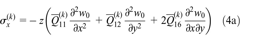
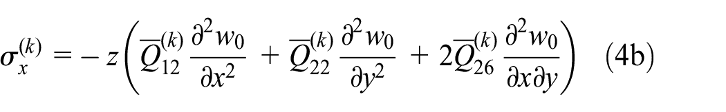
The in-plane stress component is expressed as follows

The damping layer approximates an isotropic material. Its constitutive relation is expressed as follows
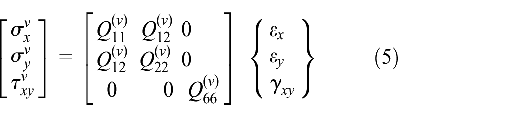

where
By bringing equation (3) into equation (5), then equation (5) can be re-expressed as follows


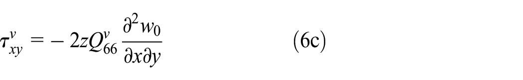
Physical components
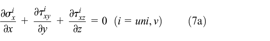

where uni represents generalized orthotropic layer; v represents damping layer.
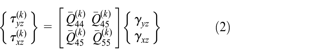
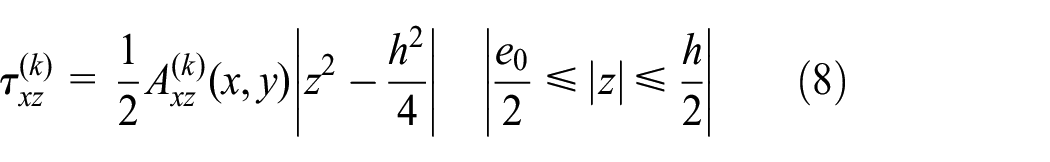
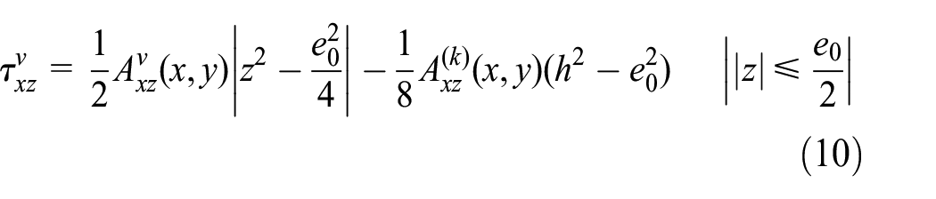
By bringing equations (4) and (6) into equation (7) and using stress continuous conditions and stress boundary conditions, the xz direction shear stress of anisotropic layers and damping layers can be obtained as follows


Similar to the above process, the yz direction shear stress of anisotropic layers and damping layers can be obtained as follows


Calculation of loss factor
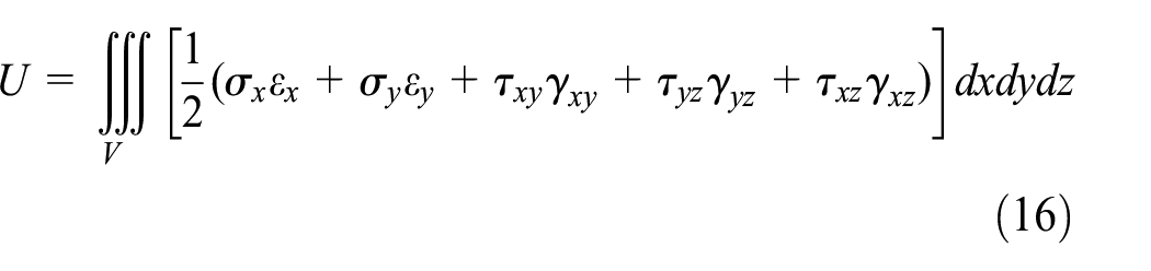
For linear elastomers, the total strain energy is expressed as follows
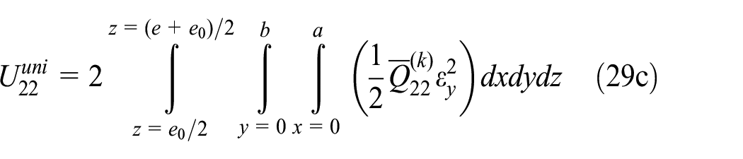
The in-plane strain energy of a generalized orthotropic layer is expressed as follows
Using the Ritz method, the deflection function is expressed by the double Fourier series and the beam modal function is as follows

where


When the boundary condition is clamped on four sides, the coefficients


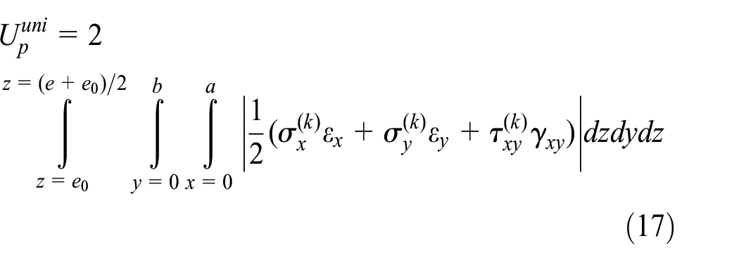
In-plane strain energy of damping layer is shown in the following formula

The strain energy of the composite layer in the xz direction is expressed as follows

The strain energy of the composite layer in the yz direction is expressed as follows

The strain energy of damping material layer in the xz direction is expressed as follows

The strain energy of damping material layer in the yz direction is expressed as follows

where G represents the shear modulus of damping material.
The expression of modal loss factor is expressed as follows
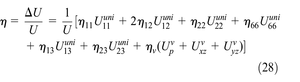


where
Validation of the theory
The loss factor can be represented by the deflection function
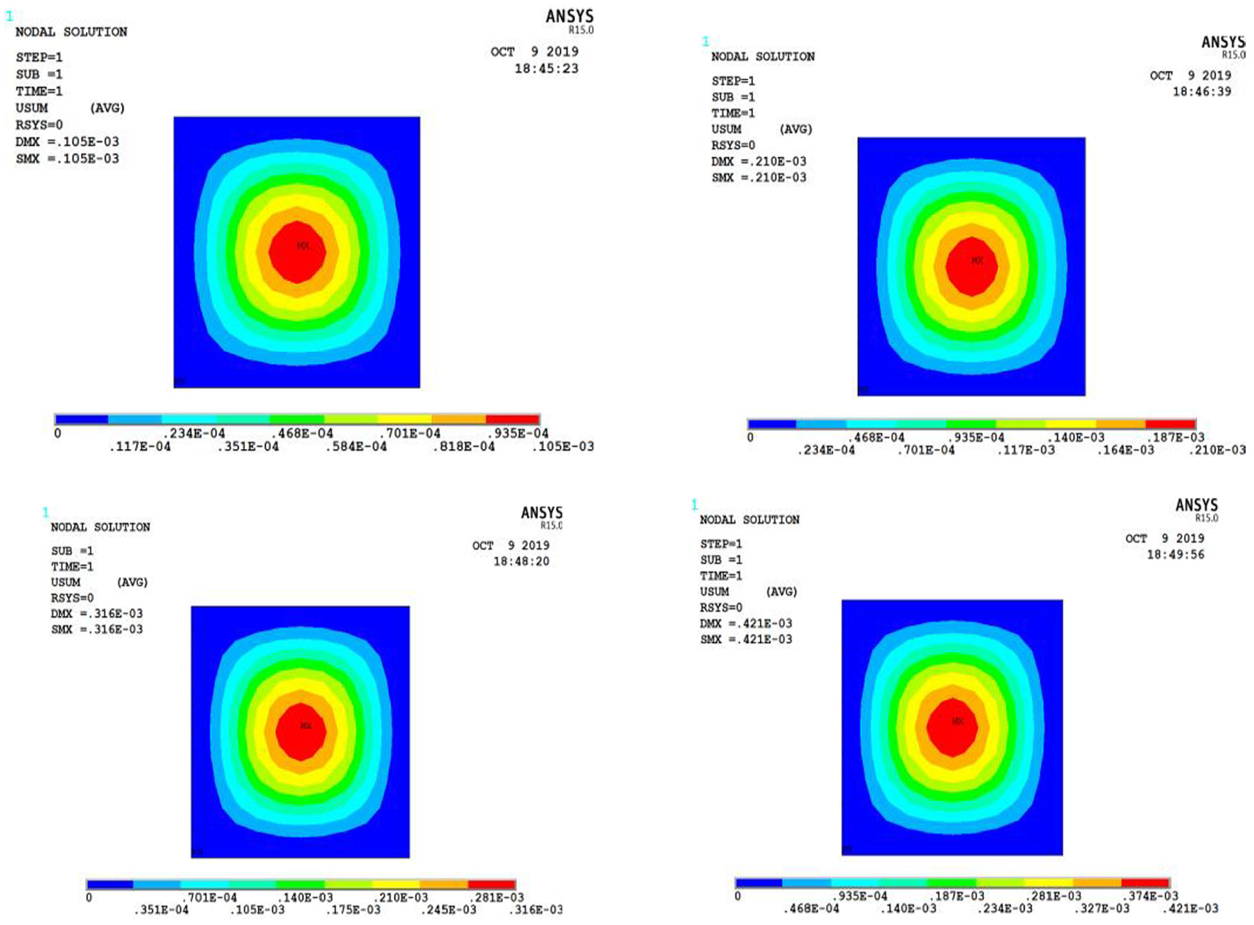
Displacement cloud diagram of the structure under various loads.

Comparison of theoretical and finite element values of deflection.
Deflection value of the structure under the uniform load of 5000 N/m2.

Figure 4 and Table 1 demonstrate that although there are some differences between the theoretical value and the value calculated using ANSYS software, they are basically consistent. The basic assumptions made by this theory and the size of the cells in the finite element lead to the generation of errors. The value calculated using ANSYS software verifies the correctness of the theoretical analysis of the deflection function
Influence of various parameters on the loss factor of thin plates
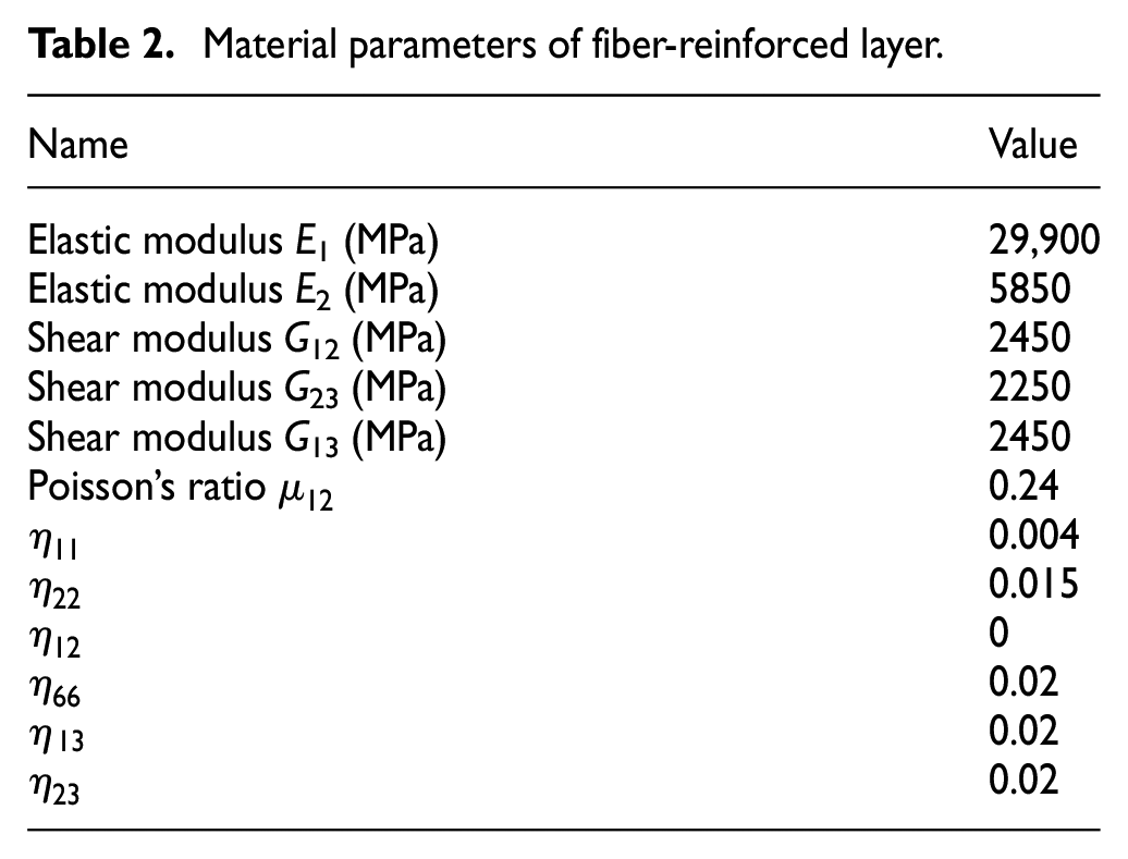
In order to obtain the maximum loss factor of ECCDS, the material parameters in the study by Berthelot and Sefrani 27 were used to study the effects of various parameters on the loss factor of ECCDS. The performance parameters of the E-glass fiber/epoxy resin angle-ply composite material in the structure are shown in Table 2, and the performance parameters of the damping material are shown in Table 3.
Material parameters of fiber-reinforced layer.
Damping material parameters.

The effect of damping layer thickness on loss factor
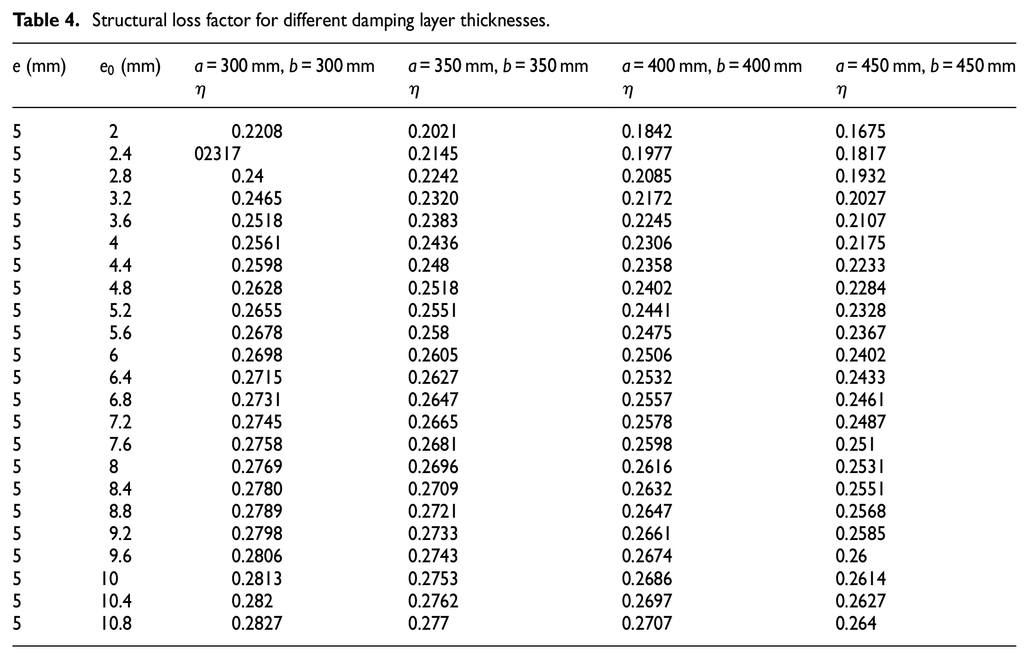
Under the premise of keeping the thickness of the composite layer unchanged, the thickness of the damping material layer is gradually increased, and the total thickness of the thin plate is gradually increased. The structural loss factors of different damping layer thicknesses are solved by the Ritz method. The results are shown in Table 4 and Figure 5.
Structural loss factor for different damping layer thicknesses.

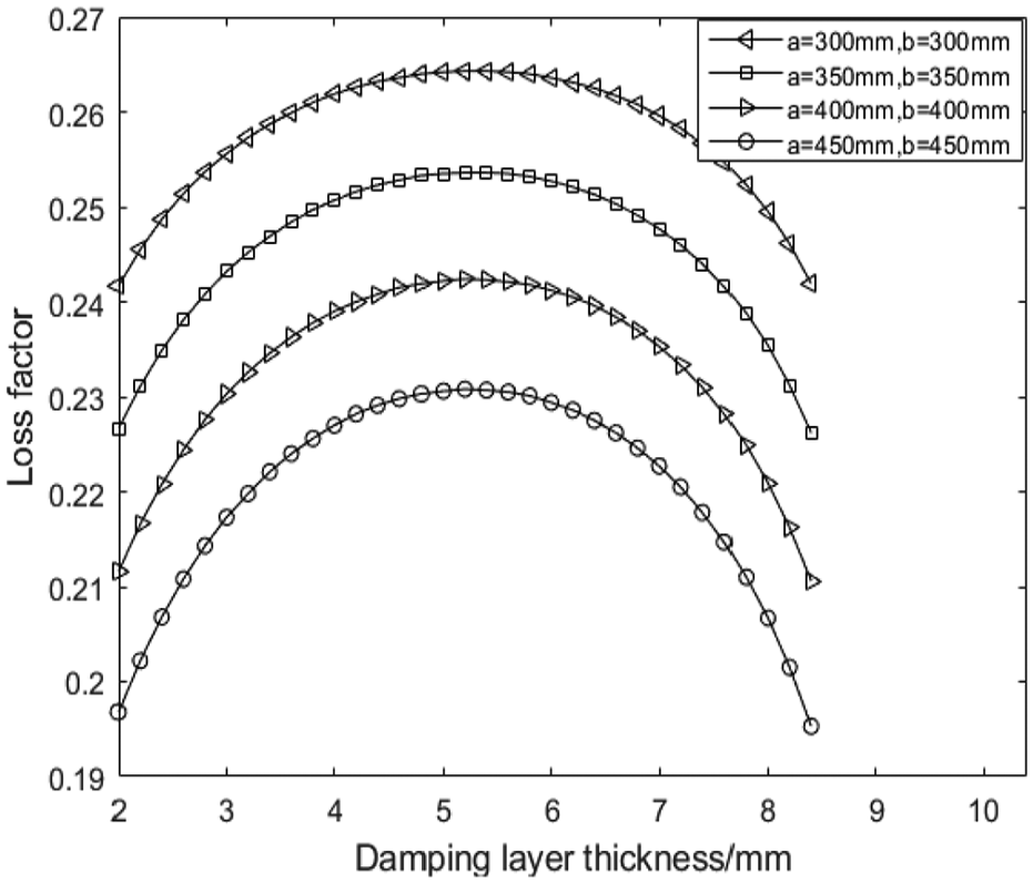
Change law of loss factor with the thickness of damping layer.
Table 4 and Figure 5 show that increasing the thickness of the damping layer can increase the loss factor and smaller square plates have a larger loss factor. The rate decreases constantly from
The effect of the thickness of the composite layer on the loss factor
While maintaining the thickness of the damping layer of the thin plate, the thickness of the composite layer is gradually increased, and the total thickness of the thin plate is gradually increased. The structural loss factors of different composite layer thicknesses are solved by the Ritz method. The results are shown in Table 5 and Figure 6.
Structural loss factor for different composite layer thicknesses.


Change law of loss factor with the thickness of composite layer.
From Figure 6, it can be seen that as the thickness of the composite panel layer increases, the loss factor of the structure increases. Increasing the thickness of the composite panel layer, the upper and lower skin layers strengthen the restraining effect on the damping material layer, and the damping material layer undergoes sufficient shear deformation, and the loss factor increases accordingly. The rate decreases constantly from
The total thickness of the thin plate remains unchanged, and the effect of damping layer thickness on loss factor
Under the premise of keeping the total thickness of the thin plate unchanged, the thickness of the damping material layer is gradually increased, and the thickness of the composite layer is gradually reduced. The loss factor of the thin plates with different damping thicknesses is calculated. The calculation results are shown in Table 6 and Figure 7.
Structural loss factor for different damping layer thicknesses.

Change law of loss factor with the thickness of damping layer.
From Table 6 and Figure 7, when the total thickness of the thin plate is constant and the thickness of the damping layer is increased from 2 to 5.2 mm, the loss factor increases with the thickness of the damping layer; when the damping layer is thick, the loss factor is no longer sensitive to the thickness of the damping layer. When the thickness of the damping layer increased from 5.2 to 8.4 mm, the loss factor of the structure decreases correspondingly. As the thickness of the damping layer increases and the thickness of the composite panel decreases, the upper and lower skin layers weaken the restraining effect on the damping material layer, the shear deformation of the damping material layer becomes insufficient, and the loss factor decreases.
The effect of layer angle on loss factor
In order to study the influence of the layer angle on the loss factor of ECCDS, the loss factor of the thin plate at different layup angles is calculated. The calculation results are shown in Table 7 and Figure 8.
Structural loss factor for different layer angles.


Change law of loss factor with the layer angle.
It can be seen from Table 7 and Figure 8 that the loss factor variation of the structure is related to the layup angle, and the variation of the layup angle has less influence on the loss factor. Generally, as the angle of the layer increases, the loss factor first increases and then decreases. When the layer angle is pi/4, the shear deformation of the damping material layer is more sufficient and the maximum value of the loss factor was obtained. Therefore, setting the laminate layer angle to pi/4 will help to improve its damping performance. In the case where the layup angle is the same, the loss factor of the smaller square plate is larger.
Conclusion
In order to obtain the maximum loss factor of the embedded co-cure damping composite structure, the strain energy of each stress component is deduced using the Ritz method, and the loss factor of embedded co-cured damping composite is calculated. The effects of various parameters on the loss factor of embedded co-cured composite damping structure are studied. Detailed conclusions are listed as follows:
When the damping layer thickness of ECCDS is constant, the loss factor of ECCDS increases with the increase of the composite layer thickness. If the composite layer in ECCDS is thick enough, the loss factor of ECCDS is not very sensitive to the increase in the thickness of composite layer.
When maintaining the composite layer thickness of ECCDS, the loss factor of ECCDS increases with the increase in the damping layer thickness. If the damping layer in ECCDS is thick enough, the loss factor is no longer sensitive to the change of the damping layer thickness.
When the total thickness of ECCDS is constant, the loss factor increases first and then gets down with the increase in the thickness of the damping layer, the distribution is in the form of the convex parabola, and the maximum value of the loss factor can be solved.
The variation in the layer angle has less influence on the loss factor. As the angle of the layer increases, the loss factor first increases and then decreases. When the layer angle is pi/4, the loss factor takes the maximum value.
Footnotes
Handling Editor: James Baldwin
Declaration of conflicting interests
The author(s) declared no potential conflicts of interest with respect to the research, authorship, and/or publication of this article.
Funding
The author(s) disclosed receipt of the following financial support for the research, authorship, and/or publication of this article: The work was financially supported by the National Natural Science Foundation of China (grant number 51375248), the Natural Science Foundation of Shandong Province (grant number ZR201807070249), Study on Formation Mechanism of Solid Copper Solution and Copper–Aluminum Phase in Copper–Aluminum Liquid–Solid Composite Process (grant number 2018WKSD009), the Doctoral Fund Project of Weifang University of Science and Technology (2017BS13), the Talent Special Fund Project of Weifang University of Science and Technology, and Facility Horticulture Laboratory of Universities Program in Shandong (grant number 2018YY049 and 2018YY018).