
Abstract
The damping characteristics of the joint interfaces affect the dynamic behaviors of a whole accurate machine construction notably. An equivalent material damping model between the joint interfaces under the tangential force is established based on contact theory and micro-slip theory. A quantitative analysis of the damping which is characterized by the equivalent loss factor β is presented. Through the numerical simulation, the influences of the joint parameters (such as tangential force, normal force, and friction factor) on damping loss factor are investigated. The numerical simulation result shows that under the condition of micro-slip (T < µP), the equivalent damping loss factor increases with the tangential force growing but decreases as normal force and friction factor increase. Finally, through comparison with traditional joint interface model, the effectiveness of the equivalent damping model has been verified.
Introduction
A complicated mechanical structure, such as machine tool, is generally assembled by many components using various joint interfaces. The dynamic characteristics of these joints influence the static and dynamic characteristics of the mechanical structure significantly due to the low contact stiffness and high contact damping. The damping plays an important role in reducing the structural vibration and improving the structure fatigue characteristics, and Murty and Padmanabhan 1 and Padmanabhan and Murty 2 indicated that more than 90% of the total damping in a structure originates from the joint interface. However, most of the theoretical researches focus on the contact stiffness rather than contact damping since the damping mechanism of the joint interface is not yet clear. Therefore, an estimation of the contact damping of the joint interface is important for improving the dynamic characteristics of the mechanical structures.
The damping of the joint interface is an essential role hindering the relative motion of the object and transforming the mechanical energy into thermal energy. Mindlin 3 deduced the analytic solution of energy dissipation at contact of a flat plate with spheres, and it is implied that the energy dissipation of the joint interface is mainly caused by micro-slip. Dai 4 proposed that for dry friction of the joint interfaces, the energy dissipation suffering normal force is very small, but the tangential force consumes energy and forms the damping effect. Rogers and Boothroyd 5 revealed that the energy dissipation of the joint interface per cycle can be detected under tangential alternate force and proved that the energy dissipation is unrelated to the frequency of the tangential force. Padmanabhan 6 used surface response method and conducted damping dissipation prediction research on a variety of metal joint interfaces suffering tangential forces and gave the first-order orthogonal empirical model of energy loss per cycle.
To describe the properties of the joint interface, an accurate model is necessary. From macro perspectives, Iwan 7 developed a relatively simple model for the hysteretic behavior of the structures. This model is based on the approach which assumed that the system is composed of a series of so-called Jenkin’s elastic–plastic elements. Based on this model, Segalman8,9 built a four-parameter model to reproduce the qualitative and quantitative properties of lap-type joints. The parameters are deduced by matching the experimental values of energy dissipation and loss factor in harmonic loading and the values of the force.
Essentially, the joint interface is the mutual interaction of the asperities distributed over the whole rough surfaces in micro-scale. Greenwood and Williamson 10 took the surface topography parameters into account for the first time and established the model of elastic rough surface contact. In this model, some assumptions are adopted as follows: the rough surface is isotropic, the asperities are spherical, all the asperities have the same radius, the height of the asperities is random, the deformation of the given asperity is not influenced by any other asperity, and there is no bulk deformation. A contact solution for elastic bodies was applied to a series of asperities following a given statistical height. In fact, the rough surfaces are fractal in structure within millimeter scales and nano-scales, and the statistical parameters such as height, slope, and curvature of asperity are scale-dependent. Thus, this model cannot provide unique predictions. Based on the fractal characterization of the rough surface, Majumdar and Bhushan 11 put forward the elastic–plastic fractal model of the rough surface. In their work, the form for the distribution of the island areas is used to approximate the distribution of the contact areas, due to the close fractal resemblance between islands over the sea level and the truncated asperities of the rough surface. They equated a given contact diameter to a wavelength and used the fractal dimension and fractal roughness parameter to provide the deformation of the asperity. Furthermore, the relationship between the real area of contact and the applied normal load is established. Compared with the traditional statistic parameters, the fractal dimensions and characteristic scale are independent in dimension to some extent. However, the assumption they made that the asperity was completely flattened led to a counterintuitive result. They predicted that all contact spots of area less than a critical area are in plastic contact and the percentage of plastic deformed contacts will be greater with the load being lighter. Jackson and Streator 12 reviewed the advantages and drawbacks of Greenwood and Williamson (GW) and Majumdar and Bhushan (MB) models, and they described a non-statistical multi-scale model of the normal contact of the rough surfaces.
Recently, MB fractal theory 11 is used in the modeling of the contact stiffness and contact damping of the joint interface. Based on this theory, Zhang et al. 13 proposed a tangential damping and its dissipation factor model of the joint interface. Tian et al. 14 established a virtual isotropic material equivalent model of the fixed joint interface based on MB model and deduced the analytic solution of the equivalent elastic modulus, Poisson’s ratio, and density of the virtual material. The theoretical results match well with the experimental ones in natural frequency and model shapes. Meanwhile, this virtual model has the advantage of greatly simplifying the modeling process of the joint surface in the finite element analysis. In their research, the stiffness property of the equivalent virtual material is only considered, but the damping property is ignored. However, the damping mainly affected the resonant amplitude, which is also an important indicator for the dynamic property of the mechanical structure. Thus, based on the study of Tian et al., 14 the damping factor of the joint interface will be deduced using the virtual isotropic material equivalent model in the following section.
The outline of this article is as follows. In section “Equivalent material model and material damping,” the traditional spring–damping model is reviewed and the equivalent virtual material model is established. In section “Energy dissipation and damping factor,” the energy dissipation and damping factor of the equivalent material under tangential force are obtained. In section “Analytical simulation and discussion of results,” the analytical simulation and discussion of results are given. In section “The validation of the effectiveness of proposed model,” the validation of the effectiveness of proposed model is discussed.
Equivalent material model and material damping
To accurately reflect the static and dynamic properties of the joint interface, an appropriate model is necessary. At present, the equivalent spring–damping model is usually established when dealing with the stiffness and damping of the fixed joint interface in the finite element analysis, which is indicated in Figure 1. The normal and tangential dynamic characteristics of the joints are tokened by the spring–damping elements. To describe a spring–damping element, three directions of stiffness coefficient kx, ky, and kz and damping coefficient cx, cy, and cz are usually employed. The advantage of the spring–damping models lies that if the number and position of the element are appropriate, the static properties of the joint interface can be reflected and the natural frequency and modal shape can match well with the experimental results. Nowadays, this model is adopted for the finite element analysis of the joints in most studies, but some drawbacks still exist in this model including the following:
The linear dynamic model cannot reflect the nonlinear characteristics of the joint interface.
The spring–damping elements are independent of each other neglecting the coupling influence.
The stiffness and damping values are generally obtained by experimental calibration, and the parameters identified by this model are applicable only for the current joint interfaces.
The finite element analysis is a valid and accurate alternative; nevertheless, the spring–damping element modeling is time consuming.
It is difficult to precisely ascertain the number of spring–damping elements because the number depends on the contact area, the contact form, the number of the bolts, and the arrangement of bolts.
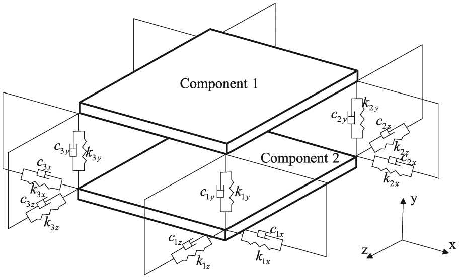
Spring–damping model of three DOFs.
The virtual material equivalent model of the fixed joint interface was established by Tian et al., 14 and the analytic solution of equivalent elastic modulus, Poisson’s ratio, and density of virtual material were also deduced. As shown in Figure 2, this model transforms the mechanical structure including flexible joint interface into two components in rigid contact with the virtual materials. In order to approximate more accurately the real contact, the area of the virtual material should be the same as that of the joint interface. Equivalent spring–damping element is not needed in the finite element analysis and therefore the modeling is accelerated. The stiffness of the joint interface can be described by the elastic modulus and Poisson’s ratio of the virtual material, and the damping of the joint interface is described through the damping factor of the virtual material. Using this model, the damping factor of the virtual material will be deduced in the following section.

Virtual material equivalent model of fixed joint interface.
For general damping material, the damping factor under shear stress and strain can be expressed as

Equation (1) is the physical meaning of the material loss factor, where
Energy dissipation and damping factor
To obtain the energy dissipation of the joint interface, the microscopic mechanism must be made clear first. The contact between the rough surfaces is essentially the contact and interaction between the asperities. In the modeling and mechanical analyses, to simplify the problem, two deformable rough surfaces can be equivalent to a smooth rigid plane and a rough surface with the roughness equivalent to the effective roughness of the two original surfaces.
15
This assumption is along with the one given in GW
10
model and modified MB
16
model. The contact shape of the asperities is usually close to semi-ellipsoid; for convenience, it can be considered as a hemispheroid. Under a normal force which is through the sphere center, the asperity will produce elastic or plastic distortion. As shown in Figure 3, the truncated area is defined as a circle area obtained after the asperity is truncated by the rigid plane,

The micro-contact of an asperity and rigid plane.
Given r radius of the real micro-contact area of an asperity and a smooth rigid plane,
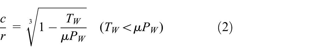
where TW stands for the amplitude of the tangential force on an asperity, PW stands for the amplitude of the normal force on an asperity, and
When an asperity is subjected to a harmonic tangential force TW, the energy input by the system in a cycle is shown in Figure 4. The formula is given by Fouvry et al. 19

where δm is the equivalent tangential relative displacement when the contact of two asperities is modeled as an equivalent sphere in contact with a flat rigid plane, which can be expressed as

where

where G1, v1 and G2, v2 are the shear modulus and Poisson’s ratios of component 1 and component 2, respectively. Similarly, the equivalent elastic modulus of two contact rough surfaces is defined as
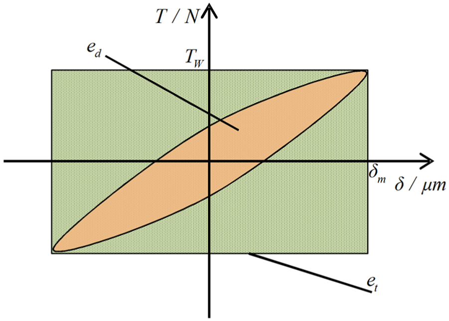
Energy input and dissipation under micro-slip condition of an asperity.
Substituting equation (4) into equation (3) yields
According to the literature, 13 some simplifications and assumptions are given: the topography of a rough surface is isotropic; the interactions among asperities are ignored; the force acting on each asperity is directly proportional to the size of its contact area. Thus, the tangential and normal forces acting on an asperity can be expressed as

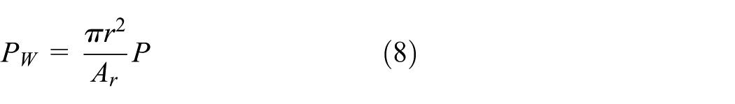
where T is the amplitude of the oscillating tangential force on the whole joint surface, P is the normal force on the whole joint surface, and Ar is the total real area of the joint interface, which is much smaller than the nominal contact area.
Thus, the energy input in a cycle of the joint interface can be obtained as
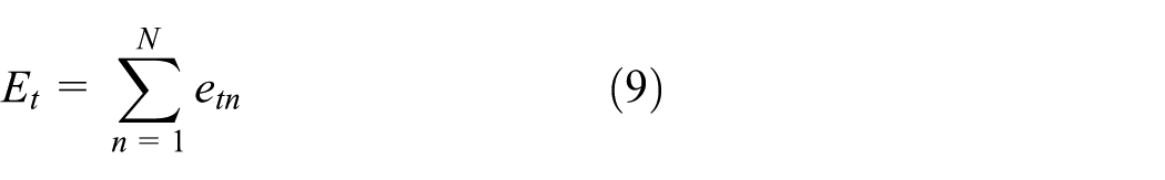
where N is the number of the asperities on the contact interface in elastic interference and etn is the energy input of the nth asperity.
Substituting equations (6)–(8) into equation (9) yields

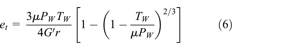
On the other hand, the energy dissipation per cycle for an asperity can be expressed as 19
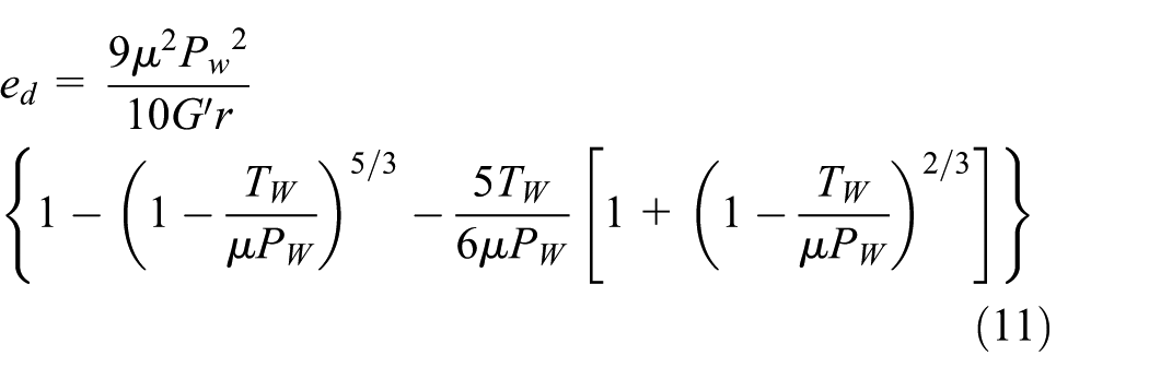
Thus, the tangential energy dissipation per cycle of the joint interface can be expressed as
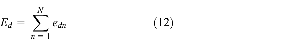
where edn is the energy dissipation of the nth elastic interference asperity.
Substituting equations (7), (8), and (11) into equation (12) yields

Given Ee the maximum elastic energy in a cycle, according to equation (1), the virtual material damping loss factor can be expressed as

where Δ1 and Δ2 are the two nonlinear functions of normal force and tangential force as follows


Analytical simulation and discussion of results
According to equation (14), when oscillating tangential force with amplitude T = 2000 N is given, the relationship between the equivalent damping loss factor and the normal force can be obtained. As shown in Figure 5, the damping loss factor decreases with the increase in normal force. That is because that dynamic tangential harmonic load results in tangential vibration on the surface of the joint interface; as the normal force increases, the real contact area will increase. The vibration amplitude and energy dissipation decrease with the increasing real contact area, and the value of the loss factor decreases as the energy dissipation decreases.

Variation of the damping loss factor with the normal force.
The tangential force T is treated as a variable; the normal force P = 20,000 N is given. The relationship between the equivalent damping loss factor and the tangential force is shown in Figure 6. It can be seen that the damping loss factor increases with the increase in the tangential force because the stick radius will become smaller with increasing tangential force. As the radius of the slip region increases, there will be more energy dissipation in a cycle.

Variation of the damping loss factor with the tangential force.
The relationship between the equivalent damping loss factor and the friction factor is shown in Figure 7. The damping factor decreases with the increment of friction factor, because as the friction factor becomes larger, the tendency of micro-slip will be much less, which results in less energy dissipation.

Variation of the damping loss factor with the friction factor.
The validation of the effectiveness of proposed model
Tian et al. 14 verified the correctness of the equivalent virtual material model by the experiments and the first six-order natural frequencies of the virtual material model have an error within 10% with the experimental result, and the vibration mode keeps consistent. Since the damping of the equivalent virtual material is difficult to be measured by the experiment, and the damping mainly affects the vibration amplitude, hence the response of the structure of the frequency curve can be calculated by harmonic response analysis, indirectly reflecting the damping.
Yoshimura model is a classical spring–damping empirical model to handle the stiffness and damping of the joint interface.20,21 In his research, it is proved that the dynamic data of unit area can be used in the interface with the same surface characteristic even with different shape and contact area as long as the average contact pressure is the same. For a certain structure, the characteristic parameters of unit area can be found out; multiplying by the area of the joint interface, the equivalent stiffness and damping can be obtained. The value of stiffness and damping achieved using this method matches well with the experimental values within a certain range. However, some high-order modal shapes cannot be identified by the experiment sometimes. As a method adopted by many people in the finite element simulation before the producing prototype, it is widely recognized by the engineers. In this article, the validation of the proposed model will be carried out by comparing Yoshimura model with the proposed model.
The model in this article is of the same size as the one in Tian et al., 14 the size of the convex near the joint being 80 × 30 × 45 mm3, and the rest is 230 × 100 × 85 mm3, as shown in Figure 8. The two dumbbell structures are contacted by two inner hexagon M12 bolts and each bolt is applied by the same pre-tightening torque of 30 N m. The material of specimens is HT250, the elastic modulus is 116 GPa, Poisson’s ratio is 0.27, the density is 7340 kg/m3, the yield strength is 240 MPa, and Brinell hardness is 700 MPa. The surface roughness of the contact surface is 3.2 µm. Yoshimura model and virtual materials model were used, respectively, to establish the finite model of the joint interface. With reference to the corresponding chart in the literature 21 and the related parameters in the literature,14,22 for Yoshimura model of the joint interface, the equivalent damping coefficients of x-, y-, and z-directions are 6.48 × 10⁵, 2.14 × 10⁸, and 6.48 × 10⁵ N s/m, respectively. The stiffness can be identified through the values of natural frequency measured by the experiment in Tian et al. 14 the identified equivalent stiffness coefficients of x-, y-, and z-directions are 2.14 × 10⁸, 5.07 × 10⁹, and 1.69 × 10⁹ N/m, respectively. In the virtual model, analytic solutions for the fixed joint interface of the virtual material parameters can be calculated by equations (25), (26), (54), and (58) of Tian et al. 14 These parameters can also be found directly in Tian and colleagues.23,24 The calculated equivalent elastic modulus is 631 MPa, Poisson’s ratio is 0.22, and the density is 7340 kg/m3.

Dumbbell structures connected by bolts.
The finite element models of the dumbbell structures with two methods are shown in Figure 9. In the virtual model, the dumbbell structure and the virtual material layer are meshed by SOLID186 elements. The element thickness of the virtual material layer denotes the normal thickness of the virtual material. According to Tian et al., 14 the thickness for the layer of the elements of the virtual material is chosen as d = 1 mm, representing the real separation of two contact rough surfaces. In the Yoshimura model, the COMBIN14 elements are employed to describe the spring–damping properties. The lower dumbbell structure is constrained with all degrees of freedom at the four corner of the bottom surface. The displacement responses are obtained by the harmonic response analysis.

The finite element models of two methods: (a) virtual material model and (b) Yoshimura model.
If the tangential force is small in a certain range, the displacement responses of the virtual model match well with the Yoshimura model, and the calculation error changes with the increase in the tangential force. When the amplitude of the tangential force is 1 kN, the damping loss factor obtained by equation (14) is 0.005, and the result of the harmonic response analysis is shown in Figure 10. It can be seen that the displacement response of the x- and y-directions between the two models matches well in the low-order frequencies. The displacement response of the z-direction is very tiny, the magnitude of which is two orders lower than that of the x- and y-directions, so the calculation error of two models is large.
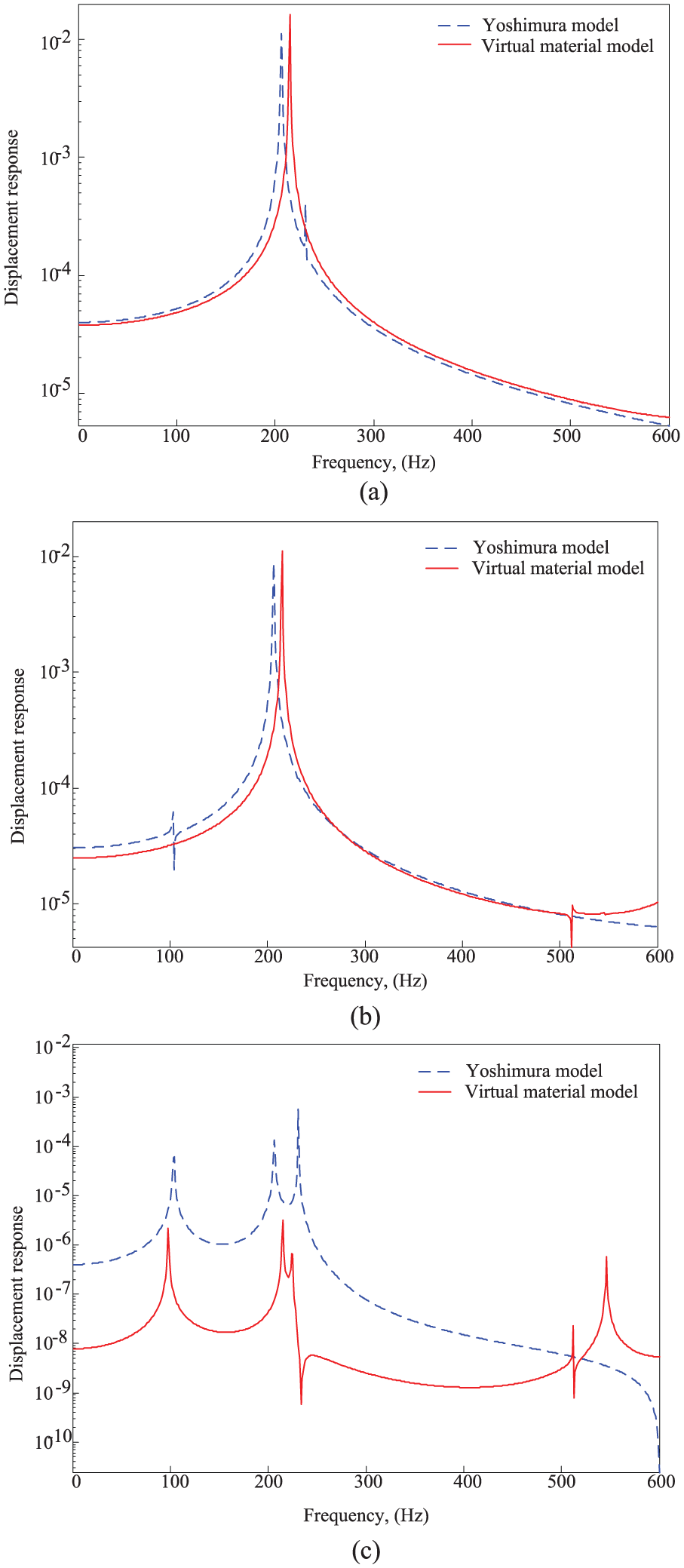
The displacement response curves of two models: (a) the x-direction, (b) the y-direction, and (c) the z-direction.
Conclusion
The model of the equivalent virtual materials of the joint interface is established; the analytic solution of the energy dissipation, the energy input, and the equivalent damping loss factor under tangential force are deduced.
According to the numerical simulation, the equivalent damping loss factor increases with the increase in the tangential force but decreases with the increase in the normal force and friction factor. It provided a theoretical reference frame for the reasonable selection of the value of the damping of the joint interface.
If the tangential force is small in a certain range, the model in this article matches well with the Yoshimura model, and the calculation error changes with the increase in the tangential force. The proposed model can provide a new method for the finite element dynamic analysis when the damping gets involved, and it can speed up the modeling of the finite element analysis.
Footnotes
Academic Editor: Noel Brunetiere
Declaration of conflicting interests
The author(s) declared no potential conflicts of interest with respect to the research, authorship, and/or publication of this article.
Funding
The author(s) disclosed receipt of the following financial support for the research, authorship, and/or publication of this article: This research project was supported by the National Key Science and Technology Special Projects (Grant No. 2013ZX04005-013, 2014ZX04014-011 and 2015ZX04005001).