
Abstract
Aimed at solving the problems of tool wear and poor surface quality in milling a Ti alloy with a ball-end milling cutter, a method of applying a microtexture to a tool rake face to reduce tool wear is proposed in this article. By comparing the wear morphology of microtextured tools with that of nontextured tools after milling with the same stroke, the antifriction and antiwear mechanism of the micropit texture and the failure mode of the ball-end milling cutter are analyzed. The results of a simulation and orthogonal experiments reveal that with the increase of the micropit parameters, the wear value of the rake and rear faces first decreases and then increases. The effects of the micropit parameters on the wear value of the ball-end milling cutter decrease in the following order: distance from edge > diameter > spacing > depth. Finally, by using a multi-objective optimization method, the optimal solution set of the texture parameters of micropits is obtained by evaluating the wear values of the rake and rear faces of the ball-end milling cutters: 46 μm < diameter < 50 μm, 23 μm < depth < 26 μm, 109 μm < spacing < 112 μm, and 85 μm < distance from edge < 89 μm.
Introduction
After summarizing the research status of titanium alloy in recent years, Cai et al. 1 determined that titanium alloy possesses excellent properties, including high specific strength, low density, corrosion resistance, and so on. These alloys have been used in multiple fields, such as aviation, the military, nautical, and petrochemical. However, Ti alloys are typically difficult to machine. In the process of cutting Ti alloys, significant tool wear occurs and tool durability is low, greatly limiting improvements in cutting efficiency of Ti alloys.
Multiple scholars have determined that the preparation of reasonable microtextures on tool surfaces can improve tool-wear resistance, reduce friction, and provide anti-adhesion properties. Xing et al. 2 used a YAG (yttrium-aluminum-garnet) laser to fabricate three types of laser surface textures on the rake surfaces of cemented carbide tools. An orthogonal test of a 6061 Al alloy tube was performed using deformation and a conventional tool. The results indicated that a groove texture can improve the cutting performance of cutting tools for an Al alloy at a low speed. Yang et al. 3 used the ABAQUS platform to establish a simulation model of a microdeformed cemented carbide surface and analyzed the virtual stress distribution to identify the optimal microtexture parameters.
Many friction tests have been performed; several different microstructures have been compared, with the results indicating that microstructures can absorb stress and change the distribution of the surface stress. A spherical-end milling cutter with optimized parameters possesses better wear resistance than a nontextured cutter. Sugihara and Enomoto 4 and other scholars proposed a nano/microtexture surface cutting tool based on femtosecond laser technology. A series of experiments involving cutting an Al alloy were performed. The results demonstrated that the cutting performance of the tool could be effectively improved after the preparation of a meter/microtexture on the surface of the tool. The anti-adhesion effect of the nano/microstructure was also analyzed.
Kawasegi et al. 5 and other scholars developed tools with nano/microstructures to improve the friction behavior. The height and depth of the surface texture varied from hundreds of nanometers to tens of micrometers. The influence of the structure shape on the cutting performance of an Al alloy was studied. It was determined that the cutting force of microscale and mesoscopic cutters on the surface was reduced and strongly depended on the direction of the texture. When the texture was perpendicular rather than parallel to the flow direction of the wafer, the cutting force could be reduced.
Chang et al. 6 and other scholars studied the wear characteristics of cemented-carbide-end milling cutters in microprocessing. Three types of cutting tools with different structure modes were fabricated: microgrooves at horizontal (0°), vertical (90°), and inclined (45°) angles. Three groove-milling experiments were performed to examine the effects of these microstructures on the tool-wear performance. After each groove-milling test, the milling cutter was measured using a scanning electron microscope. The results indicated that the tool had the best wear resistance when the microstructures were cut in the vertical direction.
Tool-wear analysis is essential in high-speed machining, particularly in the process of intermittent cutting and milling. Moreover, analysis of the tool-wear mechanism is useful for improving the tool material performance and cutting performance. Y Li et al. 7 and other scholars performed experiments involving the high-speed dry cutting of a Ti-6Al-4V alloy with cemented carbide tools. The wear mechanism of the cemented carbide tools was analyzed. The results demonstrated that in the process of turning the alloy, the primary wear types of the tools were diffusion, bond, and oxidative wear. A Li et al. 8 used scanning electron microscopy (SEM) to characterize the cross-section of the cutting edge of the wear tool and used energy-dispersive X-ray spectroscopy (EDS) to investigate the element distribution on the surface of the wear tool. The wear mechanism of a coated carbide tool in high-speed cutting of Ti-6Al-4V was studied. The results indicated that the flank wear and spalling were the primary failure modes of the tool.
Wang e al. 9 introduced a new tool material for the high-speed milling of a Ti alloy; it was a new type of boron nitride (BCBN). The performance and wear mechanism of the tool in milling the alloy groove were studied. This tool had a longer service life than common tools and was effective for high-speed cutting. An analysis based on SEM and EDS demonstrated that the primary wear mechanism of the BCBN tool used in Ti-6Al-4V high-speed milling involved the adhesion, wear, and diffusion dissolution of the workpiece. Nouari and Makich 10 analyzed the influence of microstructure on the tool-wear performance, the stability of the cutting process, and examined the cutting process of a Ti alloy using a tool. The changes in the friction, the temperature increase, and the tool-wear data under different cutting conditions were studied. The results demonstrated that adhesion and diffusion are the primary wear types of cutting tools in the processing of conventional Ti-6Al-4V alloys.
Thus, in the process of cutting Ti alloy, a microtexture on the surface of the tool can improve the cutting performance. However, there is a lack of in-depth studies on the influence of the microtexture parameters on the tool-wear value and the optimization of the microtexture parameters. Therefore, in view of the milling process of a titanium alloy with a ball-end milling cutter, a micropit texture was placed on the rake face of the cutter in this study. The mechanism of friction reduction and the wear resistance of the micropit texture were analyzed through comparative experiments. Orthogonal experiments were designed for simulation and experimental analysis, and the effects of the micropit texture parameters on the wear of the ball-end milling cutter were determined. Finally, a multi-objective optimization method was used to obtain the optimal solution set of texture parameters of micropits by evaluating the wear values of the rake face and rear face of ball-end milling cutters. The reliability of the optimal solution was confirmed via a validation test.
Analysis of wear mechanism of microtexture tools
Comparative experimental study on cutting process of microtexture tool and nontextured tool
To study the wear mechanism of microtextured cutting tools, a set of comparative experiments between microtextured cutting tools and nontextured cutting tools for milling Ti alloys was designed. A microtexture was fabricated on the rake face of a ball-end milling cutter via laser processing. The variation in the tool wear with an increase in the cutting stroke was analyzed. Simultaneously, the wear mechanism of microtextured cutting tools was analyzed via optical microscopy and SEM.
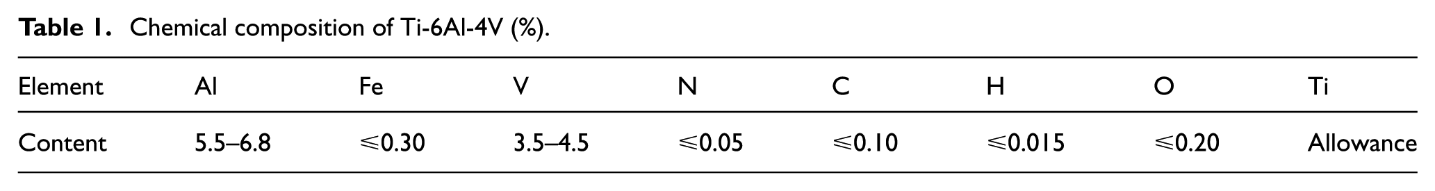
A micropit texture was used in the experiment. The parameters of the micropits were as follows: diameter, 30 μm; depth, 70 μm; spacing, 150 μm; and distance from edge, 120 μm. A suitable micropit texture was prepared by using reasonable laser parameters. The shape, arrangement, and size of the micropit texture were measured using a Keynes VHX-1000 ultra-depth-of-field microscope, as shown in Figure 1.
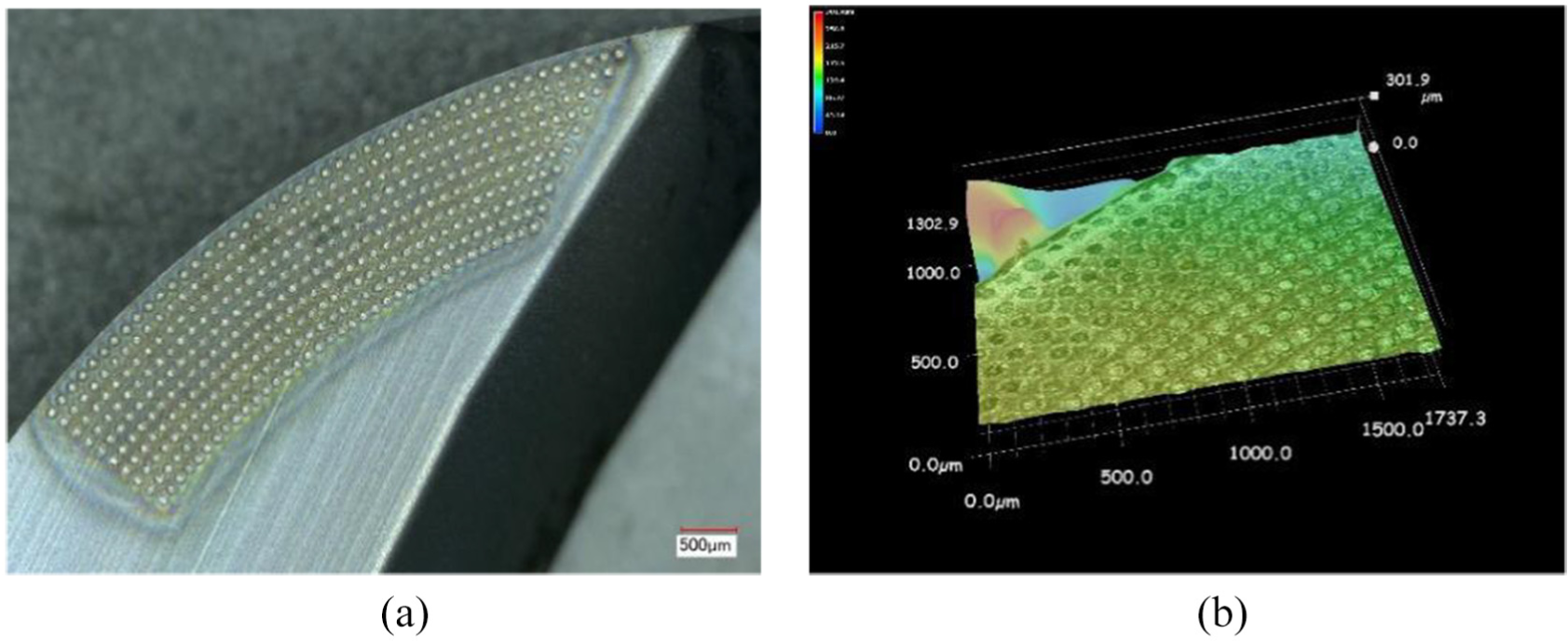
Microtexture tool observations: (a) microtexture arrangement rule and (b) microtexture size and micromorphology.
Ti-6Al-4V was selected as the material of the Ti alloy workpiece. The dimensions of the workpiece were 120 × 80 × 60 mm3, as shown in Figure 2. The chemical composition and physical properties of the workpiece are presented in Tables 1 and 2, respectively.

Dimensions of the workpiece: (a) side view and (b) top view.
Chemical composition of Ti-6Al-4V (%).
Physical and mechanical properties of Ti-6Al-4V.
The type of milling cutter was BNM-200, the diameter of the milling cutter was 20 mm, the rake angle of the cutter was 0°, the rear angle was 11°, the thickness of the blade was 5 mm, and the material of the cutter was cemented carbide, as shown in Figure 3.
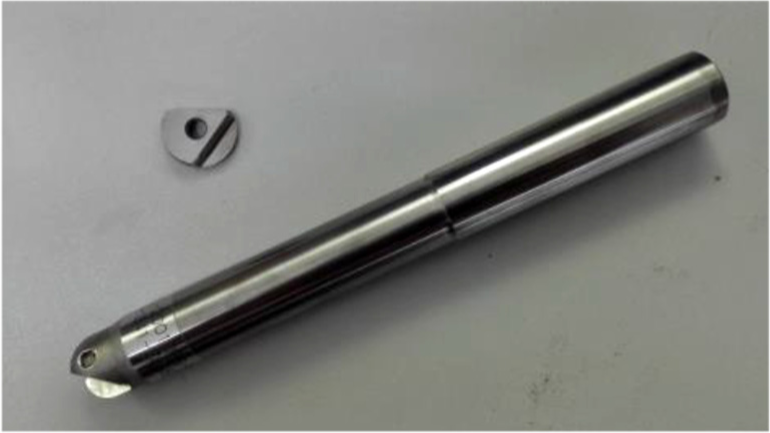
Milling bar and inserts used in the experiments.
Yongwang Dong 11 studied the influence of different feeding modes on the cutting performance of ball-end milling cutters when milling inclined surfaces, and found that in order to avoid the tool tip from participating in cutting, the inclined angle of inclined surfaces has a corresponding relationship with cutting parameters and the cylindrical radius of milling cutters. According to the profile uphill milling method and milling parameters in this article, the inclination angle of the workpiece for milling was set as 15°, and the forward-milling method was employed. The milling parameters are presented in Table 3. A VDL-1000E CNC milling machine and a Kistler 9257B dynamometer were used in the experiment. A field diagram of the experiment is shown in Figure 4.
Cutting parameters.


Experimental setup: (a) force-acquisition equipment and machine tools and (b) sinusoidal tongs and workpieces.
Ten cutters were used in the comparative experiment, of which nine were microtexture cutters with the same texture parameters as the micropits, and one was a nontextured cutter. The milling width was ae = 0.5 mm, the slot width of the selected Ti alloy workpiece was 7 mm, and the total width was 80 mm. The calculation results showed that one slot per milling could be obtained, and the milling stroke was 1120 mm. The milling strokes of the first, second, and third micropit texture cutters were designed as L1 = 3360 mm, L2 = 2 L1, and L3 = 3 L1, respectively. Accordingly, the milling stroke of the ninth cutter was L9 = 9L1 = 30,240 mm. The milling stroke of the nontextured cutter was L10 = L9.
After the milling experiment, the tool used in the experiment was observed using a super-depth-of-field microscope and a scanning electron microscope, and the change rule of the tool wear with an increase in the milling stroke was analyzed. The KB value of the tool rake wear and the VBmax value of the tool flank wear were measured. The tool-wear values at the two cutting edges of the ball-end milling cutter were represented as a and b. The results are presented in Table 4. According to the data in the table, a tool-wear histogram was drawn, as shown in Figure 5.
Tool-wear values.


(a) cutting tool rake face of the wear value and (b) cutting tool flank wear value.
As indicated by Table 4 and Figure 5, the wear of the micropit texture cutter was significantly lower than that of the nontextured cutter, for both the KB value and the VBmax value. Therefore, inserting a micropit texture on the rake face of a cutter can effectively reduce the tool wear.
Analysis of antifriction and antiwear mechanism of microtexture
The effects of the micropit textures on reducing the tool wear were analyzed. The mechanism of friction reduction and the wear resistance of the micropit texture were analyzed by comparing the energy spectra of the micropit texture cutter after cutting.
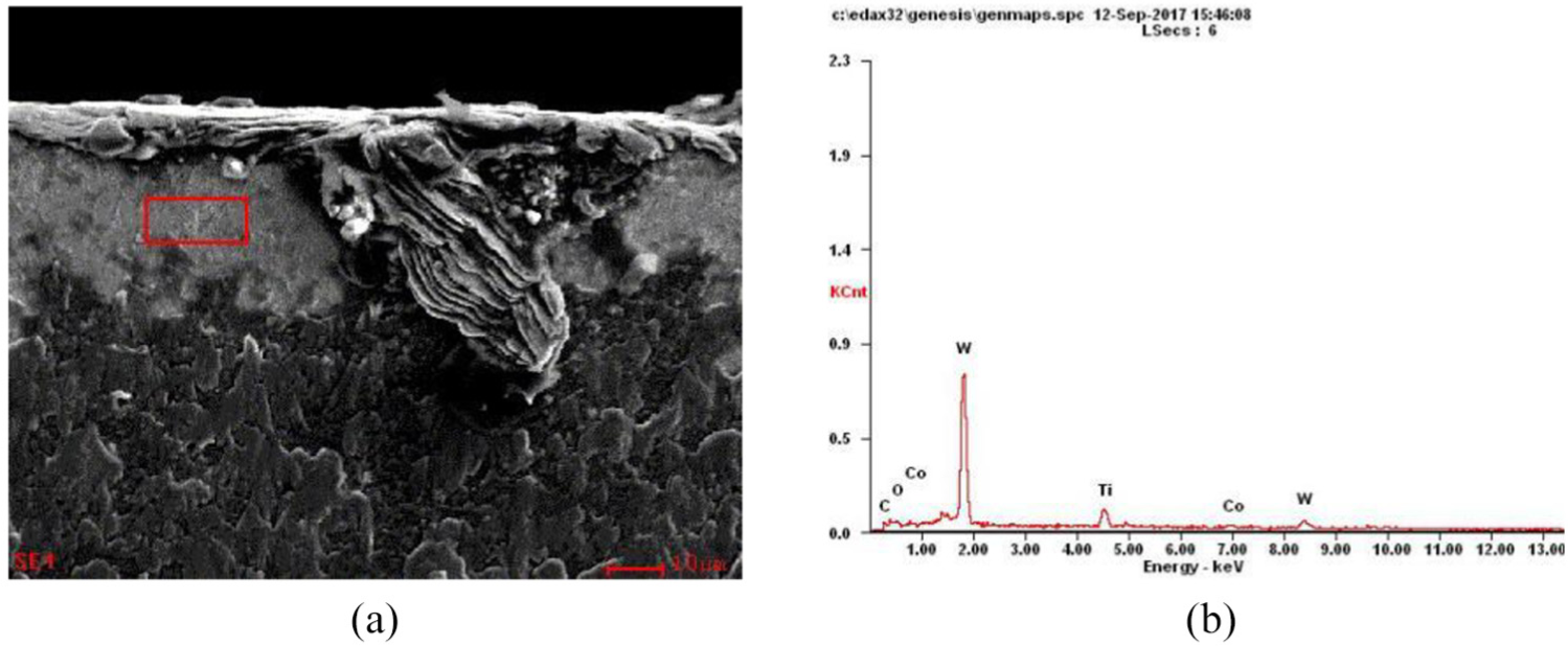
First, the EDS spectra of a group of micropits in and around the cutter–chip peak contact area were measured. As shown in Figures 6 and 7, the analysis revealed that the composition of the micropits did not change (mainly WC and Co), whereas around the micropits, there was some Ti, in addition to WC and Co. This proves that element diffusion occurred between the two types of dielectric materials in the cutting process.

Analysis of the micropit in peak contact area: (a) SEM image and (b) energy-spectrum analysis results.

Analysis of the micropit in peak contact area: (a) SEM image and (b) energy-spectrum analysis results.
The EDS spectra of a group of micropits in the cutter–chip close contact area and around the micropits were measured. As shown in Figures 8 and 9, the bonding phenomenon at the edge of the micropit was more obvious than that in the peak contact area. The content of Ti around the micropit was similar to that in the peak contact area, and O and Ti were observed inside the micropit. This indicates that the bond wear of the tightly contacted area was more severe than that around the micropit and was accompanied by oxidative wear. The resulting oxides and carbides were collected by the micropits after the chips were separated from the Ti alloy matrix, reducing the friction between the rake face and the chips. Therefore, micropits can reduce the wear of the rake face.

Analysis of the micropit in close contact area: (a) SEM image and (b) energy-spectrum analysis results.

Analysis of the micropit around close contact area: (a) SEM image and (b) energy-spectrum analysis results.
Finally, SEM images of a group of micropit-textured tool rear faces were obtained. As shown in Figure 10, the rear face contained O and Ti, and the bonding phenomenon was obvious. Therefore, the wear of the rear face mainly comprised bonding wear, oxidative wear, and diffusion wear.
Analysis of the microtexture of cutter flank wear: (a) SEM image and (b) energy-spectrum analysis results.
Wear simulation of microtextured ball-end milling cutter in milling Ti alloy
Establishment of simulation model
To investigate the effects of the micropit texture parameters on the tool wear, four micropit parameters (micropit diameter, micropit depth, micropit spacing, and micropit distance from the edge) were selected as experimental factors, and orthogonal experiments with the four factors and five levels were designed. A simulation analysis of the orthogonal experiment was performed by using the DEFORM software, and the effects of the different texture parameters on the tool wear were examined according to the simulation results.
Table 5 presents the factor levels for the simulated texture parameters. D represents the diameter of the micropits, H represents the depth of the micropits, L1 represents the spacing between the micropits, and L2 represents the distance from the edge.
Simulation texture parameter factor levels.

The material of the microtextured ball-end milling cutter was cemented carbide, and the workpiece material was Ti-6Al-4V. To ensure the accuracy of the finite-element simulation results, the Johnson–Cook constitutive equation was adopted. The material parameters of the Johnson–Cook model of Ti-6Al-4V are presented in Table 6. A, B, n, m, and C are the structural constants of the model. E is the Young’s modulus, μ is the Poisson’s ratio, and
Ti alloy Johnson–Cook material model parameters.

UG software was used to construct a three-dimensional model, and the model was imported into DEFORM for pretreatment and meshing. The quality of the meshing directly affected the accuracy of the simulation results. Therefore, mesh refinement of the machining area was performed. The total number of meshes was set as 50,000, and the refinement ratio was 0.068, which ensured the accuracy of the simulation and the convergence of the simulation process. The three-dimensional model and mesh generation are shown in Figure 11.

Three-dimensional model and mesh division of the microtexture tool and workpiece.
Analysis of simulation results
The maximum wear value of the tool after the simulation is presented in Table 7. After data processing, an index-factor diagram of the microtexture parameters was drawn, as shown in Figure 12. Tool-wear nephograms are shown in Figure 13. The range analysis of the data in Table 7 indicates that the main factors affecting the tool wear were the diameter of micropits (D) and the distance from the edge (L2). The effects of the four factors on the tool wear decreased in the following order: distance from the edge > diameter of micropits > spacing between micropits > depth of micropits.
Tool-wear simulation results for an orthogonal table.


Indicators: factor diagram.
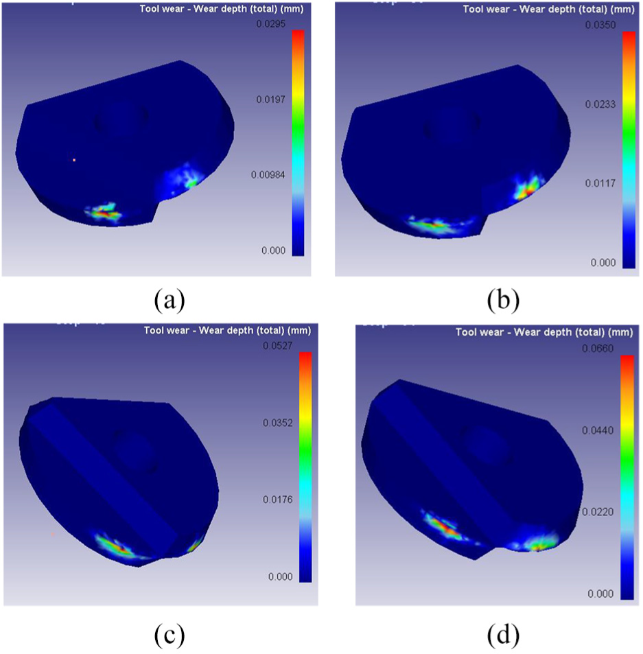
Microtexture tool-wear cloud pictures: (a) step 50, (b) step 100, (c) step 150, and (d) step 200.
According to the total tool-wear nephogram in Figure 13, the wear of the rear face of the ball-end milling cutter was greater than that of the rake face at different cutting stages. Because the milling method was single-tooth cutting, most of the cutting work was performed by one cutter tooth, and the other cutter tooth was less involved in the cutting. Therefore, in the wear nephogram, the wear amount of the two cutter teeth always exhibits a state of >1. As shown in Figure 12, with an increase in the microtexture parameters, the influence of the parameters on the tool wear first decreased and then increased.
Experimental study on wear of microtextured ball-end milling cutter milling Ti alloy
Tool design and test design
According to the simulation results, a wear test was performed with smaller pit-parameter ranges: 40 μm < D < 70 μm, 20 μm < H < 35 μm, 110 μm < L1 < 140 μm, and 90 μm < L2 < 120 μm. Considering the cost and efficiency, a four-factor and four-level orthogonal experiment was designed to explore the effects of the different texture parameters on the wear of the ball-end milling cutter.
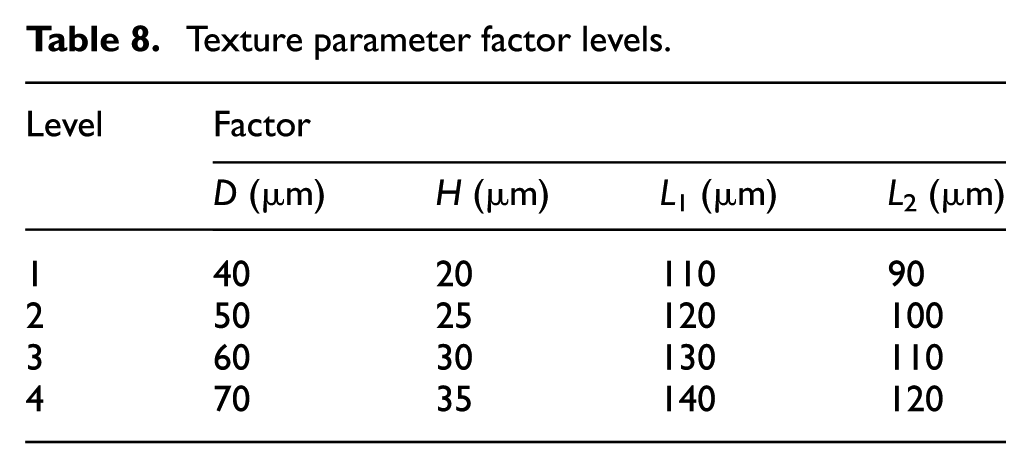
The preparation of a micropit texture on the rake face of the ball-end milling cutter was completed using a fiber laser, and the preparation process was the same as that previously described. The workpiece materials and cutting parameters used in the milling test were the same as those used in the comparative test. The milling stroke of each tool was 30,240 mm. After the milling, the wear of the tool was observed using an ultra-depth-of-field microscope to measure the wear values of different tools. The factor levels of the micropit texture parameters are presented in Table 8.
Texture parameter factor levels.
Analysis of wear results for microtextured tools
After the experiment, the rake-face wear value KB and rear-face wear value VBmax of the cutter teeth with a large wear amount of the ball-end milling cutter were recorded in an orthogonal table, as shown in Table 9.
Microtexture cutter milling test data.

As indicated by Table 8, the wear value of the rear face of the ball-end milling cutter with a micropit texture was always greater than that of the rake face, which is consistent with the simulation results. Data processing was performed on the wear values of the rake face and rear face, and a line chart indicating the changes in the wear amount with respect to the micropit texture parameters was drawn, as shown in Figure 14.

Rake-face and rear-face wear curves for the microtexture tool (a) microtexture effect of tool rake face and (b) microtexture effect of tool flank wear.
As shown in Figure 14, the change trends of the wear values of the rake face and rear face with respect to the microtexture parameters were essentially identical. With an increase in the microtexture parameters, the wear values of the rake face and rear face both exhibited a trend of decreasing first and then increasing. Because the placement position of the microtexture was the rake face in this study, the influence mechanism of the microtexture parameters on the rake-face wear value of the ball-end milling cutter was analyzed.
With an increase in D, the ability of the micropit texture to capture chips was enhanced, the friction between the chips and the rake face was reduced, and the wear value of the rake face was reduced. For D > 50 μm, with an increase in D, the structural strength of the cutter–chip contact area gradually decreased, and the wear of the rake face increased. With an increase in H, the total number of chips that could be collected by the pit increased, the friction between the chips and the rake face decreased, and the rake-face wear value decreased. For h > 25 μm, with an increase in h, the slag generated by laser processing increased at the edge of the pit, the surface roughness of the rake face decreased, the friction between the rake face and the workpiece increased, and the wear value of the rake face increased.
A low L1 led to a lower tool structural strength; thus, with an increase in L1, the tool structural strength increased, and the wear value of the rake face decreased. For L1 > 130 μm, with an increase in L1, the micropit texture became increasingly sparse, the wear-reduction effect of the microtexture decreased, and the rake-face wear value increased. After the microtexture was placed, the structural strength of the cutting edge decreased when L2 was too small. Therefore, with an increase in L2, the structural strength of the cutting edge increased, and the wear of the rake face decreased. For L2 > 110 μm, with an increase in L2, the number of micropits in the cutter–chip tight contact area decreased gradually, the friction reduction and antiwear effects of the micropits decreased, and the wear value of the rake face increased. Analysis of the experimental data revealed that the effects of the four factors on the wear decreased in the following order: L2 > d > L1 > h. This is consistent with the simulation results.
Multi-objective optimization of microtexture tool wear
Wear prediction model for microtextured cutters
Multi-objective optimization is a process of establishing prediction models for multiple objectives and combining multiple prediction models to obtain the optimal solution of the objective equation for the evaluation indices. Through multi-objective optimization, an optimal solution set can be obtained for multiple evaluation indices, so that the solutions in the optimal solution set satisfy each evaluation index.
According to the foregoing tool-wear data, a microtexture tool-wear model with micropit parameters as variables was established, as follows


where x1, x2, x3, x4, y1, y2, y3, and y4 are unknown coefficients related to the pit parameters, and α and β are model correction coefficients related to the wear of the rake and rear faces of the microtexture tool, respectively.
Logarithms were obtained for both sides of equations (1) and (2)

Setup:


The tool-wear data in Table 9 were substituted into equations (5) and (6), and a multiple linear regression analysis was performed to obtain a tool-wear prediction model for a microtexture ball-end milling cutter processing a Ti alloy, as follows


To confirm the accuracy of the microtexture tool model, relevant tests were performed on equations (7) and (8). Tables 10 and 11 present variance analysis results for the wear of the rake and rear faces of the micropit texture tools.
Analysis of variance results for KB.

MS: mean square.
Analysis of variance results for VBmax.

MS: mean square.
According to the significance values in Tables 10 and 11, 0.0314 < F(4, 11) = 3.72, 0.008913256 < F(4, 11) = 3.72. Therefore, the regression model of the microtexture tool has high reliability.
Multi-objective optimization results and verification of microtexture parameters
The decision variables for designing the multi-objective function were the pit diameter d, pit depth h, distance from the edge l1, and pit spacing l2. If x1 = d, x2 = h, x3 = l1, and x4 = l2, the decision variables can be expressed as

The microtexture tool-wear model obtained in section “Wear prediction model for microtextured cutters” was used as the objective function of the microtexture tool optimization, assuming that f1(x) = KB and f2(x) = VBmax. The obtained objective functions are expressed as follows


The microtexture tool parameter decision variables X = [x1, x2, x3, x4] T and tool-wear target spaces f1(x) = KB and f2(x) = VBmax were imported into MATLAB for a genetic analysis

In the genetic analysis, the size of the initial population was designed to be 2000. Relevant variables and functional relationships were setup, and an operation analysis was performed to continuously evolve the population. After several generations of evolution, the Pareto diagram shown in Figure 15 was obtained.

The optimal solution set obtained by considering f1(x) and f2(x) comprehensively.
In Figure 15, the solutions in region A comprise the desired solution set of each function combination, as shown in Table 12.
Information regarding the decomposition of region A.
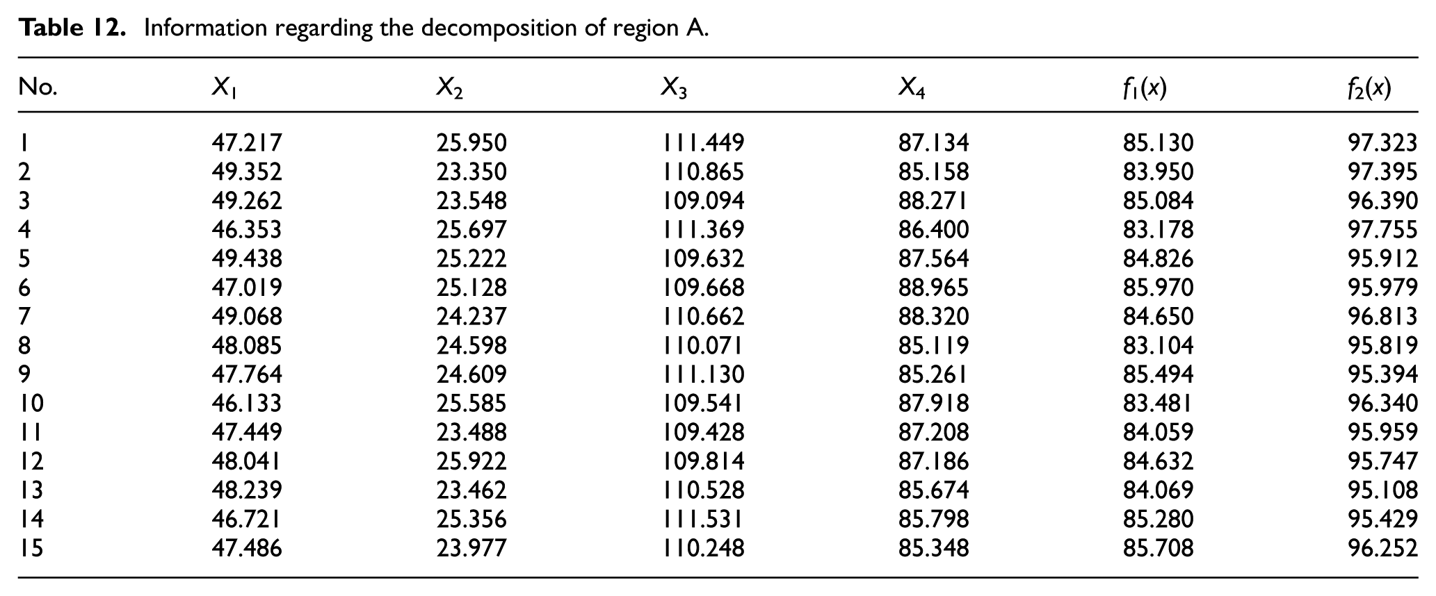
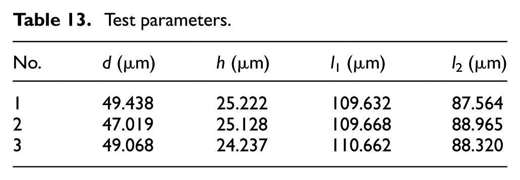
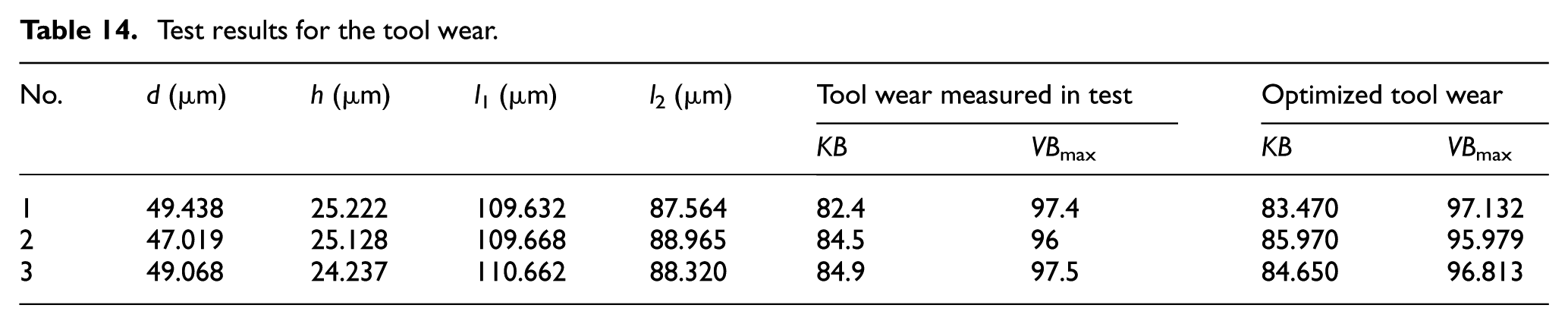
In the obtained optimal solution set A, any three texture parameters were selected and placed in the rake face of the ball-end milling cutter, as shown in Table 13. A milling test was performed using the tool with the optimized microtexture parameters. The test conditions, such as the milling parameters, workpiece size, and workpiece material, were the same as those used in the previous orthogonal test. The wear conditions of three different microtexture tools after milling at 30,240 mm were compared.
Test parameters.
After milling at 30,240 mm, the tool wear was observed using an ultra-depth-of-field microscope and recorded, as shown in Table 14. Calculations indicated that the deviation between the actual wear value of the microtexture tool and the optimized predicted value was less than 2%. Thus, the optimized microtexture parameters had high reliability.
Test results for the tool wear.
Conclusion
The failure mode of a ball-end milling cutter and effect of the microtexture on tool wear were analyzed via a comparative test involving cutting a Ti alloy with a ball-end milling cutter. The effects of the microtexture parameters on the wear of the ball-end milling cutter were determined through a simulation analysis. The accuracy of the simulation results were verified via orthogonal experiments, and the influence mechanism of the microtexture parameters on the rake-face wear of the ball-end milling cutter was analyzed. Multi-objective optimization was performed, where the wear values of the rake and rear faces of the ball-end milling cutters were used as evaluation criteria, and the optimal solution interval was obtained. The main conclusions of this study are as follows:
A comparative experiment involving milling a Ti alloy with a microtexture cutter and a nontextured cutter was performed. EDS energy-spectrum analysis of the microtexture cutter was performed after the milling. The friction reduction and wear-resistance mechanism of the microtexture cutter and the wear mechanism of the ball-end milling cutter were discussed according to an analysis of the tool surface morphology and energy spectrum after wear.
An orthogonal experiment involving milling a Ti alloy using a microtexture ball-end milling cutter was designed with four factors and five levels, and the experimental process was simulated and analyzed. According to the simulation results, the influence rules of the four factors on the tool wear were essentially identical. With an increase in the microtexture parameters, the tool-wear values exhibited a trend of decreasing first and then increasing. The effects of the factors on the wear value decreased in the following order: pit diameter > distance from edge > pit depth > pit spacing.
According to the simulation results, the selection range of the microtexture parameters was optimized, and the orthogonal experiment was redesigned. An analysis of the experimental results indicated that with an increase in the microtexture parameters, the wear values of the rake and rear faces of the tool first decreased and then increased. The effects of the microstructure parameters on the wear value decreased in the following order: pit diameter > distance from edge > pit depth > pit spacing.
According to the wear values of the rake face and rear face in the Ti alloy milling test, the decision variables of the microtextured ball-end milling cutter were selected, and mathematical models of the rake-face and rear-face wear based on the micropit parameters were established. Multi-objective optimization of the micropit parameters of the microtexture cutter was performed using a genetic algorithm. The optimal solution set was 46 μm < D < 50 μm, 23 μm < h < 26 μm, 109 μm < L1 < 112 μm, and 85 μm < L2 < 89 μm. A validation experiment for the optimal solution set showed that the error between the experimental results and the predicted results was less than 2%, confirming the reliability of the optimal solution set.
Footnotes
Handling Editor: James Baldwin
Declaration of conflicting interests
The author(s) declared no potential conflicts of interest with respect to the research, authorship, and/or publication of this article.
Funding
The author(s) disclosed receipt of the following financial support for the research, authorship, and/or publication of this article: This work was supported by The National Natural Science Foundation of China (grant number 51875144).