
Abstract
To solve the problem between temperature and thermal stress of a titanium alloy piston, a multi-objective optimization method combined response surface methodology and experiment design is performed to calculate an optimal design of the titanium alloy piston. Firstly, the thermo-mechanical coupling analysis, static and dynamic characteristics analysis are carried out. The analysis results show that the thermal load has a significant influence on the piston. Secondly, the five dimensional parameters are chose as the design variables through sensitivity analysis. The piston thermo-mechanical coupling stress, deformation, mass, and the first ring groove are selected as the objective functions. By using the optimal space-filling design method, the sample points between design variables and objective functions are gained. Then, the mathematical relationship between them is obtained by the response surface method. Finally, the multi-objective genetic algorithm is employed to optimize the mathematical model. After optimization, the maximum coupling deformation decreases by 3.05%, the maximum coupling stress decreases by 27.85%, the mass reduces by 5.46%. The maximum temperature of the first ring groove reduces by 12.54%. This study can provide a reference for the piston optimization design.
Keywords
Introduction
As the power heart of a diesel engine, the piston is the critical part that directly affects the operational stability, reliability, and economy of the engine. 1 Nowadays, the strengthening index of diesel engines is gradually improved, and turbocharged diesel engines and high compression ratio diesel engines are widely used. 2 The piston is more strongly affected by periodic high-temperature and high-pressure gas, so that the working conditions of the piston become worse and worse. At the same time, the piston is prone to stress concentration and deformation. Because the top surface of the piston directly bears the action of high-temperature gas, the piston is heated unevenly, and the temperature gradient is large, resulting in large thermal stress and thermal deformation. 3 The skirt and top of the piston are likely to crack under the combined action of thermal stress and mechanical stress. Therefore, it is necessary to study and optimize the thermo-mechanical coupling of the piston to improve its performance.
At present, the temperature and equivalent stress field of the piston are mainly studied and analyzed. 4 Chen et al. 5 studied the temperature field of the piston by adding composite thermal insulation materials to the piston. It is concluded that the thermal insulation performance of the piston exceeds 60%, and the thermal load carrying capacity is improved. Zhou et al. 6 studied the performance of pistons by coating thermal insulation coating and analyzed the relative change trend between coating thickness and temperature and stress. Within a specific range, the temperature and equivalent stress decreased with the increase of coating thickness. Li et al. 7 analyzed that there is a specific functional relationship between the maximum equivalent stress and the coating thickness. All of them conclude that the piston temperature can be significantly reduced by coating thermal insulation coating. Di Angelo et al. 8 proposed a structural design method of high-speed engine parts based on finite element simulation to reduce their weight. At the same time, the engine can maintain high power and speed, and it was used in a racing engine. Chen et al. 9 carried out finite element analysis and comparison between the piston with a new cambered bushing piston pin seat and the original piston, the stress of the new piston decreases significantly, and the piston equipped with cambered bushing can dry and form an oil film in the working process. Cerit and Coban 10 discussed the temperature distribution and thermal stress of an aluminum piston crown to improve the characteristics of the engine. Liu et al. 11 analyzed the influence of piston cooling the oil cavity on the piston temperature, and it found that the effect of water drop cooling the oil cavity was excellent. Zheng et al. 12 concluded that the appropriate setting of cooling oil passage has a significant impact on local temperature and stress. Hao et al. 13 concluded that the volume of the cooling oil chamber has an effect on temperature. Pang et al. 14 conducted finite element analysis after modeling the piston contact parts. After optimizing the design according to the analysis results, the thermal and mechanical equivalent stress decreased significantly. To reduce the harmful influence of the hot belt on the piston, Deng et al. 15 optimized the piston structural parameters by using an orthogonal test and single factor sweep method. Gao et al. 16 significantly reduced the solution time within the allowable error range by using the substructure method. It provides a more efficient way for the analysis and research of the piston. Wu et al.17,18 carried out the bionic design of the piston on the shell surface and orthogonal test on the fatigue life of the imitation life plug on the friction energy consumption of the piston-cylinder liner system. The law of fatigue life and influencing factors and the advantages of life simulating plug compared with standard piston are obtained. Liu et al. 19 combined the first-order optimization algorithm with finite element software to analyze and optimize the piston, which eliminating the problem of sizeable local temperature differences caused by piston structure factors. Ning et al.20,21 studied the engine cylinder pulling phenomenon and accurately calculated the piston temperature field using the temperature fitting method. It is concluded that the engine cylinder pulling phenomenon is mainly resulted from the radial deformation of the piston head and skirt and excessive heat load. Zhang et al. 22 has found that the lateral thrust positively correlates with the piston stress and deformation. Yang and Song 23 established the piston model with Pro/Engineer and imported it into ANSYS to carry out the thermal analysis. Under the action of bottom spray cooling, the central temperature of the piston decreased significantly. Cai et al. 24 used SolidWorks software to establish a piston three-dimensional model. It then carried out ANSYS finite element analysis to obtain the stress and temperature field under the action of gas pressure and lateral force. The maximum coupling stress appears at the top of the oil passage, and the maximum deformation is at the edge of the piston top. The above literature mainly studies how to reduce the temperature of the piston by adding surface coating and analyzes the temperature, deformation, and stress distribution of the piston through the finite element simulation method. But the piston structure was not optimized and the thermal properties of the piston have not been improved.
At the same time, some scholars have optimized the piston structure through different methods. Panayi et al. 25 carried out the response surface optimization design for the piston skirt contour of an internal combustion engine. After optimization, its related performance is significantly enhanced. Because the piston analysis involves a variety of physical fields and needs to meet multiple performance objectives, Patel et al. 26 carried out a multi-objective optimization design and obtained the optimal solution. Barbieri et al. 27 replaced the piston materials, optimized the piston design under three loading conditions by using the topological optimization method, and corrected and verified the geometry of the piston design. Bhuiyan et al. 28 carried out the finite element analysis of the piston and optimized the piston groove structure. The optimum piston groove structure is obtained, and the safety is improved by 29%. Barbieri et al. 29 put forward a piston design method based on topology optimization technology and carried out the optimal design of the piston with the minimum mass as the target and the stiffness as the constraint. To understand the influence of two kinds of thermal barrier coatings on piston performance, Krishnamani and Mohanraj 30 analyzed the piston coating thickness and temperature distribution, then concluded that the coating could reduce the surface temperature and improve the piston performance. Reddy and Kumar 31 studied two types of pistons and derived two kinds of thermal stress distributions under actual working conditions. The high-stress area and critical area are predicted. Buyukkaya and Cerit 32 carried out a thermal analysis on two conventional uncoated pistons and then conducted a thermal research on the piston coated with MgO-ZrO2. The percentage of the temperature difference between the coated piston and uncoated piston is obtained.
The above research has the following characteristics. First, most of the optimization problems of the piston are to add or coat other materials or add unique structures. It will increase the manufacturing cost and mass of the piston. As a reciprocating unit, the mass of the piston will increase, and the corresponding inertial force will also increase, thus aggravating the engine vibration. Second, the stress and deformation of the piston are only described at the top position, ignoring other positions where considerable stress and deformation will cause adverse consequences. Third, there is less research on the dynamic characteristics of the engine, and the vibration phenomenon is inevitable in the working process. Therefore, it is necessary to conduct modal and harmonic response analysis on the piston. Consequently, this paper strengthens the above research. The dynamic characteristics of the piston are analyzed, and its natural frequency and maximum response frequency are extracted. Without increasing the piston mass, the optimal solution of the stress and deformation of the piston is obtained, and the stress and deformation of the critical position of the piston are analyzed. Finally, the analysis results are compared with the practice for further optimization.
Finite element model and materials
Finite element model of the piston
The research object of this paper is the piston with the ω-type combustion chamber. The piston crown pit is an asymmetric structure. Because the accurate establishment of the model will have a decisive impact on the correctness of the simulation results, the piston model cannot be simplified by 1/2 or 1/4 according to reference. 33 The filet, cooling oil chamber, and oil return hole can be appropriately simplified without affecting the calculation results to enhance the calculation speed and reduce the amount of calculation. The main dimensional parameters of the piston are shown in Table 1 and the three-dimensional model is shown in Figure 1.
Main dimensional parameters of the piston.


The three-dimensional model of the piston.
After the piston model has meshed, the overall size of the grid is controlled at 1.5 mm. The piston top is the region directly bearing the gas pressure and temperature. Through local size adjustment, the element mesh size of the piston top is densified to 1 mm to improve the simulation calculation accuracy. Finally, there are 391,455 elements and 568,037 nodes in the finite element model as shown in Figure 2.

Finite element model of the piston.
Material properties of titanium alloy
The piston material studied in this paper is titanium alloy. Titanium alloy has high strength, low density, and good environmental adaptability. Under the same working load, the mass of the titanium alloy piston is lighter than that of the steel piston, and the titanium piston is more corrosion resistant and has higher strength than aluminum alloy. Therefore, titanium alloy is a high-quality material for manufacturing pistons. The main material properties of the titanium alloy piston are shown in Table 2 below.
The main material properties of titanium alloy.

Boundary conditions and methods for the piston finite element simulation
Mechanical stress boundary condition
This paper mainly researched the influence of the maximum gas pressure and temperature on the piston, and the mechanical load of the piston primarily depends on the maximum combustion pressure of the gas. Therefore, the influence of side pressure and the reciprocating inertia force on the piston is ignored. Firstly, according to the actual working conditions of the piston, the inner surface of the piston pin hole is fully constrained. Secondly, the pressure is applied to the finite element model of the piston as shown in Figure 3.

Piston pressure distribution.
Figure 3 shows that the maximum gas pressure on the piston is 22 MPa, and the first ring land is 0.75Pmax, decreasing step by step. The pressure in the other regions of the piston is minimal so that it can be ignored. 34
Temperature boundary condition
The piston is affected not only by the gas pressure but also by the gas temperature. The heat of the piston is mainly the convective heat transfer between the high temperature generated by the gas explosion and the top of the piston. Due to the periodic explosion of gas, the piston is in an unstable temperature field. For high-speed diesel engines, the gas temperature and heat transfer coefficient change significantly in a working cycle, the change period is concise. Because of the lag effect of thermal inertia, the change of gas temperature and heat transfer coefficient has little impact on the temperature field. Therefore, the temperature field can be approximated as a steady-state. 35
For the thermal analysis of the piston, it is challenging to accurately give the temperature and heat flux in the piston area, so the first and second types of thermal boundary conditions are not applicable. Therefore, the third type of boundary condition is selected for the steady-state thermal analysis of the piston. The third type of boundary condition only needs to determine the average ambient temperature and average heat exchange coefficient of the cylinder. However, the value is affected by many factors, and it is also difficult to determine its value accurately. The common method is to deduce through an empirical or semi-empirical formula. 36 The temperature boundary condition obtained by these formulas may have some errors, resulting in inaccurate simulation results. Therefore, it is necessary to compare and correct the simulation results with the actual results to improve the accuracy of the calculation further.
Calculation of gas pressure condition alone
The analysis results when the piston is under the action of gas pressure alone are shown in Figure 4. The maximum equivalent stress of the piston is 212.2 MPa under the action of the gas pressure alone. It appears at the contact position between the outside of the piston pin hole and the inner cavity of the piston. The equivalent stress concentration is usually the region where the piston is easy to damage. The maximum equivalent stress inside the oil ring is 72.114 MPa. The maximum equivalent stress of the combustion chamber pit on the piston top surface is 56.868 MPa, which occurs at the transition between the filet and bulge of the pit. The equivalent stress of most other regions is more minor than 30 MPa.

Equivalent stress distribution cloud chart of the piston: (a) three-dimensional model and (b) section with marked maximum and minimum.
Generally speaking, the equivalent stress distribution is relatively uniform under the maximum gas pressure, and it is far less than the strength limit of the used material. There is a stress concentration at the piston pin hole, and the transition filet is used to avoid fatigue damage. The stress at the position of the oil ring is relatively large, which may arouse the oil ring to be damaged or broken so that the engine cannot work usually. The filet and oil return hole of the piston model is simplified properly, so the actual stress is smaller than the analysis result.
The piston deformation of is shown in Figure 5. The maximum deformation is 0.029761 mm, located at the edge of the piston skirt. The deformation value of the piston crown is about 0.0289 mm, which tends to expand and squeeze the piston ring outward. The minimum deformation is located at the piston pin hole. The distribution law of piston deformation is that the piston pin hole gradually increases around.

Deformation distribution cloud chart of the piston.
The piston skirt is thinner and less rigid, so its deformation is the largest under the gas pressure and the force of the piston pin. The fire land and the first ring land directly bear the gas pressure and have large deformation, which is easy to jam the piston ring, resulting in loose gas sealing or even gas leakage.
Temperature field calculation
Through the steady-state thermal analysis of the piston, the temperature distribution cloud chart is shown in Figure 6. The maximum temperature is 524.56°C, which appears at the throat. The bulge temperature of the combustion chamber at the top of the piston is 491.82°C, which is second only to the throat temperature. The maximum temperature on the fire land is 433.49°C, and the temperature gradually decreases from the top of the piston downward. The average temperature of the first ring groove is about 357.69°C, and the first ring groove is the ring groove with the highest temperature. It works at the appropriate temperature and can ensure that the other ring grooves are in the proper working condition.

Temperature distribution cloud chart of the piston.
The temperature distribution law decreases from the throat of the combustion chamber to all around, and the skirt temperature is the lowest. Because the gas acts directly on the piston top, the temperature at the piston top is high, and the gradient is large. Therefore, it is easy to generate thermal stress to expand the top of the piston outward, resulting in the engine cylinder pulling.
Calculation of thermal structure coupling condition
The thermal stress distribution cloud chart obtained from thermal structure coupling analysis of the piston is shown in Figure 7. The maximum equivalent stress is several times higher than that when the gas pressure acts alone. The maximum value of 774.1 MPa appears on the upper side of the inner surface of the pin hole, and the skirt stress is similar to that shown in Figure 4. Stress concentration also occurs in the contact area between the outside of the piston pin hole and the piston inner cavity, with average stress of about 300 MPa. The maximum equivalent stress at the first ring groove is 102.1 MPa. The excessive stress at this region will bring about the piston ring breaking or scratching the cylinder wall during the working process of the piston, resulting in the decline of the air sealing effect. The maximum equivalent stress of the combustion chamber pit is 178.09 MPa, and the maximum equivalent stress inside the oil ring is 236.01 MPa, which is also increased several times.

Thermal stress distribution cloud chart of the piston.
The comparison shows that the thermal load and mechanical load are not simple superpositions, but a complex coupling relationship. Both have a significant impact on the piston, so adequate cooling of the piston is the principal measure to ensure the regular operation of the piston.
The thermal deformation of the piston is shown in Figure 8. The maximum deformation is 0.16361 mm, which occurs at the edge of the piston head. Its deformation gradually decreases from the head to down. The large deformation of the piston is mainly concentrated in the head, and the skirt is relatively small. The maximum deformation increases by more than five times compared with the static condition. It also reflects that the piston deformation has a more significant impact on the thermal load.

Thermal deformation distribution cloud chart of the piston.
Modal analysis
Modal analysis is to predict not only the dynamic characteristics of the structure but also a vital link to research the vibration or noise of the structure. It is the effective method to get the natural frequency and vibration type of the structure. The optimal design of dynamic system characteristics, vibration characteristics analysis, and vibration fault diagnosis all need to use the results obtained from modal analysis. 37
The structural dynamics equation is shown in equation (1).

Here, [M] represents the mass matrix. [C] represents the damping matrix. [K] represents the stiffness matrix or coefficient matrix. {x} represents the displacement vector.

For linear systems, the form of free vibration displacement solution is shown in equation (3).

Here, ωi represents the first natural frequency. Φ i represents the ith vibration mode.
The characteristic vibration equation of the structure is shown in equation (4).

While the engine works, the explosion pressure will impact the cylinder and piston to lead to the corresponding vibration, and the crankshaft is a shaft with a certain mass and elasticity in the engine. Torsional vibration occurs when the crankshaft is subjected to periodic torque during rotation. 38 These vibrations will be transmitted to the whole engine block. When these vibration frequencies are equal to or multiple of the natural frequency of the piston, the resonance will occur. The resonance will not only lead to structural deformation or damage but also make a considerable noise and cause the engine to work abnormally. Therefore, the modal analysis of the piston is fundamental, and the modal analysis makes corresponding preparations for the subsequent harmonic response analysis.
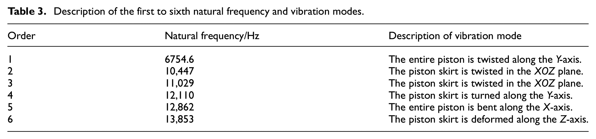
In the modal analysis of the piston, there is no need to apply a pre-stress, but only to fix and restrict the inner surface of the piston pin hole. Because the high-order modes have little effect on the vibration of the piston, this paper only studies the influence of the first to sixth modes of the piston. The first to sixth natural frequencies and vibration modes are calculated by using modal analysis. The analysis results are shown in Table 3 and Figure 9. The overall natural frequency of the piston is high, in the range of 6000–14,000 Hz. The first natural frequency is 6754.6 Hz, and the maximum deformation occurs at the piston top. At the same time, the skirt also has large deformation, and the maximum deformation of other orders occurs at the skirt.
Description of the first to sixth natural frequency and vibration modes.

The first to sixth vibration modes of the piston: (a) first order modal vibration shape, (b) second order modal vibration shape, (c) third order modal vibration shape, (d) fourth order modal vibration shape, (e) fifth order modal vibration shape and (f) sixth order modal vibration shape.
Harmonic response analysis
Harmonic response analysis is mainly used to determine the steady-state response of the structure under the dynamic load of simple harmonic motion. The harmonic response analysis in this paper is based on the modal analysis, and the frequency response curve is obtained using the method of mode superposition. The frequency response curve obtained from the study can predict the continuous dynamic characteristics of the piston structure and analyze whether the piston can successfully resist the adverse effects caused by external excitation, such as resonance, fatigue, and other harmful factors of forced vibration.
The motion equation of the structure under simple harmonic load is shown in equation (5).

Here, {F} is the amplitude vector of the sinusoidal load. θ is the excitation frequency.
The displacement response of the node is equation (6)

Here, A is the displacement amplitude vector. Φ is the phase angle of the displacement response lagging excitation load.
By using the mode superposition method to solve the harmonic problem, it only needs to set the frequency interval, the solution interval, and apply the load. According to the modal analysis results, the frequency interval is set to 6000–14,000 Hz, the solution interval is set to 80, and a pressure of 22 MPa is applied to the top of the piston. After solving the harmonic response, the displacement frequency response curves of the piston top in the X-axis, Y-axis, and Z-axis and the displacement frequency response curves of the piston skirt in the X-axis, Y-axis, and Z-axis are obtained. It is shown in Figure 10.

Harmonic response analysis results: (a) displacement frequency response curve of the piston top in the X-axis direction, (b) displacement frequency response curve of the piston top in the Y-axis direction, (c) displacement frequency response curve of the piston top in the Z-axis direction, (d) displacement frequency response curve of piston skirt in the X-axis direction, (e) displacement frequency response curve of piston skirt in the Y-axis direction, and (f) displacement frequency response curve of piston skirt in the Z-axis direction.
Figure 10(a) shows the displacement frequency response curve of the piston top in the X-axis direction. When its frequency is about 12,100 Hz, the maximum vibration displacement is 1.08 mm and then decreases. Figure 10(b) shows the displacement frequency response curve of the piston top in the Y-axis direction. The maximum vibration displacement of 5.72 mm is obtained at 12,100 Hz. When the maximum value is reached, it begins to decrease. Figure 10(c) shows the displacement frequency response curve of the piston top in the Z-axis direction. The maximum vibration displacement occurs at 12,100 Hz. After reaching the ultimate value, it begins to decrease slowly, and then there is a significant fluctuation. Figure 10(d) shows the displacement frequency response curve of the piston skirt in the X-axis direction. The maximum displacement is 0.36 mm at 12,100 Hz, and then it increases and decreases, and there are several small fluctuations. Figure 10(e) shows the displacement frequency response curve of the piston skirt in the Y-axis direction. The maximum displacement is 8.77 mm at 12,100 Hz, and then shows a decreasing trend. Figure 10(f) shows the Z-axis direction displacement frequency response curve of the piston skirt. The maximum displacement is 0.01 mm at 12,100 Hz. The curve shows an upward trend as a whole, gradually decreases after reaching the peak, and there are several small fluctuations. The displacement amplitude reaches the maximum at 12,100 Hz, where resonance is most likely to occur. To improve the operational stability of the piston and ensure the service life, the piston should avoid external excitations close to these peak frequencies during working conditions.
Multi-objective optimization design of piston
At present, multi-objective optimization is widely used in engineering practice. It can achieve the best critical position of multiple objective parameters under limited constraints. 39 The multi-objective optimization of the piston is to improve its operational performance without increasing the piston mass. 40
The optimization design flow chart is shown in Figure 11.

Optimization design flow chart.
Sensitivity analysis of dimensional parameters
The piston is roughly a cylinder, which includes many dimensional parameters, and its internal structure is also more complex. If all dimensional parameters are defined as design variables, the calculation scale will be too large. With the technicians’ suggestion of piston manufacturing enterprises, the following nine dimensional parameters are preliminarily selected, as shown in Figure 12. Then, the sensitivity analysis is carried out to determine the design variables.
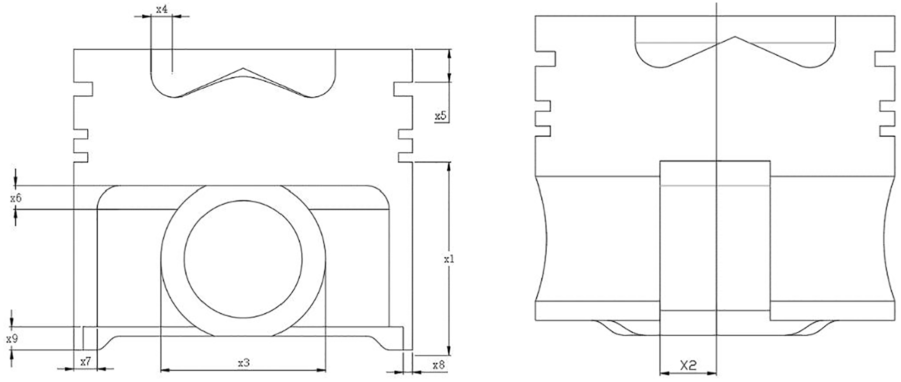
Distribution diagram of initial dimensional parameters.
Before the sensitivity analysis of the above parameters, the thermal coupling stress, thermal coupling deformation, and mass of the piston are defined as the output response of the sensitivity. Then, the sensitivity of nine dimensional parameters is analyzed by the Spearman method, and the results of sensitivity analysis are shown in Figure 13. In the sensitivity diagram, when the sensitivity value is positive, the value of output parameters will increase with the increase of dimensional parameters. When the sensitivity value is negative, it means that the value of the output parameter will decrease with the rise of the dimensional parameter. Based on the histogram of thermo-mechanical coupling sensitivity analysis shown in Figure 13, the dimensional parameter x1 has the most significant impact on the thermal coupling stress, thermal coupling deformation, and piston mass. The influence of dimensional parameters x2 and x3 on the mass of the piston is second only to the dimensional parameters x1 and x3 are greater than x2. At the same time, it also has a significant influence on the thermal coupling stress and deformation. The influence of dimensional parameter x4 on the thermal coupling deformation is second only to the dimensional parameter x1, and the effect is relatively considerable in other aspects. The dimensional parameters x5 has relatively little effect on the piston mass, but has a great influence on the thermal coupling stress and deformation of the piston.

Results of dimensional parameter sensitivity analysis: (a) sensitivity analysis of the thermal coupling stress, (b) sensitivity analysis of the thermal coupling deformation, and (c) sensitivity analysis of the mass.
Based on the above analysis, the dimensional parameters x1, x2, x3, x4, and x5 are chose as the design variables to be optimized. The range of variation and initial value of the design variable is shown in Table 4.
Range of variation and initial value of the design variable to be optimized.

When determining the variation of design variables, to ensure the regular use of the piston, assembly constraints, and other factors, the total height of the piston does not change with the change of the skirt height of the piston.
Analysis of response surface
The optimal space-filling design method is adopted in DOE experimental design for five design variables of the piston. This method has the advantages of obtaining the maximum insight into the design points with the least number of sample points and avoiding the inaccurate results caused by the excessive concentration of sample points.41,42 In the sampling process, the central composite design method is adopted as the sample type, and the total number of sample points is 27. The maximum thermal coupling equivalent stress, maximum thermal coupling deformation, and mass obtained under the initial state of the piston are taken as the main optimization objectives, and the maximum temperature of the first ring groove is added as the secondary optimization objective. The corresponding objective functions are represented by y1, y2, y3, and y4, respectively.
Based on the 27 groups of data obtained from the experiment, the response relations between the design variables and the objective functions are fitted using the multiple quadratic regression equation. The mathematical model of the quadratic response surface can be established through analysis, as shown in equations (7)–(10).
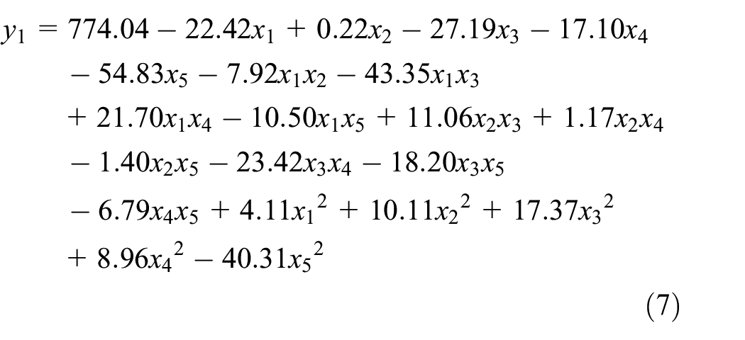


According to the above quadratic response surface mathematical equation, the response surface is established, as shown in Figure 14. There are five design variables, and Figure 14 only shows the response surface of some design variables and output variables.

Diagram of response surface model: (a) response surface of x4 and x5 with thermal coupling deformation, (b) response surface of x3 and x5 with thermal coupling stress, (c) response surface of x1 and x2 with the piston mass, and (d) response surface of x4 and x5 to the temperature of the first ring groove.
Through the response surface model Figure 14(a), the thermal coupling deformation of the piston has a negative correlation with the design variable x4 and a positive correlation with the design variable x5, in which the x4 has a more significant impact on the thermal coupling deformation of the piston. Figure 14(b) shows that the design variable x3 and x5 have a negative correlation with the thermal coupling stress. With the increase of the x5, the thermal coupling stress decreases significantly. The design variable x5 has a more significant impact on the thermal coupling stress. For the piston mass, as shown in Figure 14(c), the design variable x1 and x2 are negatively correlated with it. When the total height of the piston remains unchanged, the reduction of the skirt height has a greater impact on the mass than the reduction of the distance between the two piston pin holes, which provides a design idea for the lightweight of the piston. The temperature of the first ring groove of the piston has a negative correlation with the design variable x4 and x5, and the design variable x5 has a greater impact as shown in Figure 14(d). In general, it can be seen that the combustion chamber filet and fire land height of the piston have a more significant effect on the whole piston.
Multi-objective optimization design of the piston
The optimization problem of the piston is to determine the best balance point between the piston mass and thermal coupling equivalent stress, the thermal coupling deformation, and the temperature of the first ring groove. The overall performance of the piston is improved without increasing the mass of the piston. Multi-objective optimization is to establish and solve multiple optimization objective functions by mathematical methods under the constraints of given boundary conditions and design variables.
The multi-objective optimization model of the piston is as follows.


Where, x represents the design variable, i represents the number of design variables, min represents to find the target minimum, f(x) represents the objective function, x represents the lower limit of the design variable, and
X = [x1, x2, x3, x4, x5]T represents the five design variables as shown in Table 4.
fα(x) = y1, fβ(x) = y2, fχ(x) = y3, fδ(x) = y4 represents the thermal coupling equivalent stress, the thermal coupling deformation, the mass, and the maximum temperature of the first ring groove of the piston respectively.
The lower and upper limits of design variable are
After fitting the quadratic response surface mathematical model, the multi-objective genetic algorithm can be used to optimize the objective function. The multi-objective genetic algorithm is based on NSGA-II (non-dominated sorting genetic algorithm II). It can quickly optimize in an ample design variable space. 43 It is suitable for calculating the global maximum or minimum value. It can avoid the trap of local optimization and it uses fast sorting to find the non-dominated solution, retain the elite population, and maintain the diversity of the population. Under the conditions given by the above multi-objective optimization model, the multi-objective genetic algorithm based on NSGA-II is used for optimization, and five groups of Pareto set are obtained, as shown in Table 5.
Five groups of Pareto set.

Analysis of optimization results
The above five groups of results are the optimal design solution, which can be chosen according to the actual needs in the manufacturing process. After comprehensive consideration, the third group is chose as the result and compared with the initial data. Table 6 gives the results of the comparison before and after optimization.
Comparison before and after optimization.

The thermal coupling deformation of optimized piston is 0.159mm, which is 3.05% less than the initial value. The thermal coupling equivalent stress is 558.53MPa, which is 27.85% lower than the initial value. The optimized piston mass is 0.641kg, which is 5.46% lower than the initial design. The temperature of the first ring groove is 251.235°C, which is 12.54% lower than the initial value.
Conclusions
In this paper, the titanium alloy piston is taken as the research object, and the piston model is analyzed by finite element simulation. The equivalent stress and deformation distribution cloud chart of the piston under the separate action of the mechanical load is obtained, and the regions prone to stress concentration and deformation are found. Through the thermo-mechanical coupling analysis, the temperature field, thermo-mechanical coupling field, and deformation of the piston are obtained. The natural frequency, vibration type, and the maximum displacement frequency response of the piston are obtained through modal analysis and harmonic response analysis. The sensitivity of nine parameters was screened by the Spearman method to determine the five design variables to be optimized. The maximum thermal coupling equivalent stress, maximum thermal coupling deformation, mass, and the maximum temperature of the first ring groove are taken as the objective function. The optimal space-filling experimental design is conducted, the response surface model is built, and the correlation of the design variables with the objective function is analyzed. Then, the multi-objective genetic algorithm based on NSGA-II is used to optimize the objective function, and the Pareto set is obtained simultaneously. The results showed that the thermal coupling stress, thermal coupling deformation, mass, and the first ring groove temperature of the piston were reduced by 27.85%, 3.05%, 5.46%, and 12.54%, respectively. The thermal coupling stress and the temperature of the first ring groove decreases significantly on the premise that the piston mass does not change significantly. This study provides a theoretical basis for the optimization design of the piston.
Footnotes
Handling Editor: Chenhui Liang
Declaration of conflicting interests
The author(s) declared no potential conflicts of interest with respect to the research, authorship, and/or publication of this article.
Funding
The author(s) disclosed receipt of the following financial support for the research, authorship, and/or publication of this article: This work was supported by the Chinese National Natural Science Foundation (grant numbers 51665021, 51366006, U1960101), Yunnan Postdoctoral Research Fund in 2020.