
Abstract
This study presents two improved designs of eccentric-shaped permanent magnets and teeth-shaped stators in radial-flux dual three-phase permanent magnet electric machines to reduce cogging torque and torque ripple. The finite element analysis (ANSYS Electromagnetics) has been adopted in simulation, and real radial-flux dual three-phase permanent magnet electric machines have been fabricated in experiment to verify the study. Using the radial-flux dual three-phase permanent magnet electric machines in electric machine systems can improve the reliability and obtain higher output torque. In electrical drives and control, a simplified model-free predictive current control method has been proposed and implemented to drive the radial-flux dual three-phase permanent magnet electric machines, and the control law has been achieved by a TMS320F28377S microcontroller of Texas Instruments. The simplified model-free predictive current control method is senseless to parameter variations and back electromotive force of the permanent magnet electric machines, and only needs current sensors to detect six-phase current. The optimal one has been chosen by 14 various switching modes, which has the minimum cost function, and then the converter can be directly driven and controlled in the next sampling period. The features of the simplified model-free predictive current control method can reduce the algorithm calculation and avoid the defect of conventional model-based predictive current control scheme. A proportional-integral speed controller has also been designed to achieve the speed response of the fixed-speed tracking effect. Finally, the feasibility and effectiveness of the proposed simplified model-free predictive current control method for the dual three-phase permanent magnet electric machines can be verified in the experimental and quantitative results.
Keywords
Introduction
In recent years, permanent magnet electric machines (PMEMs) have multitudinous advantages of high efficiency, high power density, high torque density, easy servo control, stability, and low noise and vibration. The PMEMs are widely applied to drive systems of industrial and electronic products, 1 such as electric vehicles and hybrid electric vehicles, 2 robots 3 and so on. Unfortunately, the PMEMs always instinctively generate cogging torque from the interaction between magnetic poles and stator teeth shapes. The cogging torque causes noise and vibration and leads to unsteady rotation and torque ripple in the PMEMs. In other words, torque ripple can be restricted by the cogging torque reduction, and the performance of the PMEMs, for example, stability, lower vibration and noise, and so on, can be improved by decreasing cogging torque and torque ripple. Hence, the design of the PMEMs not only focuses on cogging torque reduction but also pays attention to the amplitude of torque ripple reduction. Both of them are important issues in the design of the PMEMs. The influence factors of cogging torque and torque ripple are numerous, such as machine structure, stator and rotor materials, magnetic materials, magnetic structure, and so forth. Generally, cogging torque could effectively be reduced by improved design of the PMEMs to decrease stator reluctance and adjust magnetic flux distribution of air gaps, 4 such as pole-pair number or pole-shaped design5,6 and stator skew slot design, 2 and then torque ripple could be minimized by cogging torque reduction. The permanent magnet (PM) eccentric shape design and the stator teeth shape design were efficient and effective methods in adopting PM and stator teeth geometry structure.7–11 Thus, an improved mechanical design of the PM and the teeth-shaped stator for an optimal design was presented in this study to achieve the lower cogging torque of the radial-flux dual three-phase PMEMs.
Field-oriented control combined with proportional-integral control loop is the most commonly adopted control methods for the PMEMs. Moreover, several control algorithms such as adaptive fuzzy neural network, sliding mode control, direct torque control, grey wolf optimizer, genetic algorithm and particle swarm optimization had been proposed to improve the dynamic or static response and robustness of drive systems. 12 In general, current control law is the most public control and drive systems in the PMEMs. Although model-based control has been applied to common design for wide ranges of the PMEM system, there are also several different techniques to be achieved in control system of the PMEMs. Model predictive control had also been widely utilized in other engineering applications.13–15 A model-based predictive current control (MPCC) adding a modulation stage based on a switching pattern had been proposed; it reduced the currents according to a defined cost function at each sampling period. 16 An MPCC method adopting two vectors had been proposed to control output currents with small current errors and current ripples. 17 Another MPCC method had been proposed to mitigate the generation of harmonic components in multiphase drives. 18 In addition, a model-free predictive current control (MFPCC) based on current extent and multiplied current variation was carried out for its feasibility. 19 Also, the MFPCC had been achieved in current difference detection methods. 20 The MFPCC method did not require any motor model parameters, and adopted signals of measured stator currents and computed current variations. The next stator currents for all possible conducting modes generated by the inverter could be predicted easily using the additional operation. Moreover, predictive current could have the lower total harmonic distortion (THD) by comparing with the model-free and model control methods. 21 A dual-voltage-vector model-free predictive current control (DVV-MFPCC) for synchronous reluctance motors had been proposed to compare with single-voltage vector (SVV) and the MPCC, respectively, and then DVV-MFPCC had better current-tracking performance than SVV-MPCC, SVV-MFPCC and DVV-MPCC. 22 Therefore, this article presents a simplified model-free predictive current control (SMFPCC) method for the designed radial-flux dual three-phase PMEMs. The SMFPCC is different from MPCC. 23 It required neither motor parameters nor back electromotive forces (back EMFs) of the PMEMs. The proposed SMFPCC method also did not need model parameters or back EMFs of the PMEMs while predicting currents. The predictive current could be detected and calculated easily. Generally, the conventional MFPCC method had to detect current slope by using two-time current sampling in each sampling interval. One-time current was simplified in the proposed SMFPCC method to avoid the current surge after switching changed. Referring to the previous study, 24 this article had implemented the feasibility and effectiveness of the proposed SMFPCC method by using a TMS320F28377S microcontroller for the designed radial-flux dual three-phase PMEMs. Adopting the SMFPCC method in the radial-flux dual three-phase PMEMs has advantages of low-speed operational characteristics enhancement, smooth operation, higher fault tolerance, reliability and safety. Finally, the proposed SMFPCC method had been achieved in the designed radial-flux dual three-phase PMEMs to improve better current-tracking capability with low torque ripple.
Cogging torque reduction design and analysis
A reference model of the radial-flux dual three-phase PMEM was set up in this study as a control group. Figure 1 shows the 2D cross-section graphics of the 14-pole and 18-slot radial-flux dual three-phase PMEM, where the air gap length is 0.6 mm and outer diameters of stator and rotor are 70.0 and 40.0 mm, respectively. The detailed design parameters of the radial-flux dual three-phase PMEM in this study are listed in Table 1.

The 2D cross-section graphics of the 14-pole and 18-slot radial-flux dual three-phase PMEM.
The detailed design parameters of the radial-flux dual three-phase PMEM.

PMEM: permanent magnet electric machine.
To obtain the enhanced design, two variables shown in Figure 2 were defined in this study, that is, the eccentric distance d and the teeth edge length l. Both variables could be defined clearly utilizing the improved design method of the eccentric-shaped PM and teeth-shaped stator to decide the optimal shape of the PM and stator teeth for adjusting air gap length and verify the goal of cogging torque reduction.

(a) Original design applied in the improved eccentric-shaped PM. (b) Optimal shaped design of the PM. (c) Original design applied in improved teeth-shaped stator. (d) Optimal shaped design of the stator teeth.
On one hand, cogging torque could be obtained conveniently by applying to electromagnetic finite element analysis (FEA) software in specific shape design. First, the eccentric-shaped PM was different by varying the PM eccentric distance d from 0.0 to 15.0 mm and fixing the cutting edge length l in 0.0 mm in the radial-flux dual three-phase PMEM. The PM eccentric distance d was varied for the eccentric-shaped PM, and the cogging torque, output torque and torque ripple could be obtained for different rotor positions and the PM eccentric distance d as listed in Table 2 and shown in Figures 3–5, respectively. The FEA result of the cogging torque reduction, output torque reduction and torque ripple reduction for varying the PM eccentric distance d is shown in Figure 6. Thus, the PM eccentric length d could be fixed in 15.0 mm so that the cogging torque and torque ripple could be minimized in this study. Next, stator teeth shape was also different by varying the teeth edge length l from 0.0 to 0.5 mm and fixing the PM eccentric distance d in 15.0 mm in the improved model. The teeth edge length l was varied for the stator teeth shape, and the cogging torque, output torque, and torque ripple were obtained for different rotor positions as listed in Table 3 and shown in Figures 3–9, respectively. The FEA results of the cogging torque reduction, output torque reduction and torque ripple reduction for varying the teeth edge length l is shown in Figure 10. Hence, the cogging torque and torque ripple could be minimized by the cutting edge length l fixed in 0.1 mm in this study. Finally, the optimal model, that is, ST1-P15, had been obtained in various compared models.
The FEA results of varied PM eccentric distance d.
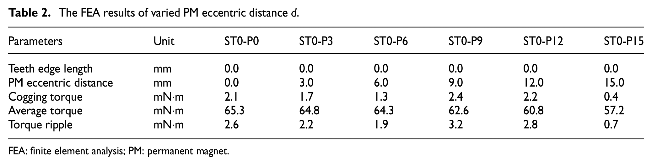
FEA: finite element analysis; PM: permanent magnet.

The FEA results of the cogging torque for varying the PM eccentric distance d.
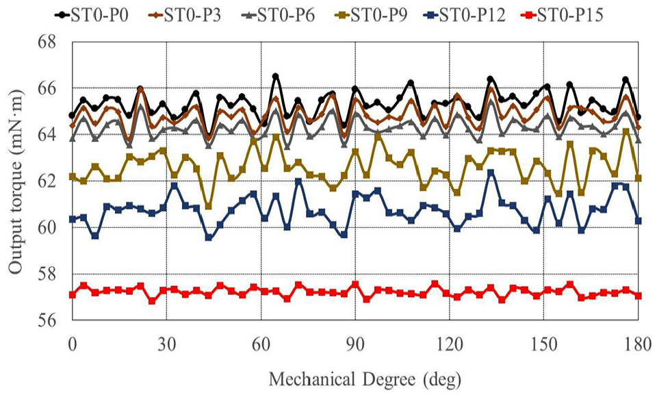
The FEA results of the output torque for varying the teeth edge length l.

The FEA results of the torque ripple for varying the PM eccentric distance d.

The FEA results of the reduction for varying the PM eccentric distance d.
The FEA results of different teeth edge length l.
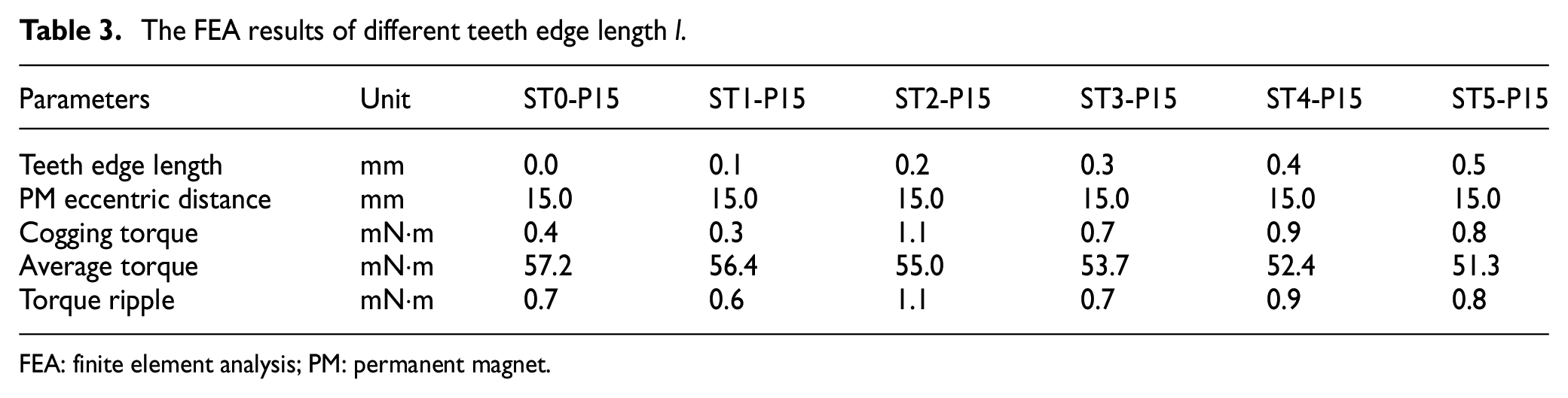
FEA: finite element analysis; PM: permanent magnet.

The FEA results of the cogging torque for varying the PM eccentric distance d.
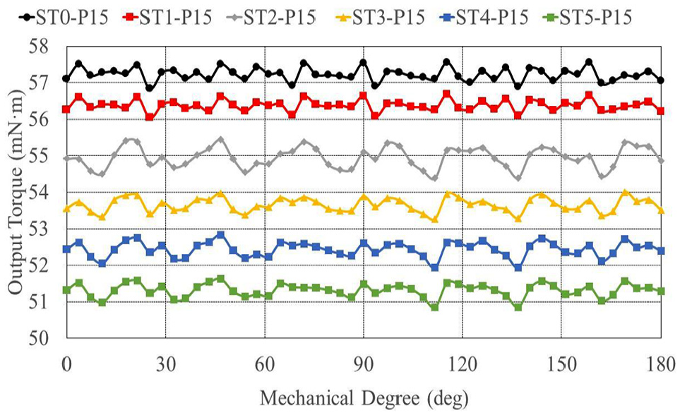
The FEA results of the output torque for varying the teeth edge length l.

The FEA results of the torque ripple for varying the teeth edge length l.

The FEA results of the reduction for varying the teeth edge length l.
The peak-to-peak amplitude of the cogging torque in comparison to the reference model and the optimal model, that is, ST1-P15, are reduced from 2.1 to 0.3 mN·m, and torque ripple were reduced from 2.6 to 0.6 mN·m. In other words, percentage reduction of the cogging torque could be up to 85.1%, and percentage reduction of the torque ripple could be up to 75.3%. The output torque was reduced from 65.3 to 56.4 mN·m. In other words, percentage reduction of the output torque could be about 13.7%. The output torque of the optimal model was more stable and smooth, relatively, than reference model, even though the optimal model had lower output torque. In experiment, the measured equipment of the cogging torque was set up in this study as shown in Figure 11. The optimal combination of the ST1-P15 was compared with the reference model of the ST0-P0 to verify the optimal design of the cogging torque reduction. It could reduce cogging torque and improve the performance of the radial-flux dual three-phase PMEM effectively. The experimental results indicated that the experimental curve of the ST1-P15 was smoother than the ST0-P0, and the peak-to-peak amplitude of the cogging torque reduction could be up to 50.0% as shown in Figure 12.
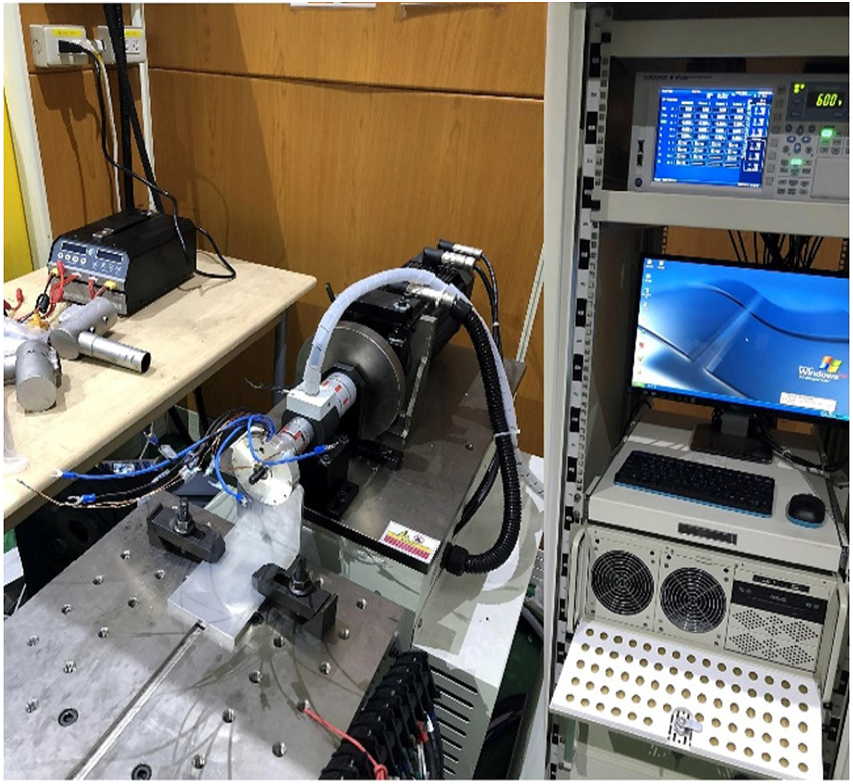
The measured equipment of the cogging torque experiment.

The experimental result of the cogging torque reduction.
SMFPCC method
To accomplish the satisfactory current-track response, the SMFPCC method based on current variation detection was achieved to drive the radial-flux dual three-phase PMEM. The principle schematic diagram of the SMFPCC method is shown in Figure 13. Because the two-time sampling period was very short, the stator current of S(k – 1) switching state in the (k – 1)th sampling period could be neglected.

The principle schematic diagram of the SMFPCC method.
The conventional MFPCC had to detect current slope by two-time current sampling in each switching interval. Because the switching interval of two-time current sampling was very short, the two sampling currents were approached. Thus, two-time current sampling could be reduced to one-time, and then two adjacent switching current errors were calculated, so the current slope was not necessary in this method. To calculate the current variation corresponding to the switching interval, the proposed SMFPCC method was sampled for the current transformation before the switching change. It was defined definitely within the switching interval of the status SW(k – 1). The corresponding dual three-phase stator current transformation follows
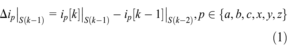
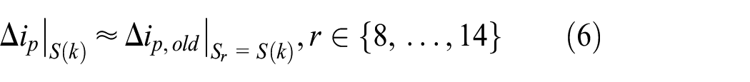
where Δip|S(k-1) means the (k – 1)th sampling interval, the subscript ‘S(k – 1)’ means the applied (k – 1) th switching state, and the symbol ‘p’ expresses the stator current in a-phase, b-phase, c-phase, x-phase, y-phase or z-phase, respectively. The switching state is the case S(k – 1) corresponding to the dual three-phase stator current variation, and then defined in the switching status S(k) and S(k + 1), the dual three-phase stator current corresponding to the switching interval of S(k) and S(k + 1) defined as follows

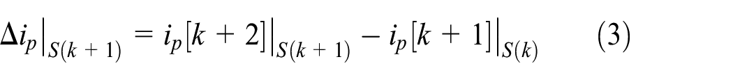
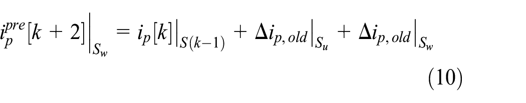
Through using equations (2) and (3), the corresponding six-phase stator current could be derived when the switching state SW(k+1) in the (k+2)th sampling interval as following

As the sampling time T is very short, the value of dual phase stator current variation, that is, Δip|S(k) and Δip|S(k + 1), can be replaced by the previous current value. That is, the following equation set up as
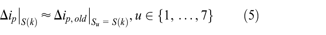


The subscript ‘old’ means the previous variation value of the dual three-phase stator current, which is the current variation measured in the adjacent sampling interval in the past. The SWu and SWw mean the (k)th and (k + 1)th of seven kinds of switching state: SW1, SW2, SW3, SW4, SW5, SW6 and SW7; and the SWr and SWt mean the (k)th and (k + 1)th of seven kinds of switching state: SW8, SW9, SW10, SW11, SW12, SW13 and SW14. Substituting equations (5) and (6) into equation (4), we can get as follows

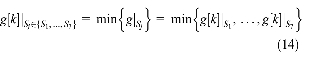
The superscript ‘pre’ means predictive current. Finally, the cost function of the SMFPCC method can be defined as


Experimental setup and results
A control system block diagram of the SMFPCC method for the radial-flux dual three-phase PMEM is shown in Figure 14(a), comprising hardware and software parts. The hardware part consists of the radial-flux dual three-phase PMEM, current sensors, current/voltage converters, A/D converters, a microcontroller and a power module inverter. The software part contains the proposed SMFPCC algorithm, a proportional-integral speed control law, angle and speed observers, and Park (d-q) and Clarke (α-β) transformation. First, given the rotational speed command, and then compared with the real rotational speed, rotational speed error can be obtained. The α1-β1 and α2-β2 current commands can be obtained via the proportional-integral speed control law and the Park (d-q) and Clarke (α-β) transformation, and then input the α1-β1 and α2-β2 current commands into the SMFPCC controller. The six switching sequences to change the switching states, that is, Sp, p∈{a, b, c, x, y, z}, could be obtained. The six-phase stator currents, that is, ip, p∈{a, b, c, x, y, z}, adjusted by different switching states fed through the current sensors, current/voltage converters, A/D converters and the Clarke (α-β) transformation, and the α1-β1 and α2-β2 currents could be feedback to the SMFPCC controller. In speed control loop, the speed error could be estimated by comparing with speed observer (ω) and the speed command (ω*), and then fed into the proportional-integral speed controller. In electrical drives and control experiment, an experimental hardware drive circuit for the radial-flux dual three-phase PMEM was constructed as shown in Figure 14(b), including nine electronic components: (A) TMS320F28377S microcontroller made by Texas Instruments; the microcontroller contains one set of TMS320C28x 32-bit CPU capable of high-speed data processing at up to 200 MHz; (B) SCM1246MF intelligent power module made by SanKen Electric Co., Ltd., with an output breakdown voltage of 600 V and output current of 30 A; (C) LA25-NP current sensors made by LEM Co., Ltd.; (D) TL084 current/voltage converter circuit made by STMicroelectronics; (E) 16-bit A/D converter circuit of AD7655 made by Analog Devices; (F) overcurrent protection circuit, and it protects against excessive current; (G) HCPL-2631 optocouplers made by Agilent Technologies; (H) encoder circuit; and (I) DC power supplies. The proposed SMFPCC algorithm created by C programming language was achieved in the TMS320F28377S microcontroller. The α1-β1 and α2-β2 current commands and corresponding responses based on the SMFPCC method in steady-state experimental results, which was operated at 500 rpm and loaded 1 N·m, are shown in Figure 15(a) and (d), respectively. The α1-β1 and α2-β2 current errors are shown in Figure 15(b), (c), (e) and (f), respectively. In addition, the α1-β1 and α2-β2 current locus diagrams and current error distribution diagrams based on the SMFPCC method in the experimental results are shown in Figure 16(a)–(d), respectively. The average current errors of α1, β1, α2, and β2 axes are 0.3458, 0.3511, 0.3511, and 0.3995 A, respectively. Current ripples of α1-β1 and α2-β2 axes are 0.4287 and 0.4583 A, respectively. The THD is 4.85%, and a lower THD means loss reduction in electric machine system. The proposed SMFPCC algorithm was verified to achieve lower average current errors and current ripples in the radial-flux dual three-phase PMEM. The experimental results can demonstrate the feasibility of the proposed SMFPCC method.
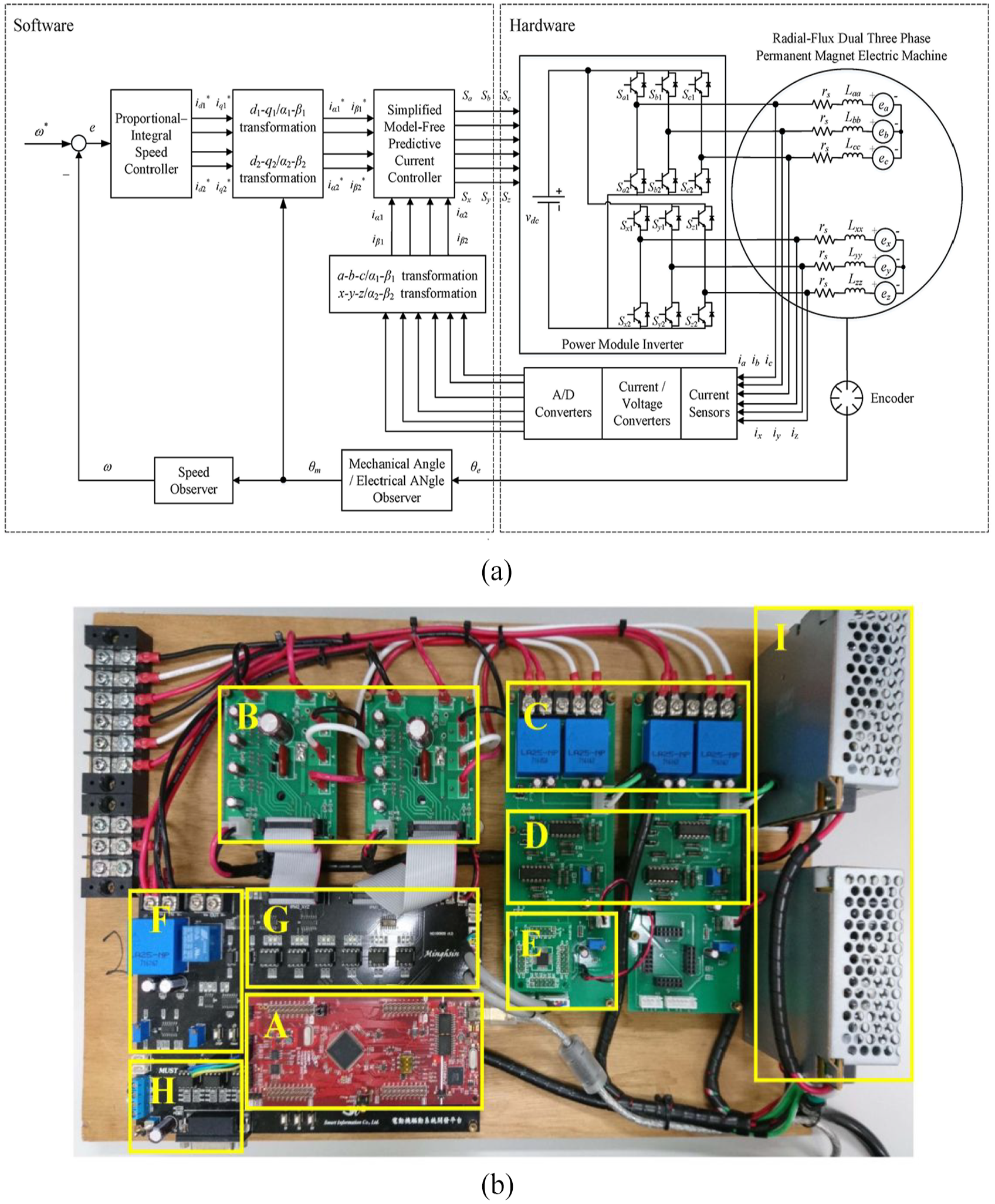
(a) The control system block diagram of the proposed SMFPCC method for the radial-flux dual three-phase PMEM and (b) the experimental hardware drive circuit for the radial-flux dual three-phase PMEM.
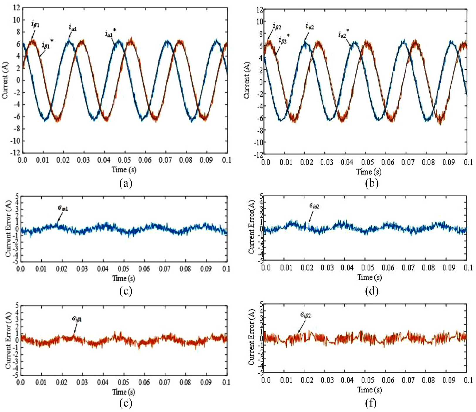
(a) α1-β1 current commands and responses, (b) α1 current error, (c) β1 current error, (d) α2-β2 current commands and responses, (e) α2 current error and (f) β2 current error based on the proposed SMFPCC method.
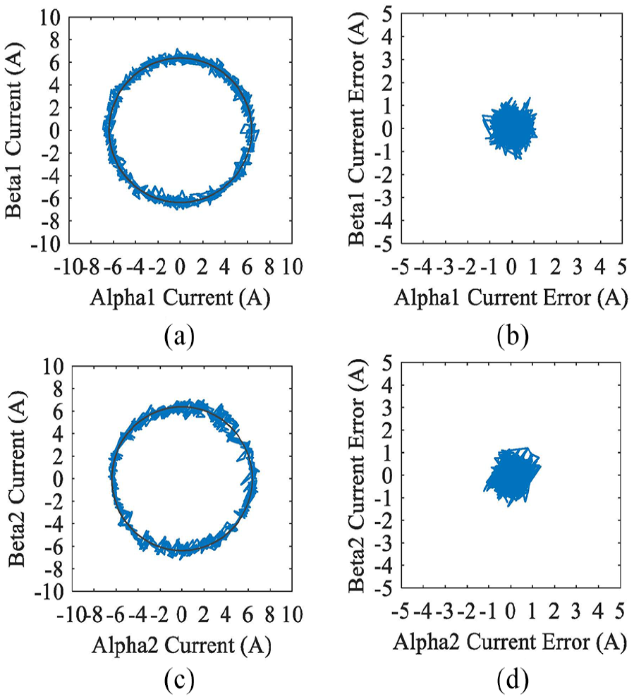
(a) α1-β1 current locus diagram, (b) α1-β1 current error distribution diagram, (c) α2-β2 current locus diagram and (d) α2-β2 current error distribution diagram based on the proposed SMFPCC algorithm.
Conclusion
The PMEMs always generate cogging torque inherently from the interaction between magnetic poles and stator teeth shape. The cogging torque causes noise and vibration, and leads to unstable output torque with ripples and unsteady rotation in the PMEMs. These issues also cause the lower efficiency and disappointing performance of the PMEMs. Thus, a design method of eccentric-shaped PMs and teeth-shaped stators is proposed in this study to achieve cogging torque and torque ripple reduction. In addition, a reference model of the radial-flux dual three-phase PMEM was set up as a control group. Two variables, the PM eccentric length d and the teeth edge length l, could be defined clearly utilizing the improved eccentric-shaped PM and teeth-shaped stators to decide the geometry structure design and verify the goal of cogging torque and torque ripple reduction in the PMEMs. The finite element analysis (FEA) software, that is, ANSYS Electromagnetics, was adopted in simulation, and compared with the cogging torque and torque ripple reduction and performance of the radial-flux dual three-phase PMEMs. In FEA simulation results, the optimal design could be obtained quickly and reliably, and the optimal teeth shape design, that is, ST1-P15, was not only resulted in cogging torque reduction from 2.1 to 0.3 mN·m but also led to torque ripple reduction from 2.6 to 0.6 mN·m; in other words, percentage reduction of the cogging torque and torque ripple could be up to 85.1% and 75.3%, respectively. In the experimental result, the percentage reduction of cogging torque could be up to 50.0%. In drive and control part, the algorithm of the proposed SMFPCC method for the radial-flux dual three-phase PMEMs is achieved in a TMS320F28377S microcontroller of Texas Instruments. There are two main contributions in this study. (1) The proposed SMFPCC method is achieved in a digital signal processor–based (DSP-based) system. The SMFPCC method only detects current variation of six-phase excitation that can be adopted to improve non-repeatability and senseless parameters of electric machines. Model-free status can avoid errors and uncertainty of parameters causing poor current tracking, so model parameters or back EMFs are not needed to drive and control the electric machines. (2) The proposed SMFPCC algorithm is validated in the dual three-phase PMEMs. Compared with common three-phase PMEMs, the mechanism of the dual three-phase PMEMs has one more set of three-phase windings. The dual three-phase PMEMs have higher output torque and better reliability than the PMEMs. While one set of three-phase windings is damaged, another set can keep operating in rotation to avoid inoperative conditions. In the experimental results, the average current errors of α1, β1, α2, and β2 axes are 0.3458, 0.3511, 0.3511, and 0.3995 A, respectively. Current ripples of α1-β1 and α2-β2 axes are 0.4287 and 0.4583 A, respectively. The THD is 4.85%. The proposed SMFPCC method is validated to achieve better current-tracking performance in the radial-flux dual three-phase PMEM. Finally, there are three points for future developments and applications: (1) Other robust controller combination, for example, neural network, sliding mode control, H-infinity method, direct torque control, predictive torque control and so on; (2) firmware programming optimization and hardware equipment upgrade, for example, multi-core DSP, programme simplification and computational efficacy improvement; and (3) increase voltage vector quantity to achieve better tracking effect, for example, two voltage vectors and three voltage vectors.
Footnotes
Acknowledgements
The authors would like to acknowledge Mr. Yongxin Wang who comes from Maritime College, Guangdong Ocean University, Zhanjiang, China, for debugging control algorithm and help on experimental implementation. The authors would like to thank the reviewers for their constructive suggestions, which greatly improved this article.
Handling Editor: Xiaodong Sun
Declaration of conflicting interests
The author(s) declared no potential conflicts of interest with respect to the research, authorship, and/or publication of this article.
Funding
The author(s) disclosed receipt of the following financial support for the research, authorship, and/or publication of this article: This work was supported by the Ministry of Science and Technology of Taiwan, R.O.C., under Grant No. MOST 108-2221-E-019-035.