
Abstract
A novel dual air-gap transverse-flux six-phase permanent magnet electric machine using C-shaped configured architecture with laminated silicon steel is designed and implemented in this study. The magnetic flux density distribution and magnetic flux linkage of the C-shaped configured architecture with laminated silicon steel have been achieved to verify the design concept which leading the magnetic line in the same direction as laminated silicon steel arrangement. The notches on both stators and rotors are designed aiming at lowering down cogging torque and compared with a normal permanent magnet electric machine. The optimal combination is resulted in the cogging torque reduction of 70.2%, and the output torque reduction is 6.5%. Additionally, a new model-free predictive current control, insensitive to parameter variations of the electric machines, is proposed to drive the permanent magnet electric machine aiming at six-phase current error reduction within 0.36 A. As a result, a better satisfactory current tracking ability of the proposed model-free predictive current control law in the six-phase permanent magnet electric machine has been validated successfully in experimental results.
Keywords
Introduction
Recently, permanent magnet electric machines (PMEMs) are widely applied in high-performance motor drive applications due to desirable advantages of higher torque density and efficiency, so they have been applied in high-level servo drives, electric vehicles, medical assist devices, and so on. With the view to modify enhanced flux density and minimized volume of the PMEMs, air-gaps between rotors and stators are reduced to the minimum. Based on the same reason, the stator construction also has to be adjusted. In addition to dimension and efficiency, the output torque is an important specification. A good-performance PMEM not only emphasizes high torque output but also minimizes cogging torque. The cogging torque is cause of inherent interaction between the stators and magnetic poles of the rotors, that is, air-gap magneto-resistance and flux. The abhorrent vibration and acoustic noise are always concomitant appearance from the changes of the flux; even dynamic performances are shriveled. Many researches have been investigated in the literatures to reduce the cogging torque including design of the following: arc structures on stators or rotors,1–3 notched features of stators or rotors.5–7 The arrangement of permanent magnets (PMs) for the adoption of notches can obtain cogging torque reduction and magnetic flux decrement. Thus, a satisfying design is rooted on a desirable balance between the cogging torque reduction and magnetic flux decrement. However, the notches are not only on the rotor but also on the rotor. A new configured architecture design of C-shaped slots with laminated silicon steel doubles magnetic flux and action area in the air-gap. The coil-winding on the axial side is able to minimize the thickness of the PMEM. There are several different types of magnetic flux paths on silicon steel to improve the requirement of the torque and efficiency, and all designs could group up the magnetic flux. Hence, this article presents a novel dual air-gap transverse-flux six-phase PMEM with the C-shaped laminated slots and low cogging torque. Notches on both the stators and the rotors are designed to accomplish the target of cogging torque reduction. Various notched structures on both the stators and the rotors can be obtained by adopting finite element analysis (FEA) electromagnetic simulation through modifying magnetic flux distribution of pole faces across air-gap to reduce the cogging torque. The major factor of improving efficiency is PM usage. Therefore, the FEA electromagnetic simulation method is utilized to find out the optimal combination of PMs and stator teeth (ST) so as to satisfy the desired specifications which decreasing PM usage and maintain the output torque decrement as low as possible. Because of cost, reliability, robustness, and maintenance-free operation for PMEMs, six-phase PMEMs could be more suitable than three-phase PMEMs apparently. Nowadays, six-phase PMEMs are singular standard for electric vehicles and propellers applied in low-voltage or high-power fields with reassuring safety. There are many literatures proposed multi-phase drives with dual three-phase PMEMs, and it indicates that output torque of the PMEMs are superior to that of normal three-phase PMEMs,8,9 In general, dual three-phase PMEMs can be considered as two promising alternatives to the six-phase PMEMs when there are achieving better performance. As usual, six-phase PMEMs operating with six-phase drivers/inverters are selected by their low torque ripples. The six-phase PMEMs proposed in many researches have the same stator structure as dual three-phase PMEMs, but the six-phase PMEMs can restrict into dual three-phase or six-phase PMEMs, respectively, by adjusting winding terminals between two three-phase windings. In drive control part, a model-free predictive current control (MFPCC) method is different from model-based predictive current control, and it requires neither motor parameters nor back-electromotive force,10,11 The current difference detection technique is based on the assumption that the stator current during each switching interval is linear. As a result, the stator current difference within each switching interval can be precisely calculated. In fact, the stator current needs to be detected twice during each sampling interval. Two measured currents are sampled before and after switching state of commutation in electric machine drivers, and then the next state can be obtained by a minimum cost function. Therefore, a simplified MFPCC approach is implemented applying in the six-phase PMEM in this study to improve and achieve better current track capability.
Dual air-gap transverse-flux six-phase PMEM with C-shaped laminated slots
The interspace where magnetic flux passes through between the PM rotor and the stator is the air-gap. The dual air-gap transverse-flux six-phase PMEM consists of dual air-gaps in axial sides, 24 C-shaped laminated slots in a stator, and 20-poles in a PM rotor. A computer-aided design/computer-aided manufacturing (CAD/CAM) structure and an experimental prototype of the dual air-gap transverse-flux six-phase PMEM are shown in Figure 1(a) and (b), respectively. The design parameters and symbols of the six-phase PMEM in detail are shown in Table 1 and Figure 2, respectively. The six-phase PMEM drive system and the six-phase winding arrangement are illustrated in Figures 3 and 4, respectively. In this study, there are dual three-phase windings in the dual air-gap transverse-flux six-phase PMEM. Every three-phase angle is differed from 120° in electrical angle, that is, A, B, C, and X, Y, Z. Furthermore, the phase difference between the phase windings of A, B, C and the X, Y, Z differs from 30° in electrical angle. The magnetic flux density distribution and magnetic flux linkage of the PMEM are simulated adopting the FEA electromagnetic simulation software as shown in Figure 5(a) and (b), respectively. Dual-direction magnetic circuits of the C-shaped laminated slots in the stator can increase magnetic flux utilization and air-gap action area. By utilizing transverse-flux stator technology with dual air-gap, the cogging torque can be improved effectively. The simulation results are provided to verify the magnetic force line between the rotors and the stators which can be modified using the C-shaped laminated architecture design. Figure 5(b) shows the magnetic flux linkage arranging inside the stator for lowing cogging torque, and then machine vibration and operational characteristics of the dual air-gap transverse-flux six-phase PMEM can be improved by FEA electromagnetic simulation results. The vibration is derived by the cogging torque; thus, cogging torque reduction is crucial in torque ripple-sensitive applications. Persuasive techniques include stator reluctance reduction and air-gap magnetic flux distribution adjustment between the ST and the PMs, for example, notches on the ST or the PM rotors. Nevertheless, the notches are singly on the stator or the rotor but not both. No precedent has been done to notch on both ST and PM. In order to increase the operation of magnetic flux distribution and enhance the reduction of cogging torque, specialized notches featuring in different widths and numbers on the surface are presented and discussed as follows.

(a) A CAD/CAM structure and (b) an experimental prototype of the dual air-gap transverse-flux six-phase PMEM.
The detailed design parameters of the dual air-gap transverse-flux six-phase PMEM.

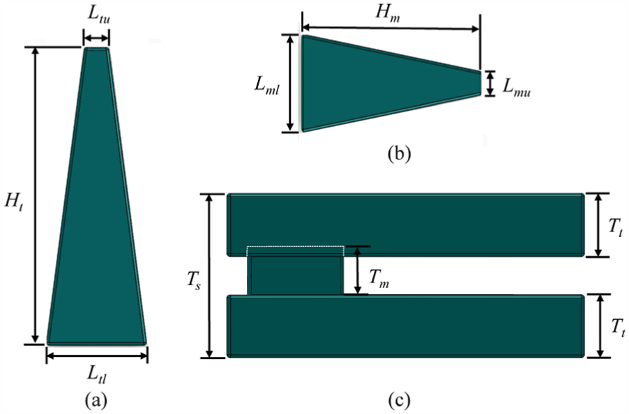
(a) Main trapezoidal stator teeth structure, (b) middle trapezoidal stator teeth structure, and (c) whole stator teeth structure.

The drive system of the dual air-gap transverse-flux six-phase PMEM.

The winding arrangement of the dual air-gap transverse-flux six-phase PMEM.

(a) Magnetic flux density distribution and (b) magnetic flux linkage of the dual air-gap transverse-flux six-phase PMEM.
Notched permanent magnet rotors and ST
To reduce the cogging torque and enhance the utilization of the magnetic field on the six-phase PMEM, four varied notches of the ST and the PM rotors in feasibility are considered as shown in Figures 6 and 7, respectively, where w1 = 1 mm and w2 = 2 mm denote the different widths of the notches. It is worth noting that the depth (d) of each notch is fixed as 1 mm. Four different notched ST with varied notch numbers in the same depth, labeled as the ST-1 to the ST-4, are shown in Figure 6(a)–(d), respectively. As similar to the ST design, the PM rotors with three notches labeled as the PM-1 and PM-2 are shown in Figure 7(a) and (b), whereas ones with five notches denoted as the PM-3 and PM-4 are shown in Figure 7(c) and (d), respectively. In FEA electromagnetic simulation, there are 16 groups of results from various permutations of the PM rotors and the ST design. The reduction rate of cogging torque with various notched in the ST and the PM rotors is shown in Figure 8(a) and (b), respectively. According to the FEA electromagnetic simulation results, the ST-4 is chosen to arrange the PM-3 in pairs to be an optimization for the reason that the waveform of the cogging torque of the ST-4 is similar to the normal structure. As tiny widths and more notched numbers leading the lower cogging torque, the PM-3 and the ST-4 which are attaining the optimal goal of 70.2% reduction of the cogging torque are chosen to arrange in pairs. The arranging pair of the PM-3 and the ST-4 report the innovative achievement with notched on both the ST and the PM. Although previous studies have reported the loss of PM usage which makes the output torque decreasing, the decrease rate of the output torque in the optimal PMEM is 12% in compare with the normal PMEM as shown in Figure 9. The objectives of reducing cogging torque are shown to be achievable through the simulations.

Different notches on the ST design: (a) ST-1, (b) ST-2, (c) ST-3, and (d) ST-4.

Different notched design on the PMs: (a) PM-1, (b) PM-2, (c) PM-3, and (d) PM-4.

Percentage reduction of the cogging torque with various notched models of (a) ST and (b) PMs.

The output torque comparison between the normal PMEM and the optimal PMEM.
Simplified MFPCC method
To accomplish satisfactory current track response, a simplified MFPCC method based on current variation detection is achieved to drive the dual air-gap transverse-flux six-phase PMEM. The principle schematic diagram of the simplified MFPCC method is shown in Figure 10. Because two-time sampling interval is very short, that is, the sampling current is very close, two-time sampling currents are changed to one-time sampling current. To calculate the adjacent corresponding current error after the two-time switch, the current slope is not necessary to be calculated. To take current measurements in the (k)th sampling interval to be an example, two currents ip[k, 1] and ip[k, 2] are detected and simplified as ip[k], where the symbol p expresses the stator current in a-phase, b-phase, c-phase, x-phase, y-phase, or z-phase, respectively. During a conduction of the applied (k – 1)th switching state, the corresponding current variation, denoted as Δip, can be expressed as follows

where


The principle schematic diagram of the simplified MFPCC method.
The corresponding six-phase stator current can be obtained by using equations (2) and (3) when the switching state is SW(k + 1) in the (k + 2)th sampling interval as follows

As the sampling time T is very short, the value of six-phase stator current variation, that is, Δip|SW(k) and Δip|SW(k + 1), can be substituted by the old value as expressed as


The subscript old means the old variation value of six-phase stator current, which the current variation has been measured in the adjacent sampling interval in the past. The SWu and SWw mean the (k)th and (k + 1)th of seven kinds of switching state SW1, SW2, SW3, SW4, SW5, SW6, and SW7, respectively. The switching state SWu must be equal to SW(k) and relative to the (k)th switching state; the SWw is unknown, so SW(k + 1)means seven kinds of switching state. The value of six-phase stator current variation from equations (5) and (6) are substitution for equation (4), the six-phase stator current can be obtained as follows

The superscript pre means predictive current. Finally, the cost function of the simplified MFPCC method can be defined as


Experimental setup and results
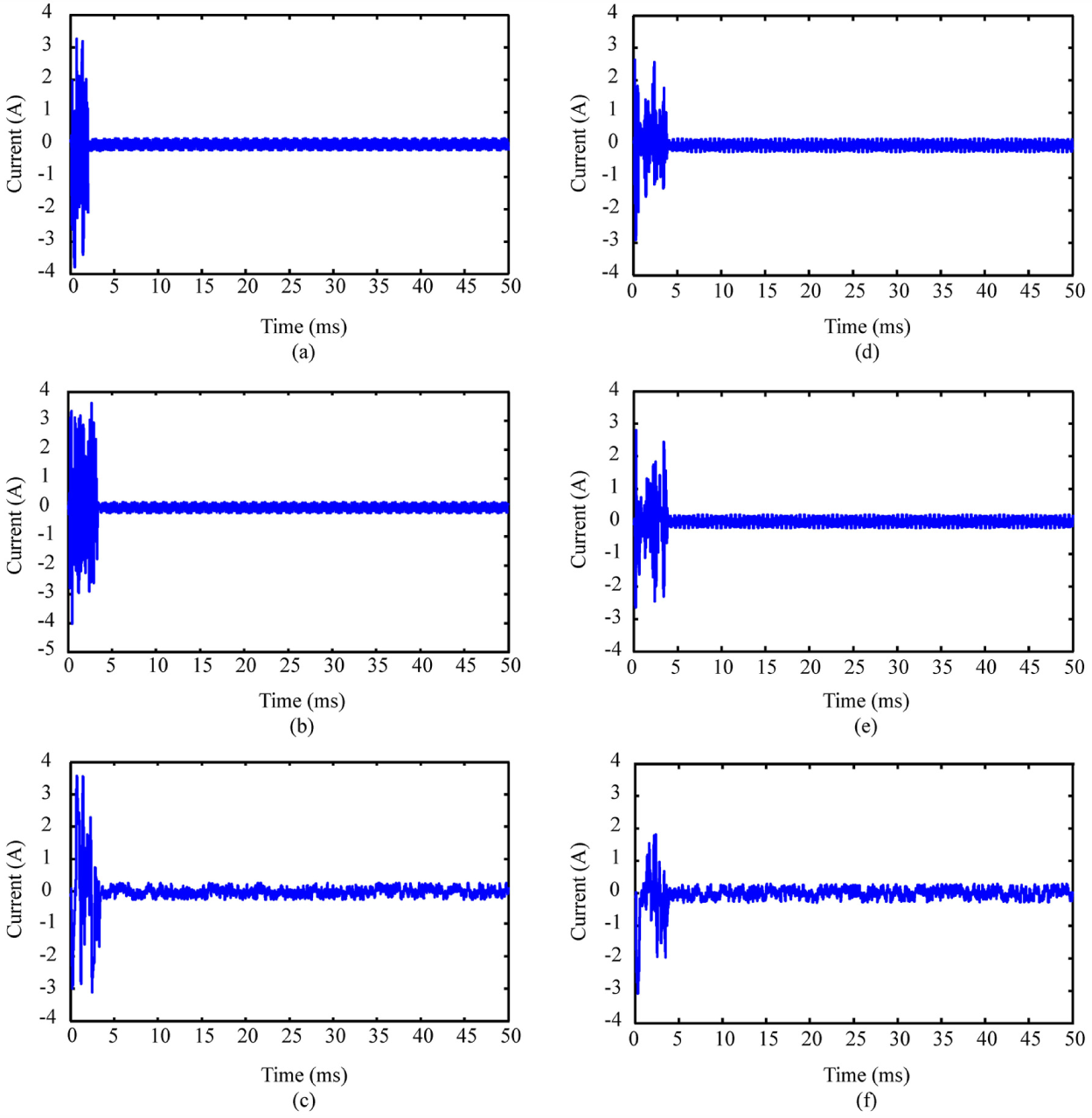
An experimental hardware equipment and setup for driving the dual air-gap transverse-flux six-phase PMEM is developed and constructed as shown in Figure 11(a). Six-phase currents are detected by current sensors from the six-phase PMEM and passed into analog-to-digital converters and then forwarded to a PC-based controller with the proposed MFPCC algorithm. The designed MFPCC algorithm created by MATLAB/Simulink is achieved in the PC-based controller. A block diagram of the dual air-gap transverse-flux six-phase PMEM with the simplified MFPCC approach is shown in Figure 11(b). The six-phase current commands varied from −5.0 to 5.0 A with a period of 25 ms (i.e. 40 Hz) and their corresponding responses based on the simplified MFPCC method in experimental results are shown in Figure 12(a)–(f), respectively. Finally, the six-phase current errors based on the simplified MFPCC method in the experimental results are shown in Figure 13(a)–(f), respectively. All current errors of the six-phase excitation are converged within 0.36 A. The proposed MFPCC method is demonstrated feasibility in the experimental results.
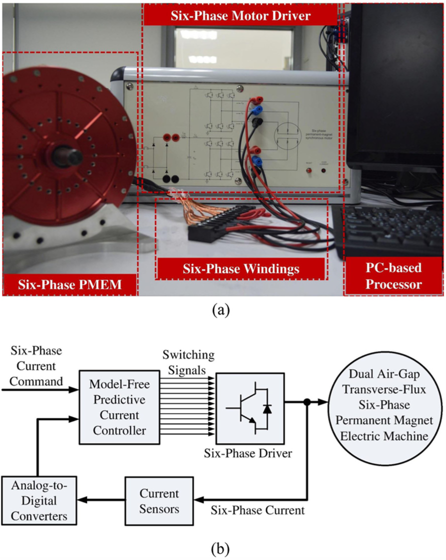
(a) An experimental hardware equipment and setup for driving the dual air-gap transverse-flux six-phase PMEM and (b) a block diagram of the dual air-gap transverse-flux six-phase PMEM with the proposed MFPCC method.

Experimental results showing the current commands and responses based on the proposed MFPCC method in (a) a-phase, (b) b-phase, (c) c-phase, (d) x-phase, (e) y-phase, and (f) z-phase.
Experimental results showing the current errors based on the proposed MFPCC algorithm in (a) a-phase, (b) b-phase, (c) c-phase, (d) x-phase, (e) y-phase, and (f) z-phase.
Conclusion
This article presents a novel dual air-gap transverse-flux six-phase PMEM with the C-shaped laminated slots and low cogging torque. Notched design on both stators and rotors is accomplished to reduce cogging torque. A prototype of dual air-gap transverse-flux six-phase PMEM using C-shaped slots with laminated silicon steel and various notches on both ST and PMs has been fabricated to achieve the goal of low cogging torque. With three-dimensional FEA electromagnetic simulation, the purpose of cogging torque reduction in varied notch numbers on the ST and the PM rotors can be solved and found out a suit for desired cogging torque decrement. In the FEA electromagnetic simulation results, an optimal percentage reduction of the cogging torque in the six-phase PMEM combined with ST-4 and PM-3 is estimated up to 70.2%. Due to the PM usage trimming, the decrease rate of the output torque is 6.5%, compared with a normal structured PMEM. Moreover, a simplified MFPCC method only detects current variation of six-phase excitation that can be adopted to improve non-repeatability and senseless parameters of electric machines. The proposed MFPCC algorithm created by MATLAB/Simulink is achieved in a PC-based controller. In the experimental results, the current errors of the six-phase excitation are converged within 0.36 A, and the proposed MFPCC method is validated to achieve better current tracking performance.
Footnotes
Acknowledgements
The authors would like to thank the reviewers for their constructive suggestions, which greatly improved this article.
Handling Editor: Tian Han
Declaration of conflicting interests
The author(s) declared no potential conflicts of interest with respect to the research, authorship, and/or publication of this article.
Funding
The author(s) disclosed receipt of the following financial support for the research, authorship, and/or publication of this article: This work was supported by the Ministry of Science and Technology of Taiwan, R.O.C. under grant no. MOST 103-2221-E-019-045-MY2, 105-2221-E-019-027, 106-2221-E-019-053, and 106-2221-E-019-070.