
Abstract
Impacting between the multilayer Kelly bar and the power head has a detrimental effect on the drilling system and may cause huge losses to the construction engineering and machinery. This study is a further development of the vibro-impact mechanism, and especially, the study considers the constraint of the steel rope on the multilayer Kelly bar. Efficient analytical models are presented, and the total responses are obtained. Three types of displacement response are found by changing the matching relationship of global parameters. The first type has the optimal vibration control performance with the shortest path and no periodicity. The second type is inferior to the first type. The third type has the worst vibration-control performance with the longest path and periodicity. Then this article proposes the general feasibility to get the first type of displacement response and the most effective way is controlling the steel rope velocity. The research provides the foundation for the intelligent control of steel rope velocity on the rig machine.
Introduction
The Kelly bar, which is usually more than 10 tons, is designed as a telescopic and multilayer pipes structure. The pipes’ weight is loaded on the power head in the form of instantaneous impacting when the pipes stretch out. The impacting repeats frequently when the rig works. Usually, the pipes fall freely at any time, and the impacting is extremely destructive to the power head. The vibro-impact after the impacting may cause deformation, weld cracking, and oil leakage. In order to reduce losses, it is necessary to check the quality of the power head. 1 It is very important to prevent and control the vibro-impact.
The vibro-impact usually results in an uncertain response. Some special excitations make the vibration system uncertain and chaotic, and the response usually has the bifurcation.2–5 Luo et al. 6 and Yue et al. 7 analyzed periodic motion and bifurcation phenomenon of the dynamic response by Poincaré map based on the vibro-impact system with 2 or 3 degree of freedom. Liu et al.8,9 studied the non-continuous grazing bifurcation behavior based on the periodic motion of a 3-degree-of-freedom vibro-impact system. Liu et al. 10 studied the vibro-impact in a tank laying on water and established the attractor to avoid bifurcation by the means of displacement feedback control, so as to achieve the control of forward and backward motion of the tank. For the purpose of vibration control, the absorber could be added in the process of vibration transmission by passive control to obtain the reasonable response. 11 The characteristic parameters could be changed by active control to improve the response performance in the vibro-impact system. 12 Harvey et al. 13 applied both isolation and absorption methods to control the vibro-impact at the same time. The study was verified on a device that constrained displacement and acceleration. In a constrained vibro-impact system, the force and the energy were transferred to the object providing the constraint, as well as a huge change of vectors such as velocity and acceleration.14–21 In a multi-degree-of-freedom vibro-impact system, the response behaviors were correlated and coupled, and the solution of the motion equations were more complicated. Xue and Fan 22 and Fan and Yang 23 studied the 2-degree-of-freedom vibro-impact system with multiple constraints and analyzed the periodic response of the system after establishing the boundary conditions.
Previous studies focused on the theoretical basis of generalized abstraction. This article pays more attention to solving major engineering problems in specific applications. The study provides a further development of the vibro-impact system with multi-degree of freedom. In this work, the dynamic model of vibro-impact is established with the constraint of the steel rope especially, and the influence of related parameters is analyzed according to the source and transmission process of vibration. The study focuses on the total response considering the global parameters. The analysis is undertaken to improve the optimum design. The result could provide foundation for the intelligent control about steel rope velocity.
Problem statement, dynamic model, and formulation
Figure 1 shows the rotary drilling rig assembly and the vibration control system of the power head. When the rig is working, the first layer pipe extends downward with the steel rope at a certain speed. At last, the first layer pipe moves with the power head. If the hole is deep enough, the subsequent impacting of each pipe takes place at the bottom. What we expect is to suppress the periodicity or to reduce the maximum displacement in the vibro-impact so as to reduce the sliding friction displacement and reduce wear. What is more is that the expectation is realized by making the structure compact, lightweight, and material saving in the case of reasonable reduction of the displacement response. Figure 2 shows the dynamic models about the vibro-impact system. The differential equation of motion for the vibro-impact can be expressed as

where

Rotary drilling rig assembly and vibration control system of the power head for vibro-impact.

Dynamic models of the vibro-impact system: (a) impacting of the first layer pipe and (b) impacting of the nth layer pipe.
The piecewise analysis is used to establish the differential equation. Before the impacting, the first pipe with the mass
First, considering the vibro-impact between the first layer pipe and the power head according to Figure 2(a). The displacement response without constraint is expressed as follow

where
The weight of the first layer pipe is considered as a step excitation with

where

In order to correct the model, the constraint of the rope is introduced into the equations with the correction parameter

The new equation of the step-excitation response becomes

The new total response of the vibration control system is obtained

Then the

The initial conditions are given by

where
Numerical investigation
Setting the value of some parameters,

Relationship between total response and steel rope displacement: (a)
After introducing the correction parameter

Relationship between total response
As shown in Figure 4, the curve of the total displacement response is significantly correlated with the curve of the rope displacement as the parameter
Now considering whether
The six groups of data for numerical investigation and the value of

FSSP: final static stable position.

Total response corresponding to the parameters in Table 1 and the value of
It shows that the value of
The first type of displacement response
Generally, the value of

The flows of the velocity about the total response are shown in Figure 6, which corresponds to the first type of displacement response.
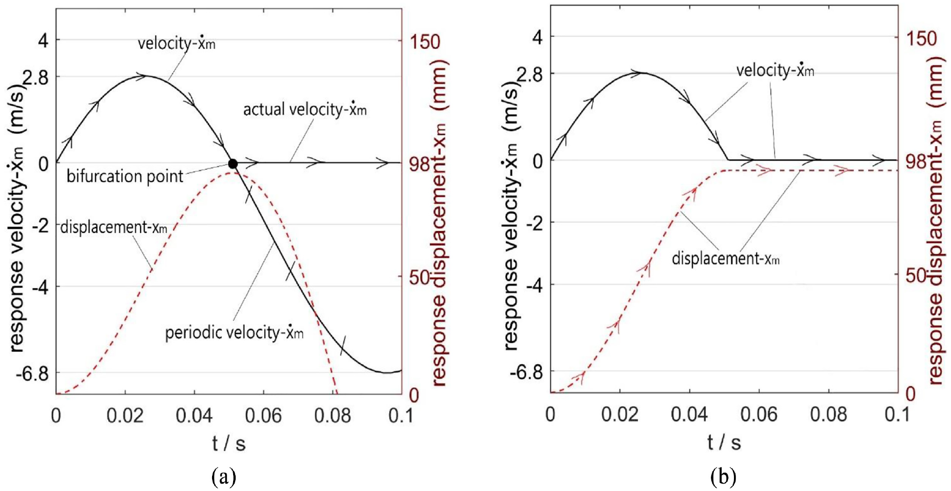
Flows of the velocity in the first type of displacement response: (a)
An important result is gained when the displacement response reaches the final static stable position (the peak) for the first time according to Figure 6(a). The velocity is zero, and its path presents a bifurcation point. Obviously, constrained by the steel rope, the velocity bifurcation point is exactly the final static stable position, and the velocity no longer changes when no external force is in the system, and as well as the displacement response will be kept at zero. Figure 6(b) shows the actual flow of the velocity with the constraint of the steel rope. Therefore, in the first type of displacement response, the direction of the displacement does not change, nor does the direction of the velocity, and the vibration control system eventually approaches the final static stable position. So the vibro-impact has no cyclic motion, less frictional loss, and shorter motion path.
The second type of displacement response
The second type of displacement response is carried out in Figure 7(a) according to the third group of data in Table 1. The velocity is faster, and the displacement response is easier to catch up with the rope displacement. The velocity is 2 m/s where the displacement curve is tangent to the rope displacement curve, which is the same as the initial value of the rope velocity. Then the vibration control system moves synchronously with the rope to the final static stable position, and the vibration control system has a non-zero initial condition

Relationship between velocity and displacement: (a) in the second type of displacement response,
The third type of displacement response
The third type of displacement response is carried out in Figure 7(b) according to the fifth group of data in Table 1. The velocity is slower, and the displacement response will no longer catch up with the rope displacement after the first impacting. Then the free-falling impact without the constraint of the rope appears. Due to the increase of initial value
The total displacement response and the type of displacement response are obtained in Table 2 and Figure 8 according to Figure 2(b).
The data of some parameters for numerical investigation in the impacting between the second pipe and the power head and the conclusion about the type of the displacement response.

FSSP: final static stable position.

(a) Total displacement response of
The displacement responses of
Figure 9 is obtained by changing the value of

(a) Displacement response according to different values of
Figure 10 is obtained by changing the value of

Decision about the type of displacement response by changing the value of
On the whole, decreasing the value of
Results and discussion
Various parameters need to be reasonably selected and predicted. After putting forward the definition of three types of displacement response, in the same condition about the final static stable position
In the first type of displacement response, the best vibration control system and steel rope velocity can be obtained. This article gives a method for determining the type of displacement response, as shown in Figure 11. According to this method, the design of the power head vibration control system and the best configuration of the steel rope velocity are guided.

Overall research methodology of this article.
Engineering example
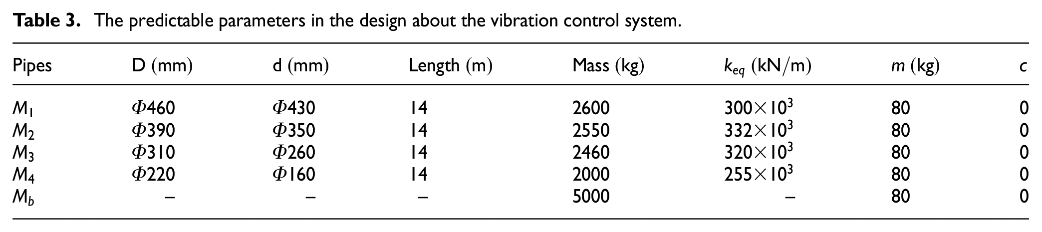
The example is proposed according to the engineering requirements. The rotary drilling rig is equipped with 4-pipe Kelly bar. Each pipe is
The predictable parameters in the design about the vibration control system.
The analysis is carried out in two cases, namely impacting of one by one and impacting of total weight on the power head.
Impacting of one by one
The purpose of the optimization is to obtain the best first type of displacement response, which is related to the final static stable position.
Table 4 shows that
Conclusion about the type of the displacement response in the impacting.
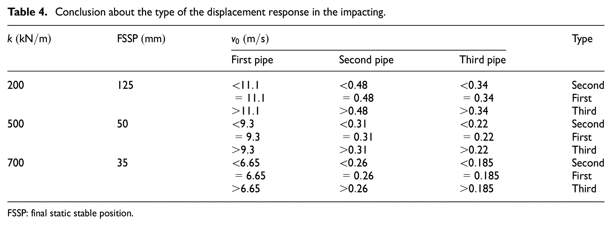
FSSP: final static stable position.
The Kelly bar includes four pipes. If the rig works normally, the innermost fourth pipe with the drilling tool will never provide the impacting on the power head. Only three pipes are loaded on the vibration control system when the fourth pipe stretches out. The maximum elastic motion range of the vibration control system is

Taking
Impacting of the total weight on the power head
This situation is fault prevention, and it often occurs in the case that the pipes are stuck and the pipes suddenly fall without any constraint. The most serious situation in the impacting is that the total weight of all pipes with drilling tool affects the system. According to the analysis of the third type of displacement response with the worst vibration control performance, the system needs to bear the total weight of H height free-falling impact, and the displacement response is shown in Figure 12.

The response about total weight of
Figure 12 shows that the displacement response varies from

The response about total weight of
When
Result of the example
These conclusions are drawn through the verification of this example. (1)
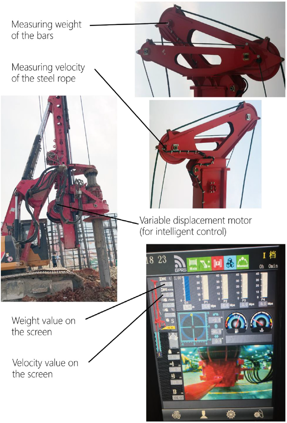
Figure 14 shows the practical example. The structure uses 10 parallel springs (total equivalent elastic coefficient

Engineering application example of vibration control system for the power head: (a) vibration control module: 10 parallel springs, (b) power head assembly, (c) two parallel elastic buffers, and (d) application of the rotary drilling rig.
Figure 15 shows the mechanism of intelligent control for the first type of displacement response which is the best vibration control method depending on the rope velocity and bars weight. This method function is realized by programming.
Mechanism of intelligent control for the first-type displacement response.
From the application point of view, more working conditions and parameters may appear. Using the research method proposed in this article, similar results can be obtained by changing the parameters. It can guide us to design an optimal vibration control system and better intelligent control of steel rope speed.
Conclusion
In this article, the influence of the various relevant parameters in the vibration source and the vibration transmission process is considered comprehensively. The dynamic model of the vibro-impact is proposed. The correction parameter
Footnotes
Handling Editor: James Baldwin
Declaration of conflicting interests
The author(s) declared no potential conflicts of interest with respect to the research, authorship, and/or publication of this article.
Funding
The author(s) received no financial support for the research, authorship, and/or publication of this article.