
Abstract
In this article, a nonlinear model predictive control algorithm for a micro-turboshaft engine is designed. The control effect is verified by a bench test. First, a micro-turboshaft engine test bench is built, and the open-loop control experiment was carried out on it. Based on experiment data, a linear parameter varying prediction model is established. Then, by online rolling optimization based on multistep output prediction, together with feedback correction, a nonlinear model predictive control algorithm is obtained. The influence of algorithm parameters on the control effect is studied, and reasonable prediction period M, control period N, and control coefficient R are designed. Finally, the application of nonlinear model predictive control in micro-turboshaft engine is verified by bench test. The results show that with the changing of pitch angle, nonlinear model predictive control algorithm has a faster adjustment speed and smaller overshoot, compared with the conventional cascade proportional–integral control with feedforward. It is proofed that nonlinear model predictive control can be applied to a real turboshaft engine and has a better control effect.
Keywords
Introduction
Model predictive control (MPC) is a model-based closed-loop optimization control strategy, which has been used for more than 15 years in the industry as an effective means to deal with multivariable constrained control problems. 1 Its basic principle is to use prediction model to predict the output of controlled object at multiple moments in the future according to historical information of control system and future control quantity and then calculate the optimal control quantity in the prediction period by rolling optimization method. MPC has achieved much progress on online optimization, stability, and performance issues for nonlinear systems and shows good robustness in the actual complex control process. 2 In view of unavoidable existence of many physical constraints and uncertainties in aero-engine control systems, and the increasing demands for accuracy and performance of aero-engine control systems, more and more researchers pay attention to MPC in aero-engine control field.3,4
At present, MPC algorithm research is mainly for turbojet and turboprop engines, and conventional control of turboshaft engines still uses cascade proportional–integral (PI) control.5,6 Cascade PI control cannot consider the influence of system time lag, so it often results in slow response and large fluctuation of power turbine speed. Turboshaft engine is a strong nonlinear system. Due to the huge amount of calculation, the MPC of turboshaft engine is always in numerical simulation stage.7–12 There is almost no engine bench verification. The actual control effect needs to be further demonstrated.
This article takes the turboshaft engine as the research object. Based on an SPT-10 micro-engine made by JetCat Company in Germany, a micro-turboshaft engine test bench is built. Based on open-loop experimental data, a numerical fitting model of the engine is established. It describes the operating state above the engine idling speed. Based on this model, the research on nonlinear model predictive control (NMPC) of the turboshaft engine is carried out. A linear parameter varying (LPV) model near the engine power turbine command speed is established as the prediction model. An online optimization module is designed to continuously optimize the control quantity. A feedback correction module is designed to correct the control commands. A full digital simulation experiment of NMPC algorithm is carried out, and the influence of algorithm parameters on control effect is studied. Based on this, a bench test is carried out. The results show that the application of NMPC on turboshaft engine is feasible. Its control effect is better than that of cascade PI control with pitch angle feedforward.
Research platform establishment
Test bench establishment
The micro-turboshaft test bench built in this article is shown in Figure 1. The main sensors of the experimental system include speed, temperature, torque, and pressure sensors. The actuators include micro-engine’s electron magnetic valves of main and auxiliary fuel supply circuits, starting motor, igniter, electric fuel pump, and step motor and screw mechanism of variable pitch system. The electronic controller consists of a core controller and electric fuel pump controller. It is responsible for sensor signal acquisition, control law calculation, and actuator control. The test bench is equipped with a host computer for monitoring data and giving control instructions.

Control system scheme of micro-turboshaft engine.
In the experimental platform established, operators can obtain all the data of the sensors, have full control over the actuators, and realize free design of control algorithm and control law.
Simulation model establishment
In order to design a control algorithm for a real engine, it is necessary to perform simulation verification first. It is difficult to obtain the specifications of micro-turboshaft engine and establish a component-level model. Based on the data obtained from open-loop test, this article establishes a fitting model using numerical steady-state model in series with Auto Regressive with External Input (ARX) dynamic model.13,14 The model structure is shown in Figure 2.

Numerical steady-state ARX series model.
The numerical fitting model of core engine speed
The initial value of

where
Figure 3 shows a verification of the model. Figure 3(a) and (b) shows the fitting effects of

Comparison of experimental and fitting data: (a)
It is worth mentioning that
This article validates the model with multiple sets of data. The simulation results show that the proposed modeling method is feasible and can meet the simulation requirements of micro-turboshaft engine control system.
Contrastive control algorithms establishment
To verify the control effect of NMPC, the traditional cascade PI control algorithm is first established as a contrast. Cascade PI control algorithm is the most commonly used control algorithm for turboshaft engines. The algorithm is divided into two internal and external loops. The external loop adopts

Cascade PI control algorithm structure.
In Figure 4, the feedforward compensation of pitch angle is added to the output instruction of external loop. The feedforward value of pitch angle

The feedforward compensation of speed–fuel is added to the inner instruction of internal loop. The feedforward value of fuel

When pitch angle

After the two feedforward are connected in series, the fuel quantity
Closed-loop control of real micro-turboshaft engine must avoid engine speed oscillation. Otherwise, the oil-rich combustion in combustion chamber will cause nozzle fire and even engine fire. Therefore, the designed PI controller has the function of integral separation and anti-integral saturation. The control algorithm also needs to limit the speed and range of electric fuel pump.
Based on the open-loop test data, two feedforward interpolation tables for

Comparison between cascade PI control and single PI control when
NMPC algorithm design
Algorithmic structure
The control objective of micro-turboshaft engine is to keep
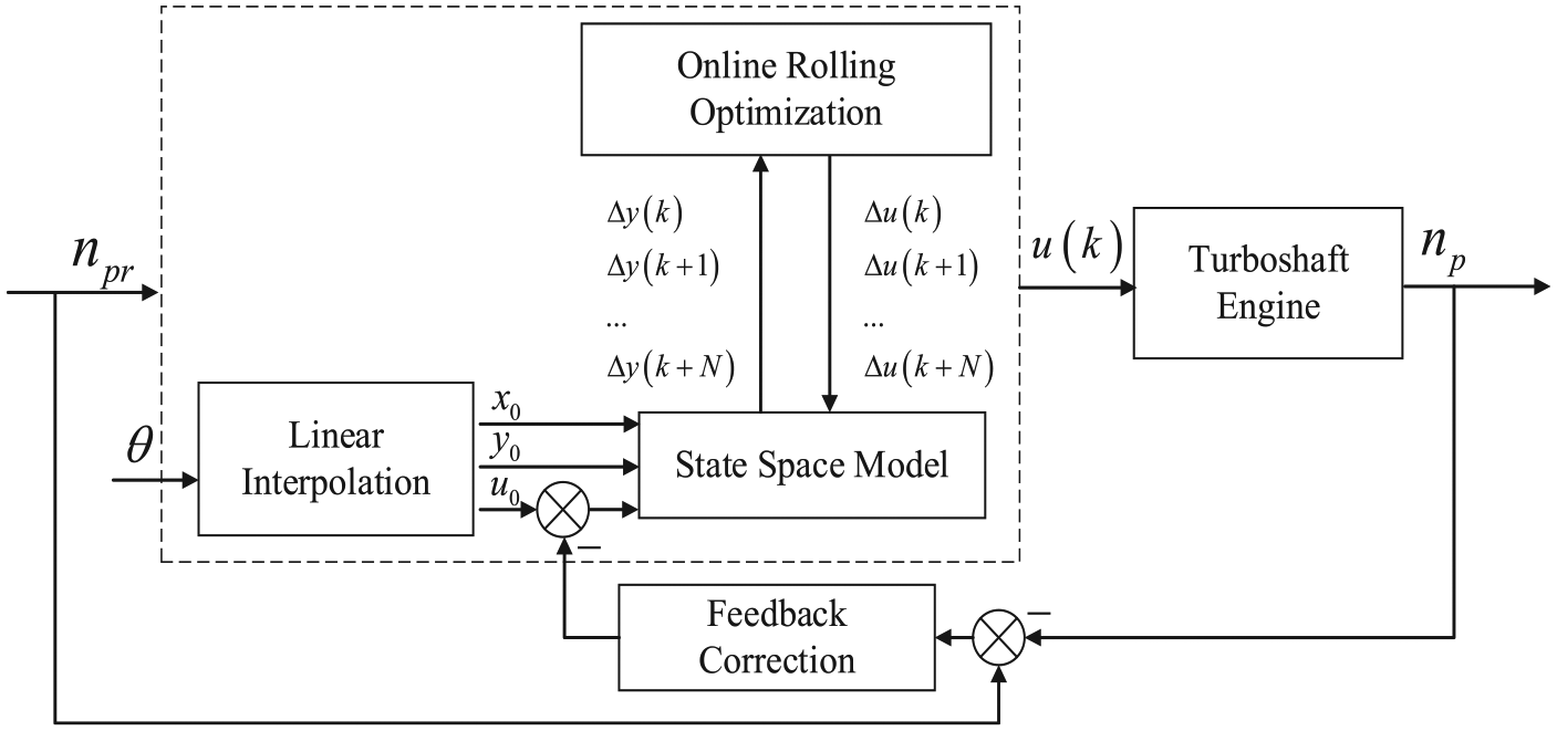
According to the principle of NMPC, the structure of NMPC algorithm is shown in Figure 6. It mainly includes online rolling optimization module, prediction model, feedback correction module, and control object. At time


NMPC algorithmic structure.
The online rolling optimization module iteratively optimizes its output control quantity according to predicted value of the prediction model until optimal control quantity under the constraints is calculated. There is a certain error between any model and real engine. The feedback correction module corrects the command value at time
Prediction model
Nonlinear predictive model is the basis of NMPC. The effectiveness of NMPC is mostly determined by the accuracy and real-time performance of prediction model. A numerical fitting model has been established in section “Simulation model establishment,” but the NMPC controller which uses it as a predictive model has the problem of excessive computation and does not meet the real-time requirements. Therefore, piecewise linearization method is used to establish a micro-turboshaft engine LPV model as the prediction model.18–22 LPV model is simpler and can transform the optimization problem into a standard quadratic programming (QP) problem, which can be solved by QP algorithm without using a computationally intensive sequence quadratic programming (SQP) algorithm, can greatly improve real-time performance of NMPC.23,24
NMPC control target of micro-turboshaft engine is to ensure that the power turbine speed

In the formula,

In the formula,
The state space model is established using the fitting model data of section “Simulation model establishment.” First, a small step instruction is given to control quantity

Establishing a complete LPV model also requires four steady-state point data corresponding to

LPV model structure.
Do the same

Fitting effect of LPV model: (a) fitting effect of core engine speed and (b) fitting effect of power turbine speed.
The LPV model established in this article can obtain steady-state point

According to the relationship between output and state quantity in equation (7), the following formula can be derived

In the formula,

Online optimization module
The NMPC algorithm usually uses the minimum of the quadratic objective function as the optimization target. The main control objective of micro-turboshaft engine is to keep power turbine speed constant. When the speed is disturbed, it needs to be adjusted and stabilized as soon as possible. The quadratic objective function proposed in this article is as follows
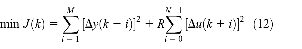
In the formula, the first term

In the formula,
In the formula,

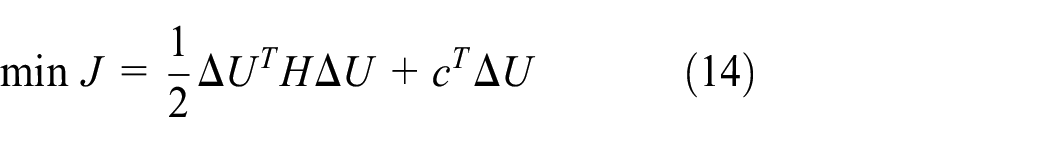
Transform equation (15) to get matrix expression


Combine these matrices to obtain inequality constraints for QP problems. Use QP algorithm to solve the constrained QP problem.
Feedback correction module
NMPC calculates control quantity based on prediction model. The accuracy of model determines the control precision. However, no matter what modeling method is used, it is difficult to avoid the difference between model and real micro-turboshaft engine. In order to enhance robustness and reduce control error, it is necessary to add a feedback correction module in controller.22,25–28
Feedback correction module generally has two ways of correction: one is to modify the prediction model and the other is to modify the control instructions. Since it is difficult to change nonlinear model online, almost all the existing feedback correction modules modify the control instructions, as shown in Figure 6. The LPV prediction model established in this article is a linear model near command speed. If the control instructions are modified, the deviation of the model will be increased. The correction method adopted in this article is shown in Figure 9. The prediction model consists of linear interpolation module and state space module. The feedback correction module can modify the prediction model by modifying linear interpolation output of the LPV model. It first calculates the error of command speed
NMPC algorithm structure based on LPV model.
Algorithm analysis and verification
Simulation analysis
All modules of NMPC algorithm for micro-turboshaft engine have been designed. The simulation experiment is carried out on MATLAB with the numerical steady-state ARX series model established in section “Simulation model establishment” as the control object.
The online optimization module performs the optimal control quantity calculation of NMPC by solving the target optimization function. Different solving algorithms lead to different time consuming, which will have a great impact on the real-time performance of the control system. Therefore, this article first explores the computational speed of different optimization algorithms applied to NMPC. Quadprog (Quadratic Programming) functions of QP algorithm and fmincon (Find Minimum of Constrained Nonlinear Multivariable Function) functions of SQP algorithm in MATLAB are used to calculate the optimal control quantity. A total of 9000 control periods are calculated on a 2.2 GHz computer. While QP algorithm takes 130.356 s, each control period is 14.484 ms, while SQP algorithm takes 423.977 s, each control period is 47.109 ms. It can be seen that QP algorithm is more real-time and meets the requirements of 20 ms control period. SQP algorithm takes a long time and has exceeded 20 ms control period. The control has obvious delay. Therefore, this article chooses QP algorithm as optimization algorithm.
NMPC optimization objective function is shown in equation (12). The equation contains three control parameters: prediction period
The prediction period
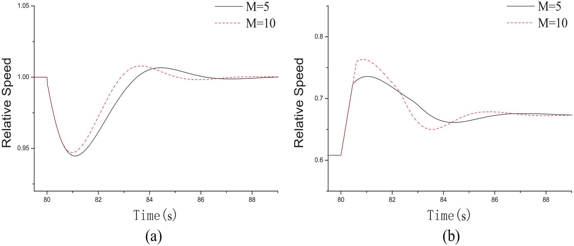
Comparison of NMPC control effects using different
The control period

Comparison of NMPC control effects using different
The second term of optimization objective function represents the degree of change in the control quantity during the prediction period. The larger the coefficient
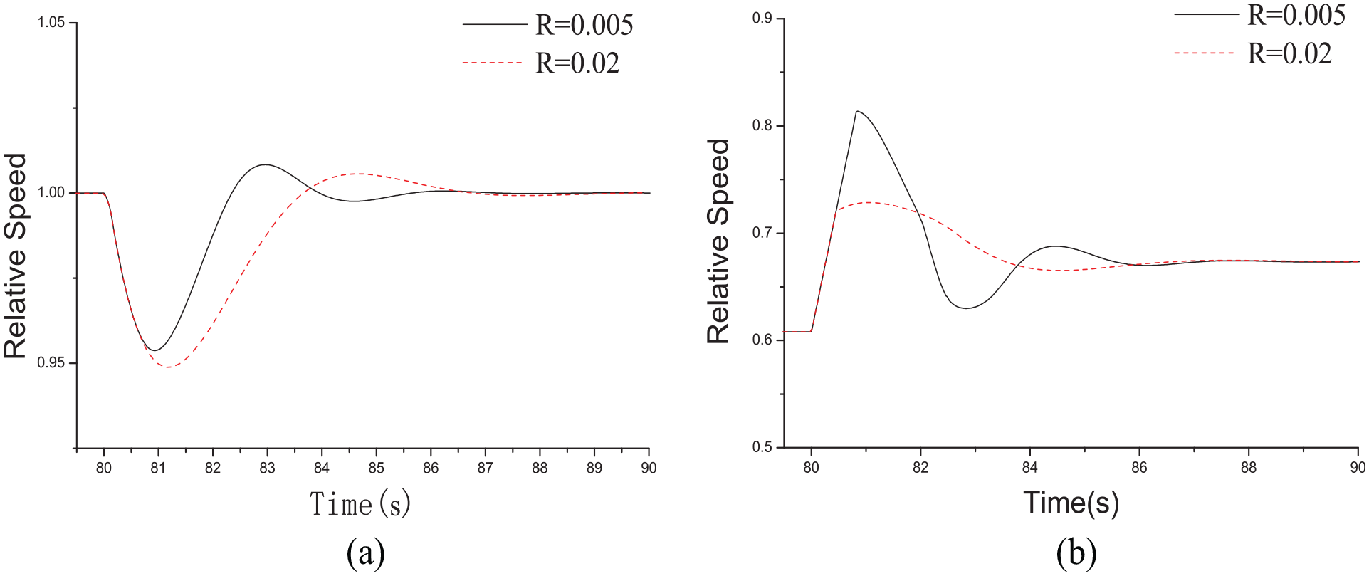
Comparison of NMPC control effects using different
In Figure 12, the speed change of the electric fuel pump at
When

NMPC control effects when
The parameters of the NMPC algorithm are determined by simulation experiments above. Figure 14 shows a comparison of the control effects of NMPC and cascade PI with pitch angle feedforward. The model pitch angle changes as shown in Figure 14(a). Figure 14(b) shows the response of

Simulation comparison between NMPC and cascade PI control: (a) changing curve of pitch angle
Bench test
In order to verify the effectiveness of NMPC algorithm for real micro-turboshaft engines, a bench test verification was carried out on the test bench described in section “Test bench establishment.”
The calculation of NMPC algorithm is large. The numerical simulation in section “Simulation analysis” is performed in a high-performance computer to meet real-time requirements. It is difficult to achieve such high real-time computing tasks in embedded systems with limited resources. Therefore, this article realizes NMPC using host computer to assist calculation. In test experiment, 10,000 periods of control instructions were computed on a 2.2 GHz host computer with a total time of 70 s. The average calculation time is 7 ms, which meets the real-time requirements. In addition, using this solution needs to ensure real-time communication, otherwise, it will cause control delay. The embedded system used in this article uses lightweight IP (lwIP) protocol stack, which is lightweight and efficient. After testing, the communication delay between core controller and host computer is not more than 20 ms, which meets the real-time requirement of communication.
Before the bench experiment, hardware-in-the-loop simulation is required for the reliability and safety of experiment. It is used to verify controller function and control algorithm effects. After verification, the controller has complete monitoring, control, and protection functions. The results of NMPC hardware-in-the-loop simulation are similar to those of the bench tests below, so it is unnecessary to elaborate on them.
The results of the bench test are shown in Figures 15 and 16. The two diagrams are respectively the response comparison of NMPC and cascade PI control with pitch angle feedforward when pitch angle is taking ascend and descent step. Similar to the simulation results, it can be seen that in Figures 15(b) and 16(b), when the pitch angle suddenly changes, NMPC and cascade PI’s electric fuel pump have the same speed response, and both change at the maximum acceleration limit. The overshoot of two control algorithms is basically the same at the beginning, as shown in Figures 15(c) and 16(c). However, the overshoot of NMPC is less than 2% and the cascade PI is about 5% in the follow adjustment process. The smaller overshoot of NMPC also reduces the range of nozzle temperature variation, avoiding over temperature problem during engine control, as shown in Figures 15(d) and 16(d). NMPC has a faster adjustment speed. Its adjustment time is about 3–4 s less than the cascade PI, and its control effect is obviously better than the cascade PI control.

Comparison between NMPC and cascade PI control when

Comparison between NMPC and cascade PI control when
Summary
This article studied the NMPC algorithm of turboshaft engine based on the test bench of micro-turboshaft engine and its numerical fitting model. The structure of NMPC algorithm is designed, and the LPV model near the command speed of engine power turbine is established as the prediction model. The online optimization module is designed to optimize the objective function. The feedback correction module is designed to correct the output of control algorithm. The simulation experiment of NMPC algorithm is carried out on MATLAB, and the control effect is compared with the cascade PI control with pitch angle feedforward. The simulation results show that although NMPC cannot further reduce the maximum overshoot of power turbine speed, it can speed up the adjustment and reduce the speed fluctuation in the adjustment. Its control effect is better than the traditional cascade PI controller.
This article successfully applied the NMPC algorithm to a real micro-turboshaft engine. The results show that compared to cascade PI control with pitch angle feedforward, the NMPC can predict the future response of the engine and achieve stronger control effect. It can overcome the disadvantage of cascade PI which cannot consider the influence of time-delay system, resulting in slow response and large fluctuation of power turbine speed. NMPC has a similar overshoot with PI control when pitch angle suddenly changes. Through the whole control process, NMPC has smaller overall overshoot and faster adjustment speed. It can effectively reduce the temperature change rate before the engine turbine, avoid over temperature and extend engine life.
In this article, NMPC algorithm is calculated on monitoring computer. Some scholars have developed QP algorithm library quadprog++ based on C++ under Linux, which can realize most functions of quadprog function in MATLAB and calculate faster. In the future, NMPC test of complex turboshaft engines and airborne test can be realized through a high-performance embedded system.
Footnotes
Appendix 1
Handling Editor: Jianjun Feng
Declaration of conflicting interests
The author(s) declared no potential conflicts of interest with respect to the research, authorship, and/or publication of this article.
Funding
The author(s) disclosed receipt of the following financial support for the research, authorship, and/or publication of this article: This work was supported by the National Natural Science Foundation of China (No.51976089, No.51576097).