
Abstract
This study aims to model, analyze, and evaluate performance of a flexible manufacturing system, constituting a carousel-based manufacturing and assembly cells layout, configured to produce mixed-model multiple products employing inter-/intra-cellular routing flexibility in which manufacturing and assembly resources are subject to working and failure modes. A hierarchical colored Petri net model is developed to analyze performance of the flexible manufacturing system. Colored Petri net modeling experiments have been conducted to evaluate the system performance for throughput, cycle time, and work-in-process. The system performance has been investigated in relation to material supply and handling system, process execution, and production resources reliability variables. Different input factors are considered for simulation modeling such as mean machining time, mean loading/unloading time, mean assembly time, buffer capacity, material supply inter-arrival time, number of operations between failures, and mean time to repair for production resources; a variation in input factors has shown a significant impact on system performance measures. The colored Petri net–based modeling, simulation, and analysis approach has been demonstrated as an efficient method for carousel-based mixed-model configured flexible manufacturing system.
Keywords
Introduction
Manufacturing generally refers to production processes through which raw material is transformed into a finished product through a defined sequence of operations accomplished by generalized or specialized production resources. Substantial developments have been carried out in manufacturing technologies and processes, but complex relationships among manufacturing system elements are still needed to be explored systematically and thoroughly, 1 to understand dynamics of interrelationship of system elements to estimate or predict the overall performance of the system. Manufacturing is a key element within the overall enterprise, and possible manufacturing outputs depend on strong manufacturing strategy that is considered a powerful communication tool between different levels of management to bring all operations in line with corporate goals. Major themes of manufacturing strategies include custom manufacturing, just-in-time manufacturing, continuous manufacturing, intermittent manufacturing, agile manufacturing, lean manufacturing, and flexible manufacturing. 2 Manufacturing policies, technologies, strategies, and management concepts explore different classification for manufacturing systems. 1 Various types of possible mechanisms are used to classify and describe the features, structure, control, and constraints of the manufacturing systems. 3
Flexible manufacturing systems (FMSs) have been considered suitable to cope up with quick changes in product-mix and volume demands arising in markets. 4 Shortened product life cycle, global market competition, dynamic changes in customer demands, and uncertainty in production systems have necessitated the need of flexibility in manufacturing systems, 5 which is the key factor of an FMS that distinguishes it from other manufacturing systems. Although customization, global competition, and advancement in technology have compelled many industries to look at FMS, the transformation of conventional manufacturing system into FMS is technologically complex and economically expensive task. 6 In order to realize the benefits of an FMS, flexibility characteristics should be embedded in a system that generally adds system complexity that can be mitigated by decomposing a system into modular and/or hierarchical constructs which facilitate evaluation of system flexibility and present better management and economic justification of an FMS. 7 An FMS has capability to coordinate and auto-organize itself with production activities to produce a variety of products, while system flexibility aims to satisfy customer demand. 8 Manufacturing system flexibility has been divided into various categories; machine flexibility refers to a capability of producing a given set of components with ease of set-up change, and routing flexibility typically provide alternate routes to handle breakdowns, avoid disruptions in production runs, and improve resource utilization, 9 whereas product flexibility enables manufacturing systems to respond quickly to the current market fluctuations with growing product variety. 10 An FMS undoubtedly enhances firm’s competitiveness and its position in market. However, the firm may land into trouble and faces some serious issues and various barriers like financial, behavioral, and technical in adoption of FMS. Financial barrier is considered a major barrier and compels many firms to opt partial flexibility instead of complete flexibility at shop floor. 11
The FMS resources can be arranged in various configurations, for example, in-line layout, U-shape layout, rectangular layout, ladder layout, and carousel configured loop layout along with many hybrid schemes. Among different layouts, carousel-based layout offers many advantages like sharing of transport and other material handling resources to rationalize capital investment and have been employed in many high-tech manufacturing environments, for example, automotive, electronic chips, and cell phone manufacturing. Indeed carousel layout has attracted the attention of the research community. Carousel-based layout incorporated with flexible manufacturing and assembly cells has not been investigated in the literature for mixed-model multiple products manufacturing and assembly operations.
This study investigates carousel-based mixed-model multiple products system embedded with flexible manufacturing and assembly cells with inter-/intra-cellular routing flexibility with an objective of analyzing the impact of material supply, material handling and transportation, manufacturing/assembly process execution, and resource reliability factors on system performance measured in terms of cycle time, throughput, and work in progress (WIP).
Related work and contribution
Owing to FMS complex structure, many issues related to FMS design (machine tools, capacity of material handling, size of buffers), planning (allocation of fixture and pallets, assignment of operation), scheduling (optimum machine tool and part sequence), and control (due date requirement and unreliability problems) have been investigated. 12 Whenever an FMS is being planned, the objective is to design an efficient system that can accommodate entire range of parts. This cannot be accomplished until production scheduling, planning, and design stages work well. Analysis and modeling of FMSs play a vital role to address scheduling, planning, and control issues of FMS in addition to performance analysis. 13 Modeling and simulation technique helps to predict and incorporate future changes related to operation, planning, scheduling, and control. 14 FMS modeling and performance analysis are typically preceded before its implementation using mathematical and heuristic algorithm techniques, 15 as system operational and design problems are complex which are usually solved by simulation that is considered as an effective tool for analysis and performance maximization without huge financial investment of FMS physical realization. 16 Generally, production system performance is determined through cycle time, resource utilization, throughput, work-in-process, and related measures. To ensure better performance of any manufacturing system, increase in throughput and resource utilization and decrease in cycle time and WIP are required that can be achieved by minimizing undesirable activities like breakdowns, repair of machines, unavailability of resources and material, tools and products storage etc.
Al-Ahmari and Li 17 analyzed a flexible manufacturing cell composed of multiple machines, a single conveyor, a pallet, and a robot for production rate and resource utilization using stochastic Petri nets (PNs). Capkovic 18 examined throughput of a robotic cell consisting of three machines and conveyer modeled on timed PNs. Peng and Van Brussel 19 designed a scheduler on CPN tool to process multiple products in asynchronous and concurrent ways for an assembly cell of electrical switches. Marin et al. 20 modeled flow shop scheduling process on PN and simulated through tokens and animation in order to calculate makespan. More et al. 21 modeled a case study of FMS consists of two machines, three robots, two conveyors, and an inspection center using PNs. Ali and Murshid 22 applied simulation to analyze the impact of routing flexibility, buffer size, number of parts, and sequencing and dispatching rules on the performance of FMSs under different material handling strategies. Chan 23 studied the impact of routing flexibility on an FMS model consisting of five machines around a closed loop with various levels of routing, and a combination of simulation modeling and Taguchi’s experimental design framework with analysis of variance (ANOVA) is used to find best factor level combination of makespan, lead time, and machine utilization for seven models.
Kucera 24 modeled warehouse product storage mechanism on the CPN tool to estimate operational cost and energy saving of storage system. Da et al. 25 measured system performance in terms of lead time and throughput using time PNs with MATLAB. Saren et al. 26 evaluated total processing time and transition decision using priority rule for a manufacturing cell consisting of two robots, one computer numerical control (CNC) machine, two pallets, a conveyer, and parts storage area through CPN hierarchical modeling and simulation. Saren et al. 27 identified the behavioral structure of a flexible manufacturing cell using hierarchical colored timed PNs modeling and simulation techniques. Hierarchical technique is not always necessary but also helps in demonstration and modeling of complex manufacturing systems. Time in hierarchical model provided more realistic results as compared to normal colored Petri nets (CPNs), while simulation helped to understand the value for real system. Zairi et al. 28 optimized makespan of an FMS model consisting of four machines, two buffers, one automated guided vehicle (AGV), and one conveyor using CPN tool to get optimal schedule. Aized et al. 29 developed a model on CPN to analyze the throughput and cycle time variation of multi-stage, multi-line, and multi-product FMS with planned and unplanned resource break down conditions. Eloundou et al. 30 evaluated three main aspects of routing flexibility: versatility, efficiency, and homogeneous distribution of each elementary path of an FMS and a hierarchical colored Petri nets (HCPN) tools are used to model and simulate an FMS wherein entropy calculations are used to measure the routing flexibility of whole manufacturing system through imbedding decision matrix in simulation model.
Aized 31 applied CPN tools for modeling and simulation of AGV for three different configuration types and observed the impact of guided-path flexibility on cycle time, throughput, and AGV utilization. Lafou et al. 32 proposed a heuristic approach to assess the configuration flexibility and highlighted the main configuration change drivers of an automotive industry mixed-model assembly line. This approach helped designers to compare various mixed-model assembly line configurations and choose the best alternative. The system layout configuration had intense impact on the performance in terms of cost, flexibility, and productivity. Rai and Jayswal 33 highlighted the impact of layouts on performance of a manufacturing system where a loop layout surrounded by seven number of machines with unidirectional material transportation was evaluated by traffic congestion. Chang et al. 34 studied impact of different layouts and material handling system configurations on FMS designing and performance evaluation. A loop layout case study was considered with four machines, and the material handling system was simulated with ProModel and the results of the models examined to quickly respond to part-mix and fluctuated demand patterns. Chae et al. 35 presented a comparison of an open filed layout and closed-loop layout wherein the closed-loop layout was found more efficient. However, efficiency of closed-loop configuration could be improved by changing the rectangular shape into different sizes. Al-Kahtani et al. 36 carried out a simulation-based study or different layouts and material handling system configuration using hypothetical production line of 10-part types for a series of operations, and total production cost, throughput, and total flow time were calculated with variation in speed and number of AGV and cart models.
Yadav and Jayswal 37 addressed minimization of makespan and maximization of machine utilization for an FMS configuration consisted of four jobs on four machines flexible in nature, robot for material handling, AGV for moving the jobs, and automated storage and retrieval system (AS/RS) around a rectangular shaped closed-loop layout. Shivhare and Bansal 38 highlighted loop layout problems associated with the order of stations and cell location, dimension, and orientation around loop.
From the reviewed literature, the performance of different flexible manufacturing cells/systems composed of different configurations layouts is revealed. Layouts and arrangements of resources/machines have intense impact on the performance of manufacturing systems, even minor modifications bring a major change in the performance of manufacturing systems. However, there are many possible changes can be brought in layouts, and impact of those changes can be analyzed through modeling and simulation for different performance matrices. Closed-loop layouts have been analyzed with simple arrangement of resources but not explored yet with complex and scalable approach of cells surrounded by loop layout in the presented literature.
This study presents modeling, simulation, and performance analysis of a carousel-based mixed-model multiple products FMS with manufacturing and assembly resources which are undergoing alternate working and failure modes. Various products adopt different routes on the way of production and assembly in the system to allow un-interpreted finished products supply to accommodate failures of resources, thus ensuring inter-/intra-cellular routing and machine flexibility characteristics of FMS. Carousel-based cellular configuration incorporated with routing, machine, and product flexibility is not evaluated yet with the combination of performance measures like throughput, cycle time, and WIP. Furthermore, manufacturing system dynamics, material flow, time sequence, and process sequence logical relationship are important aspects of this research methodology.
CPN
Evaluative models like static allocation, queuing theory, simulation, and perturbation analysis have long been used for FMS modeling and analysis purposes with restrictive and often theoretical assumptions. However, characteristic behavior of FMS to adapt, react, and preempt to all internal and external disturbances needs to be embedded in modeling paradigms, 39 to model practical environments. PN model can build a network based on the graphical and mathematical formalism to capture parallel, simultaneous, concurrent, asynchronous, conflict and mutual exclusions activities of manufacturing systems and is capable of solving quantitative (throughput, cycle time, resources utilization) and qualitative issues of systems such as deadlock and overflows. 40 CPN is an extension of classical PN with the addition of colors representing distinguishable tokens for modeling large and complex manufacturing systems. Also, CPN gives compact analysis, description, and direct data manipulation of discrete-event dynamical systems (DEDSs), 41 thus it is used for modeling and analysis of FMS in this study. An FMS is a DEDS in which different parts enter, move, and quit at distinct instants of time. PN can capture dynamical behavior and model large systems in a compact format. It is a combination of three nodes; places, transitions, and tokens wherein conditions are described by places and activities are represented by transitions. Tokens are distinguishable in CPN to differentiate various instances of same source. This study involves the definition of CPN is given in Jensen. 42 PN is a bipartite graph represented by a quadruple: PN = (P, T, I, O), where P and T are finite sets of places and transitions, respectively, and I and O are input and output arcs. PN is termed as marked PN if a marking, m, is added and is represented by PN = (P, T, I, O, m). A CPN is a tuple as CPN = (Σ, P, T, A, N, C, G, E, I), where Σ is color sets, P are places, T are transitions, A are arcs, N is a node function, C and G are color and guard functions, and E and I are arc and initialization functions.
FMS configuration
The FMS configuration considered in this study is illustrated in Figure 1 which is composed of five manufacturing and two assembly cells embedded in a carousel-based layout to carry out production and assembly processes for mixed-model multiple product manufacturing system. Mixed-model manufacturing has become a requirement for most of the manufacturing industries nowadays in order to provide greater variety to customers, but it is quite difficult to manufacture mixed-model multiple products with various variants with conventional production/assembly, transportation, material handling, and quality control resources due to complexity arising from diversified requirements of various models of products. With the emergence of state-of-the-art computer-integrated flexible manufacturing and assembly systems, it has now become possible to manufacture mixed-models multiple products employing intelligent algorithms of system control technology. All manufacturing cells have four production resources served by a material handling robot for loading and unloading of materials, whereas each assembly cell has three machines served by an assembly robot.

Configuration of carousel-based flexible manufacturing system.
The system is planned to produce four models, namely, A, B, C, and D with each model having two variants denoted by suffixes 1 and 2, for example, Model A has two variants a1 and a2. All variants follow a specific inter-cellular process sequence, which is shown in following Figure 2. The inter-cellular routing flexibility has been planned in such a way that each variant of a specific model is processed through four out of five manufacturing cells and is subsequently passing through one out of two assembly cells. For example, variant a1 is processed through manufacturing cells (MC1, MC2, MC3, and MC4) and assembly cell AC6, whereas manufacturing cell MC5 and assembly cell AC7 are not required and hence are bypassed.

Inter-cellular parts movement scheme.
Routing flexibility of manufacturing cell
Each manufacturing cell has the same configuration and is equipped with four production machines M1, M2, M3, and M4 and one robot R for material loading/unloading. Routing flexibility is built in each manufacturing cell for continuous production in events of machine failures. Machines M1 and M4 are always in working conditions, whereas machine M2 and M3 can undergo failure conditions after specified interval and can perform operations of each other for continual manufacturing operations. Routing flexibility shows three routes for material flow in Figure 3. Route 1 is a principle course when all four machines are in working conditions. Route 2 is valid only when machine M2 is under failure mode and material will be directed toward M3, which will perform two operations: one for M2 and the second for its own, that is M3, and then material will move on to M4. Route 3 is applicable only when machine M3 is under failure mode and material will flow from M2 to M4 for further machining, whereas M2 will be performing one additional operation that is for M3. Machines undergo failure conditions after a specific number of operations, a condition typically termed as “down” condition and parts will move through alternative routes for processing under such conditions. In case of failures, machines will be repaired and brought back to operation, typically called condition “up” and restart processing of parts.

Routing flexibility of a manufacturing cell.
Routing flexibility of an assembly cell
Each assembly cell is composed of three production machines A1, A2, and A3 and one robot R for loading/unloading of parts. Assembly cells, like manufacturing cells, are also characterized by routing flexibility. The working and routing of assembly cell are given in Figure 4: Route 1 is principle route in which all machines are in “up” condition and are assembling parts. Route 2 is followed by materials when machine A2 is under failure mode and those move toward A3 which performs function of A2 in addition to its own. Route 3 is followed by parts for assembly when A3 is under failure model and A2 performs for both A2 and A3 operations. Figure 4 shows assembly cell routing flexibility.
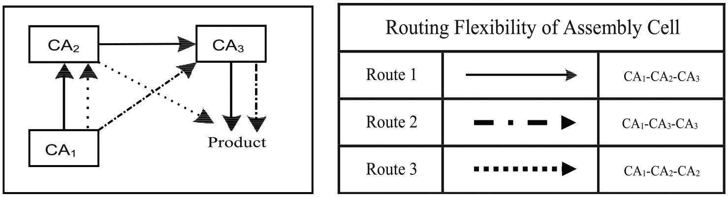
Routing flexibility of an assembly cell.
The above-demonstrated manufacturing and assembly cells configurations employing routing flexibility can produce mixed-model multiple products.
CPN modeling
FMS has been modeled using CPN Tools which is a PN platform based on ML language derived from standard ML general-purpose language. All activities like machining, loading/unloading, transportation, buffer storage, and repair operations have been modeled using exponential distribution functions. The top-down hierarchical modeling approach has been adopted in this study which has the advantage of adding details of any process like manufacturing or assembly and also offers modeling flexibility in terms of adding or deleting any activity or sub-activity during or after model development phases. The model developed for this study is hierarchical as shown in Figure 5 and has three pages: the top level in the hierarchy, called super page, has been used to model overall system and is termed as “FMS” which is also having constructs to control activities like enabling and firing of transitions representing all manufacturing system operations at macro level. The other pages, called subpages, named here as “Manufacturing cells” and “Assembly Cells” are at lower hierarchy level and are connected to super-page “FMS” through hierarchical relationships by port assignment functions. Following Figure 5 shows how super-page is communicating with subpages.

Model hierarchical relationship.
A snapshot of a super-page “FMS” is shown in Figure 6. This super-page is demonstrating a macro-level representation of various system-level phases ranging from material supply to production of finished products. The different raw materials required for mixed model (A, B, C, and D) are loaded on the conveyor in the first phase, move to manufacturing cells which have been placed as a sub-page and after complete manufacturing operations of all five cells, return to super-page from where those are transferred to second sub-page where assembly operations take place in two assembly cells. From assembly operations, materials return to super-page and are delivered as finished products. For the sake of brevity, only super-page of the model developed has been shown in Figure 6.

A snapshot of super-page “FMS” taken from CPN tools.
Modeling assumptions
Following assumption are used in simulation modeling.
The conveyor is continuously moving unidirectional with constant speed.
The conveyor belt conveys parts to the robot which load and unload parts.
Robots are working continuously without any breakdown and repair.
The set-up times are included in machining time.
Production machines are working 8 h/day.
Raw material and demands are always available.
Robot loading/unloading times are the same for all manufacturing and assembly cells.
Results and discussions
FMS performance depends on various input factors which include material supply, material handling and transportation, production/assembly process execution, and resource reliability factors. This study is considering material inter-arrival time (IAT, minutes) and buffer capacity (BC, no. of parts) as material supply variables; conveyor speed (CS, m/min) and robot material loading/unloading time (MLT, min) as material handling factors; mean machining time (MMT, min) and mean assembly time (MAT, min) as process execution factors; and number of operations between failure (NOBF, number) and mean time to repair (MTTR, min) as production resource reliability factors. The impact of these input factors on cycle time (mean number of minutes), mean throughput (mean number of products/month), and WIP (number of products) is examined in this study. All input factors are varied at 10 different levels which are shown in Table 1.
Different levels of input factors.
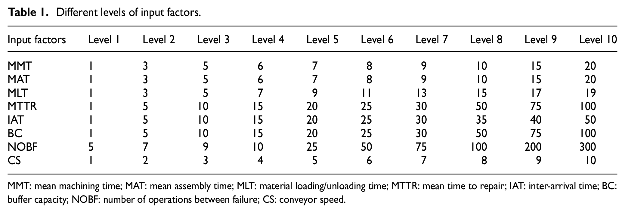
MMT: mean machining time; MAT: mean assembly time; MLT: material loading/unloading time; MTTR: mean time to repair; IAT: inter-arrival time; BC: buffer capacity; NOBF: number of operations between failure; CS: conveyor speed.
Input factors are non-zero, non-negative values taken at 10 various levels in order to explore experiment design space subject to variations in system performance response parameters, and the highest values have been chosen beyond which respective factors show insensitivity to output response parameters which are cycle time, throughput, and WIP. The experiment design space, that is from lowest to highest levels, can be better explored for increasing, decreasing or any other trends with maximum number of increasing input factor levels as compared to typical 5 or 6 levels, hence 10 levels have been investigated. In order to minimize output data variability, all simulation experiments have been replicated 10 times to generate values like average, confidence interval, variance, standard deviation, minimum, and maximum. The simulation results of cycle time are shown in Table 2.
The simulation results of cycle time.

Figure 7 shows the impact of all input factors on the cycle time of products. Material supply input measured as IAT ranges from 1 to 50; its increasing value shows a minor decrease in cycle time because as IAT increases, material supply is delayed. BC is varied from 1 to 100 and is adversely affecting cycle time as there is an increase in cycle time when BC is increased, and BC cannot be taken at too low or high conditions as former can decrease cycle time with accompanying decrease in throughput, whereas later condition increases cycle time but produces high throughput and holds greater WIP. The cycle time increases with an increase in both MMT and MAT as the greater is the process (production or assembly) execution time, the greater is the time required to produce a product. MAT impacts more adversely than MMT, which is due to specific assembly cell configuration adopted. If configurations of both manufacturing and assembly cells are identical and process times for both production and assembly are same (a condition which is impractical to achieve), the impact of both MMT and MAT will be the same. The CS is not affecting cycle time much and is typically held to synchronize material supply to manufacturing and assembly cells in carousal-based FMS. However, material loading and unloading time is much important and has significant impact on cycle time. MLT affects more badly than MMT and MAT because for each production or assembly operation, there is one loading and one unloading operation provided material handling robot never fails. From resource reliability input factors, NOBF for a production resource does not impact much in given experiments because in events of machine failures, materials have been redirected to alternate machine resources to ensure continual supply. However, alternate production resources have to perform dual process under failure conditions until the resource which is under maintenance is up again. Hence, the more is the value of MTTR, the more is the cycle time.

Effect of different input factors on cycle time.
Table 3 shows data for varying all input factors on throughput which is graphically represented in Figure 8. IAT does not affect throughput values unless the material supply is disrupted periodically which can cause a condition known as starvation. An increase in BC value can improve throughput but causes to hold higher WIP which typically increases the cost of production and thus decreases industrial competitiveness. MMT and MAT both adversely impact throughput as with an increase in these input variables, there is an increase in cycle time which decreases corresponding throughput, and the level of adverse impact of both MMT and MAT is due to specific configurations of production and assembly cells adopted in this study. From material handling measures, CS is not affecting throughput much but MLT has a significant impact as for every production and assembly process, there are two MLT operations (loading and unloading) that consume time and increase cycle time and subsequently decrease throughput. From resource reliability factors, NOBF has not much impact as alternate resources are processing in place of principal resources for continual supply, but an increase in MTTR significantly decreases throughput because under longer MTTR value conditions, alternate resources have to process the operations of resources as well which are under repair conditions.
The simulation results of throughput.

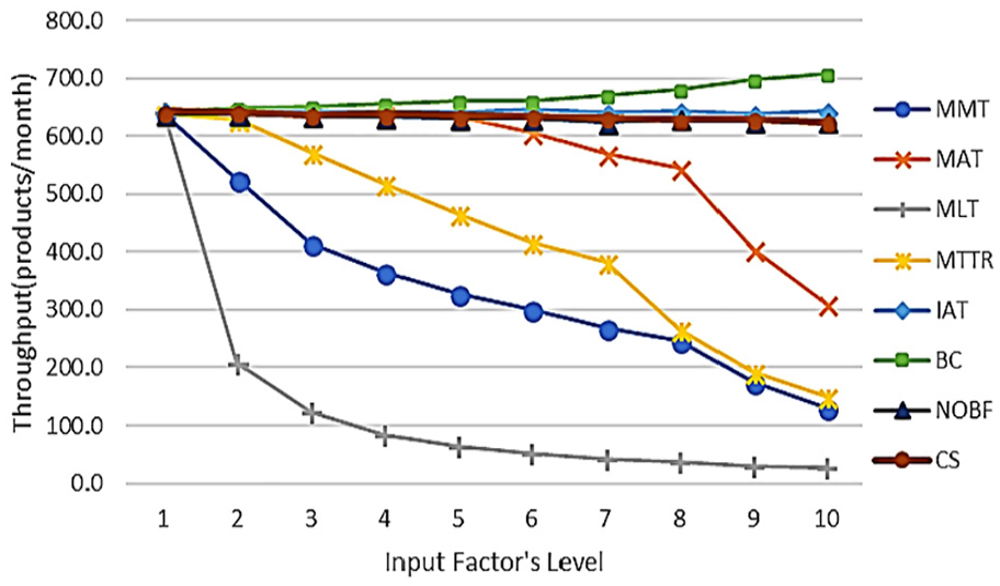
Effect of different input factors on throughput.
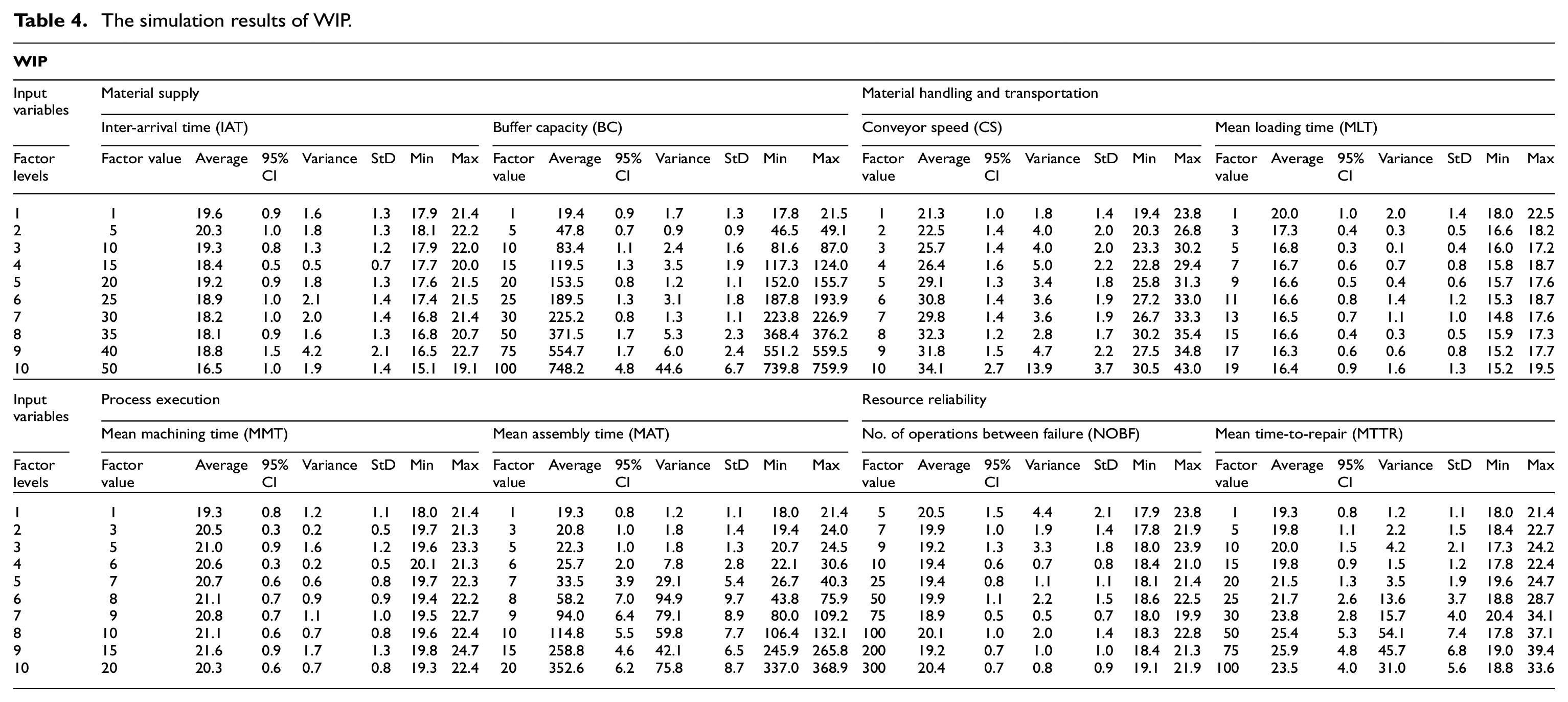
Table 4 and Figure 9 show data for variations of all input variables on WIP. Among input factors studied, BC and MAT are the most significant factors affecting WIP which is increasing as both BC and MAT increase. An increase in WIP means holding more raw and semi-finished materials in the system which causes to increase cost of production per product and thus forces to compromise regarding market competitiveness. MAT is another major input factor that increases WIP because assembly operations are typically placed toward the end of production system and an increase in its value causes to hold more semi-finished materials.
The simulation results of WIP.

Effect of different input factors on WIP.
Conclusions
This study has examined a mixed-model multiple products FMS with routing flexibility and presented an approach for modeling and analysis of carousal-based cellular production systems with a variety of production and assembly resources. PN method has been used to capture DEDS characteristics; specifically, CPN formalism has been employed to develop a compact discrete-event model. Various input parameters belonging to material supply, process execution, material handling, and resource reliability have been studied. However, the rational combination of input significant factors is needed for optimal performance of the addressed system because deployment of FMS involves huge capital investment demands thorough analysis of system design. Designers and system operators deploy such a system in virtual environment before practical implementation on shop floors and gain quick insights into system performance. Moreover, this study may be augmented in future by adding failure mode of material handling robots and comparing carousal-based configuration with ladder layout configuration in which case, material handling continuously moving conveyor can be replaced with AGV system.
Footnotes
Acknowledgements
Authors acknowledge the University of Engineering and Technology Lahore (UET Lahore), Lahore, Pakistan for providing financial support for this study through Notification No. ORIC/101-ASRB/4443 dated 08-11-2017.
Handling Editor: James Baldwin
Declaration of conflicting interests
The author(s) declared no potential conflicts of interest with respect to the research, authorship, and/or publication of this article.
Funding
The author(s) received no financial support for the research, authorship, and/or publication of this article.