
Abstract
Time-varying input delay of actuators, uncertainty of model parameters, and input and output disturbances are important issues in the research on active suspension system of vehicle. In this article, a design methodology involving state observer and observer-based dynamic output-feedback
Keywords
Introduction
Suspension system, which is located between frame and wheels, mainly consists of spring and shock absorber. It has serious influence on the handling stability and the ride comfort of vehicle and is an important part of vehicle chassis. 1 However, the handling stability and the ride comfort are mutually contradictory. Generally speaking, the good handling stability requires the rigid suspension characteristics, while the good ride comfort requires the soft suspension characteristics. At present, there are three main types of vehicle suspension system: passive suspension system (PSS), semi-active suspension system (SASS) and active suspension system (ASS), in which PSS can’t adjust suspension parameters and only be designed in a compromise between the two above performances, and SASS can only adjust the damping of shock absorber according to the driving conditions of vehicle. Compared with PSS and SASS, ASS can automatically adjust the stiffness of spring, the damping of shock absorber, and the height of vehicle body according to the driving conditions of vehicle, and ASS can take into account both of the above properties well synchronously. 2 Therefore, ASS is one of the development directions of vehicle suspension system, and the research on ASS has attracted more and more attention in the recent decades.
ASS is a complex system that integrates machinery,
3
electronics,
4
and hydraulics.
5
Some state variables of ASS are difficult to measure directly, such as acceleration of body vibration, velocity of wheel vibration, and so on, due to the installation location, purchase cost and measurement accuracy of sensors.6,7 This makes the state feedback control of ASS difficult to realize. The static output-feedback control of ASS is simple and feasible, in which the output variables that can be measured directly are used as the feedback signals. However, the measurable output variables can only reflect the local information of ASS, but not the global information of ASS. Nevertheless, the state observer can reconstruct the state variables of ASS according to the variables which can be measured directly (such as input variables, output variables, etc.), and the reconstructed state variables may be equivalent to the original state variables under the certain indicators.
8
Hence, the observer-based control of ASS is one of the focuses of ASS research. A dynamic output-feedback
Recently, time-varying input delay of actuators, 22 uncertainty of model parameters,23,24 and input and output disturbances are important issues in the research on the ASS of vehicle. They are interrelated and have important influence on the performances of ASS. However, few of the existing related references involve the above four factors simultaneously, especially the design methodology involving state observer and observer-based controller considering the above four factors simultaneously for ASS based on quarter-vehicle model. The two contributions of this study are summarized simply as follows:
Based on the Lyapunov–Krasovskii functional and LMIs,
25
a design methodology involving state observer and observer-based dynamic output-feedback
The observer gain matrix and the controller gain matrix are obtained by means of the designed observer-based controller and the technical parameters of selected vehicle; the MATLAB/Simulink model of this system is established; and the numerical simulations of three typical cases are provided to validate the feasibility of the given scheme.
The following sections are arranged as follows. In the “Problem formulation” section, the dynamics equations of ASS with time-varying delay are established according to its structure and principle, and its state equations, state observer, and observer-based controller considering time-varying delay, uncertainty of model parameters, and input and output disturbances are given separately. In the “Main results” section, the observer-based dynamic output-feedback
Problem formulation
Based on the two degrees of freedom and the quarter-vehicle model, the simplified model of ASS with actuator delay is expressed as Figure 1, where

Simplified model of quarter-vehicle ASS.
In the light of the Newton’s second law and Figure 1, the dynamics equations of ASS based on quarter-vehicle model are obtained as 26

in which

where both
Based on the actual working characteristics and expectations of ASS, the relative displacement of vehicle body
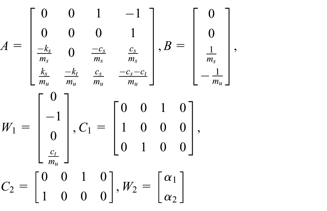
According to equation (1), in consideration of the time-varying delay of actuators, the uncertainty of model parameters, and the input and output disturbances at the same time, the state-space equations of ASS based on quarter-vehicle model may be obtained as follows

in which
in which both
Suppose both of

in which
According to the state-space equations of quarter-vehicle ASS (equation (3)), the state observer and the observer-based controller of ASS may be expressed as below

and

in which
Main results
The state observer and the observer-based controller considering the above four factors simultaneously will be constructed for ASS based on quarter-vehicle model using the Lyapunov–Krasovskii functional and LMIs in this section, and the design of observer-based controller will be converted into the solving problem of LMIs.
Theorem 1
For the quarter-vehicle ASS (equation (3)), if there are symmetric positive-definite matrices


where “★” denotes the matrix obtained by matrix symmetry, and

then the quarter-vehicle ASS (equation (3)) with the state observer (equation (5)) and the observer-based controller (equation (6)) where

is asymptotically stable. ■
Proof
Let the error of state observer
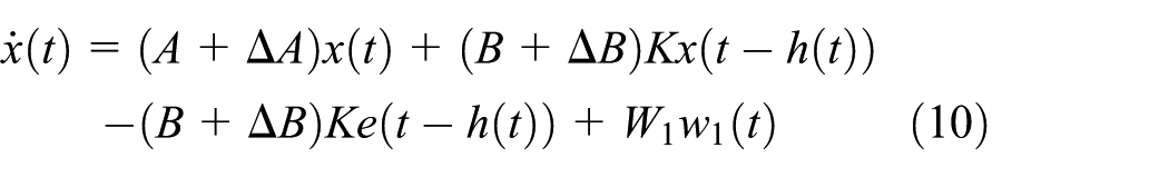

From equations (10) and (11),

From equations (10) and (12), the augmented system may be given as follows

Introduce the Lyapunov–Krasovskii functional as below

in which
From equations (2) and (14),

Assuming that there are no input and output disturbances, that is

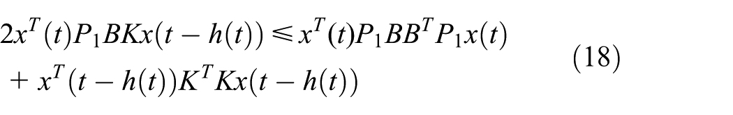
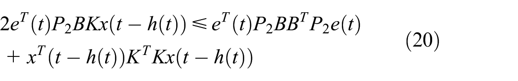
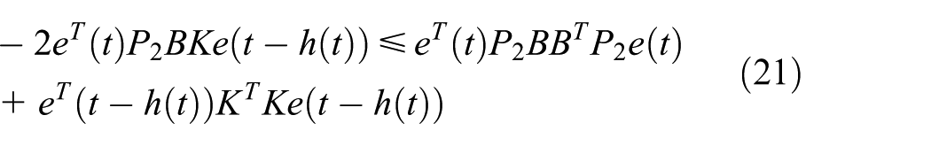
From Lemma 1 in Appendix 1, we are able to get the following inequalities


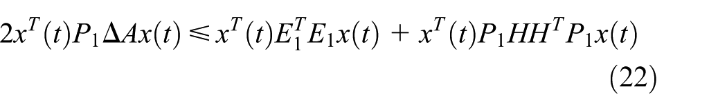
From equation (4) and Lemma 2 in Appendix 1, we are able to get the inequalities as below


From equations (17)–(27), equation (16) may be shown as below

where
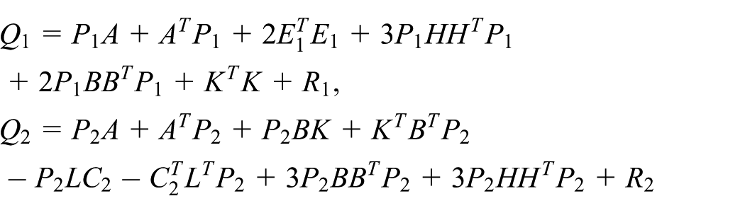
In order to simplify equation (28), we set

Simultaneously,


For the active suspension system (equation (3)),

Considering

where

Obviously,

From equations (3), (13), (15), and (29), equation (34) may be shown as below

From Lemma 1 in Appendix 1, we are able to get the following inequalities
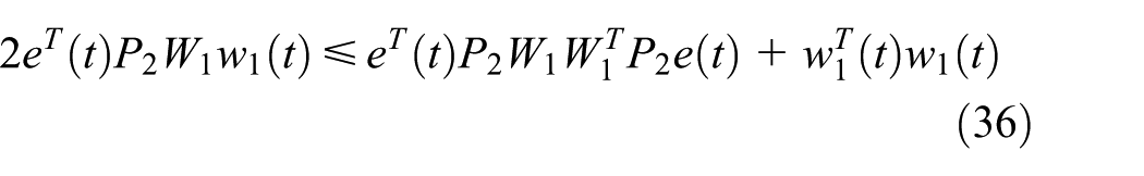
According to equations (36) and (37), equation (35) can be converted to

where

According to equation (30) and the Schur complement theorem (Lemma 3 in Appendix 1),

where
From equation (9), equation (31), and the Schur complement theorem (Lemma 3 in Appendix 1),

where

From equations (7) and (8), it’s easy to find
It is obvious from equation (38):

Hence, the quarter-vehicle ASS (equation (3)) with the proposed observer (equation (5)) and the developed controller (equation (6)), where
Numerical simulation
The simulation results of several numerical cases are given to verify the correctness and practicability of the proposed scheme. The related parameters of ASS model are listed as follows:

Block diagram of quarter-vehicle ASS.
The numerical simulation model of the ASS mentioned above based on a quarter-vehicle model is set up as Figure 3, based on MATLAB/Simulink software.

Numerical simulation model of dynamic output-feedback
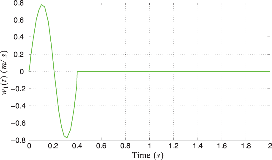
In view of equation (2), the input delay of ASS actuator is set as

Time-varying input delay of actuators: (a) signal curve of
On the basis of the LMIs (equations (7) and (8)), K and L may be obtained as follows

In accordance with equation (4), the time-varying matrices of uncertainty parameters with norm-bounded are respectively taken as follows
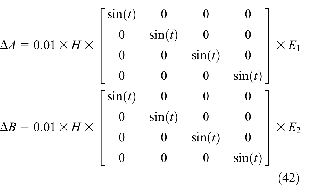
in which
Numerical simulation without disturbances
Without regard for disturbances, the original values of system state vector and the simulation time are taken as

Signal curves of main performance parameters: (a) acceleration of vehicle body vibration, (b) velocity of vehicle body vibration, (c) relative displacement of vehicle body, and (d) relative displacement of vehicle wheel.

Signal curve of control input with a time-varying delay.
As shown in Figure 5, the acceleration of vehicle body vibration, the velocity of vehicle body vibration, the relative displacement of vehicle body, and the relative displacement of vehicle wheel of ASS with actuator delay and uncertainty of model parameters are convergent and asymptotically stable, and the required suspension performances can be satisfied by the designed observer-based controller. Meanwhile, as shown in Figure 6, the actuator delay of ASS is about 0.5 s, the maximum input force of this system is about 60 N, the input force tends to zero after 8 s, and the change curve of input signal can meet the system demands.
Numerical simulation with input disturbance
An isolated bump is used to demonstrate the response performances of the ASS with the proposed observer-based controller under the input disturbance caused by uneven pavement. The isolated bump is taken into account as follows 10

in which L and H express the length and height of the isolated bump respectively and v is the vehicle speed. Assume
Input disturbance of uneven road surface.
Without regard for output disturbance caused by sensor measurement in Figure 3, the original values of system state vector and the simulation time are taken as
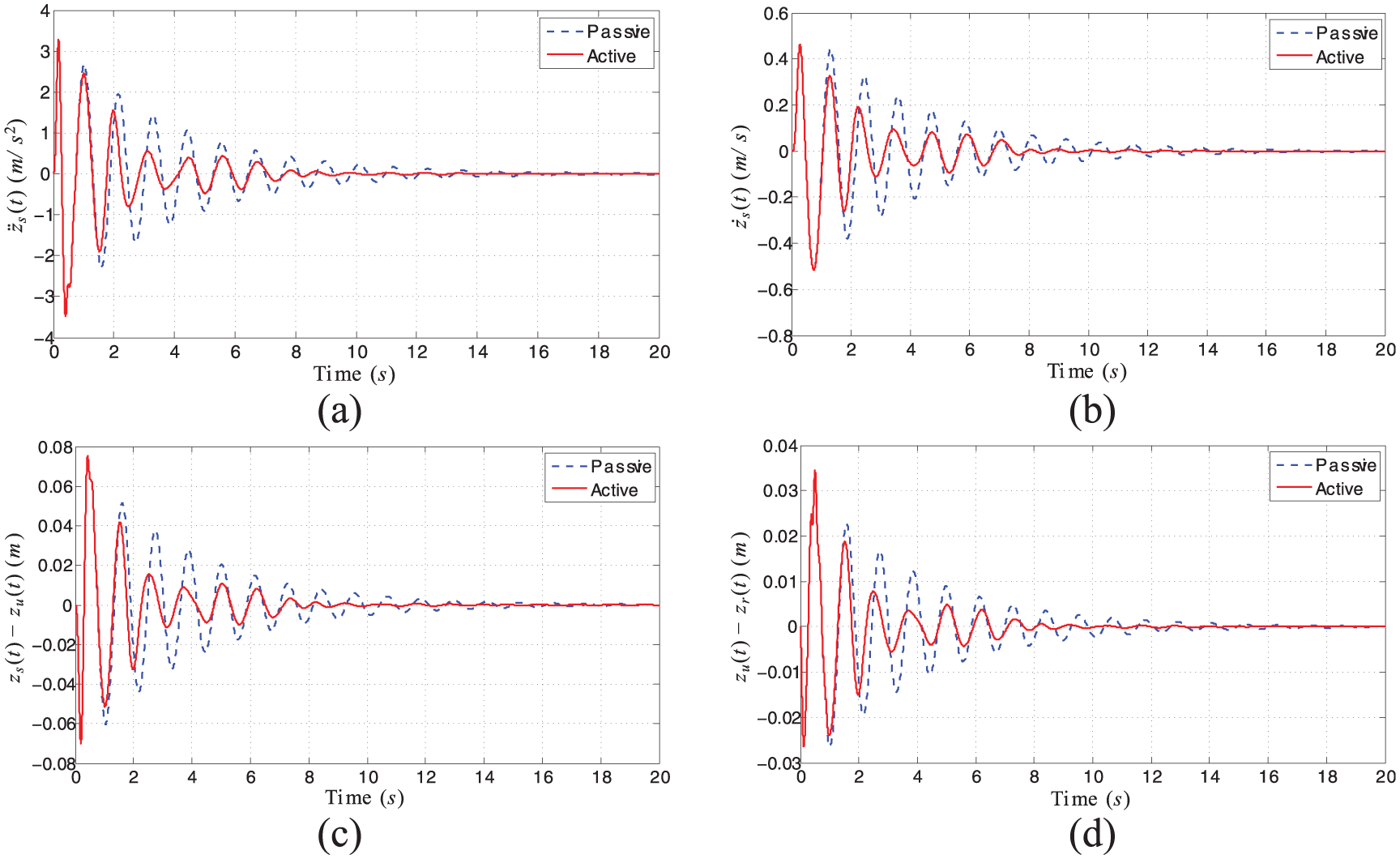
Comparison curves of main performance parameters: (a) acceleration of vehicle body vibration, (b) velocity of vehicle body vibration, (c) relative displacement of vehicle body, and (d) relative displacement of vehicle wheel.

Signal curve of system control input for an isolated bump.
As shown in Figure 8, it’s easy to see that the attenuation speeds of the acceleration of vehicle body vibration, the velocity of vehicle body vibration, the relative displacement of vehicle body, and the relative displacement of vehicle wheel of ASS are all rapid relative to PSS. This indicates that the ASS using the proposed observer-based controller has better responsiveness to the input disturbance caused by the uneven road, and the better suspension performances can be satisfied by the designed observer-based controller. Meanwhile, it’s easy to see from Figure 9 that the input delay of actuator is about 0.5 s, the maximum input force of this system is about 100 N, the input force tends to zero after 10 s, and the change curve of input signal can meet the system demands.
Numerical simulation with input and output disturbances
The input and output disturbances of this system are taken into account simultaneously. The input disturbance curve of uneven road surface is also shown in Figure 7; the output disturbance caused by sensor measurement is set as

Output disturbance curves of sensor measurement.
Through numerical simulation, the comparison curves of acceleration of vehicle body vibration, velocity of vehicle body vibration, relative displacement of vehicle body, and relative displacement of vehicle wheel between the ASS only with input disturbance caused by the uneven road and the ASS with both input disturbance caused by the uneven road and the output disturbance caused by sensor measurement are shown as Figure 11, and the comparison curves of system control input with a time-varying delay are shown as Figure 12.
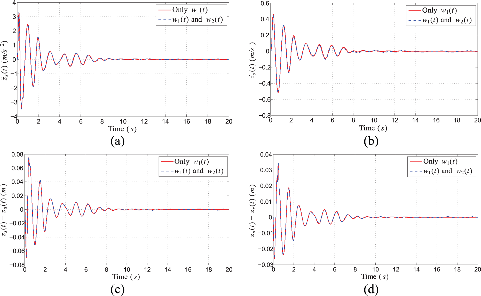
Comparison curves of suspension performance parameters: (a) acceleration of vehicle body vibration, (b) velocity of vehicle body vibration, (c) relative displacement of vehicle body, and (d) relative displacement of vehicle wheel.

Comparison curves of system control inputs.
As shown in Figure 11, it’s easy to see that the two comparison curves of acceleration of vehicle body vibration, velocity of vehicle body vibration, relative displacement of vehicle body, and relative displacement of vehicle wheel respectively are almost identical. Meanwhile, it can be seen from Figure 12 that the two comparison curves of system control inputs are roughly consistent. Both of them have an actuator input delay of about 0.5 s, and both the maximum input forces of them are about 100 N. The input force of the ASS only with the input disturbance caused by the uneven road tends to zero after 10 s; nevertheless, the input force of the ASS with both the input disturbance caused by the uneven road and the output disturbance caused by sensor measurement is still slightly adjusted according to the input and output disturbances after 10 s. These indicate that the developed observer-based controller for ASS can solve the problems caused by the output disturbance of sensor measurement well.
Conclusion
This article proposed a design methodology of observer-based
Footnotes
Appendix 1
Handling Editor: António Mendes Lopes
Declaration of conflicting interests
The author(s) declared no potential conflicts of interest with respect to the research, authorship, and/or publication of this article.
Funding
The author(s) disclosed receipt of the following financial support for the research, authorship, and/or publication of this article: This work was jointly supported by the National Natural Science Foundation of China (Grants 11705122, 51705221, 51875258, and 61902268); Overseas Training Program for Universities of Jiangsu Province; Department of Building and Real Estate of the Hong Kong Polytechnic University; General Research Fund titled “Proactive Monitoring of Work-Related MSD Risk Factors and Fall Risks of Construction Workers Using Wearable Insoles” under Grant BRE/PolyU 152099/18E; General Research Fund titled “In Search of a Suitable Tool for Proactive Physical Fatigue Assessment: An Invasive to Non-Invasive Approach” under Grant PolyU 15204719/18E; Natural Science Foundation of the Hong Kong Polytechnic University (Grant G-YW3X); Research Foundation of Department of Education of Sichuan Province under Grants 17ZA0271 and 18ZA0357; Sichuan Science and Technology Program of China under Grants 19ZDZX0037, 2019YFSY0045, 2018 JY0197, and 2016SZ0074; Sichuan Key Provincial Research Base of Intelligent Tourism under Grant ZHZJ18-01; Open Foundation of Artificial Intelligence Key Laboratory of Sichuan Province under Grants 2018RZJ01 and 2017RZJ02; and Natural Science Foundation of Sichuan University of Science and Engineering under Grants 2017RCL52, 2018 RCL18, and 2017RCL12, and Zigong Science and Technology Program of China under Grants 2019YYJC03, and 2019YYJC15).