
Abstract
The active suspension systems have attracted increasing attentions because of its advantages in improving automotive dynamic performance. This paper focuses on the fuzzy robust non-fragile
Introduction
The suspension system is one of the significant parts of the cars.
1
It is composed of shock absorbers, connecting rods and springs. Its main function is to transmit the forces and moments between the wheels and the vehicle body, which has a great effect on improving the vehicle performance.
2
Due to the importance of the suspension system, many researches have been carried out. Nowadays, the semi-active suspension system
3
and the active suspension system (ASS)4,5 are widely used in modern vehicles. Further, the semi-active suspension and the ASS adopt different approaches to promote the ride comfort and the handing stability. However, the ride comfort, vehicle stability and road holding are in contradiction.
6
Therefore, how to design a suspension system so that these performances can reach an optimal state is greatly significant. Considering the above problems, the ASS that combines the excellent control algorithms is a good choice. It has become the research focus of scholars.7,8 As a result, numerous control methods have been applied to the system to improve the comprehensive suspension performance, such as model predictive control,9,10 sliding model control,11–13 adaptive control,14–16 fault tolerant control,
17
and robust control.18–22 In particular, the robust control, such as
Due to the transmission of information between control devices and the actuators, the situation of time delay will inevitably exist in the ASS. 23 In addition, the time delay is always changing owing to the changes in the environment. It is particularly important to note that the existence of time delay will deteriorate the control effect of the controller and even make the ASS unstable.24,25 Therefore, this phenomenon must be taken into consideration. In Du et al. 26 and Karim Afshar, 27 the controllers were proposed to tackle the constant delay in the actuators. In Gao et al. 28 and Li et al., 29 by transforming the sampling moment into the form of continuous time delay, a sampled-data H∞ controller was proposed. In Li et al.,30,31 the Lyapunov–Krasovskii functions were designed to cope with the actuators time delay questions. Therefore, the time delay problem deserves more researchers’ attention.
In reality, owing to the aging of actuators and other situations, the actuators usually appear control disturbance phenomenon. If uncertainties occur in the process of the system, these situations will seriously affect the control performance, making the suspension performance worse. Therefore, it is necessary to consider the uncertainties of the actuators. In recent years, linear fractional transformation (LFT) has been widely used to solve such problems.32,33 Moreover, the ASS is a highly nonlinear system, such as the nonlinearity between damping and stiffness. In the recent studies, the Takagi-Sugeno (T-S) fuzzy approach has been extensively applied to settle the nonlinear characteristics of the ASS. Through a series of constructed linear subsystems, the original system is represented by weighting method, which can be easily solved by the linear system theory. In Li et al.20,29,31 and Xu et al., 33 taken the sprung mass and the un-sprung mass changing within a certain range into consideration, the T-S fuzzy model was established to deal with the parameter uncertainties of the suspension systems. In Zhang et al., 34 based on the T-S fuzzy model, a novel fuzzy controller was proposed for the ASS subject to the sensor failure while the constrained stated were ensured simultaneously.
Through the above discussion, a fuzzy non-fragile
A T-S fuzzy model is established to describe the high nonlinearity of the spring force and the damping force of ASS in the framework of
A parameter Lyapunov function is designed to acquire less conservative sufficient conditions to satisfy both the stability and constraints of the closed-loop system.
A co-design criterion is proposed for the concerned nonlinear suspension system with the input time delay and control uncertainties.
The remaining of the article is organized as below. Section 2 shows the T-S fuzzy model and the constrained performance. Section 3 shows the design of the proposed controller. Section 4 presents the simulation and experiment results. Finally, conclusions of the paper are presented in Section 5.
Problem formulation
Description of an ASS model
In this part, the suspension model is given in Figure 1. Assuming that the wheel has no lift and no slip, according to the second theorem of Newton’s classical mechanics, the ideal dynamics equations can be obtained as follows:
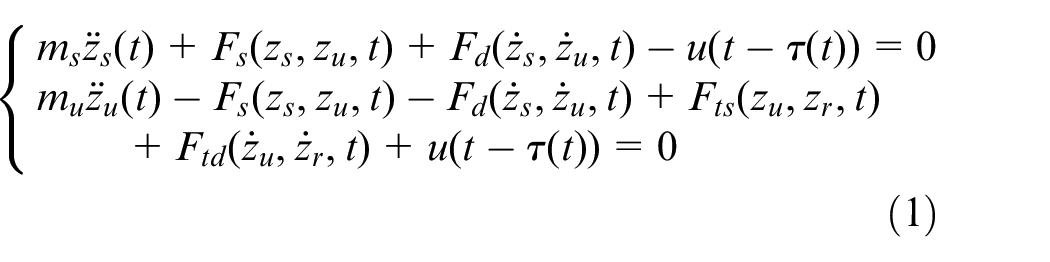
where ms is the sprung mass; mu is the un-sprung mass; Fd and Fs are the spring and damper forces, respectively; Fts and Ftd are tire force and damping force; zu and zs indicate the vertical displacement of the un-sprung mass and the sprung mass; zr is the irregular road surface incentives; u represents the actuator force. Further, τ(t) represents the time varying delay of the actuator, which satisfies
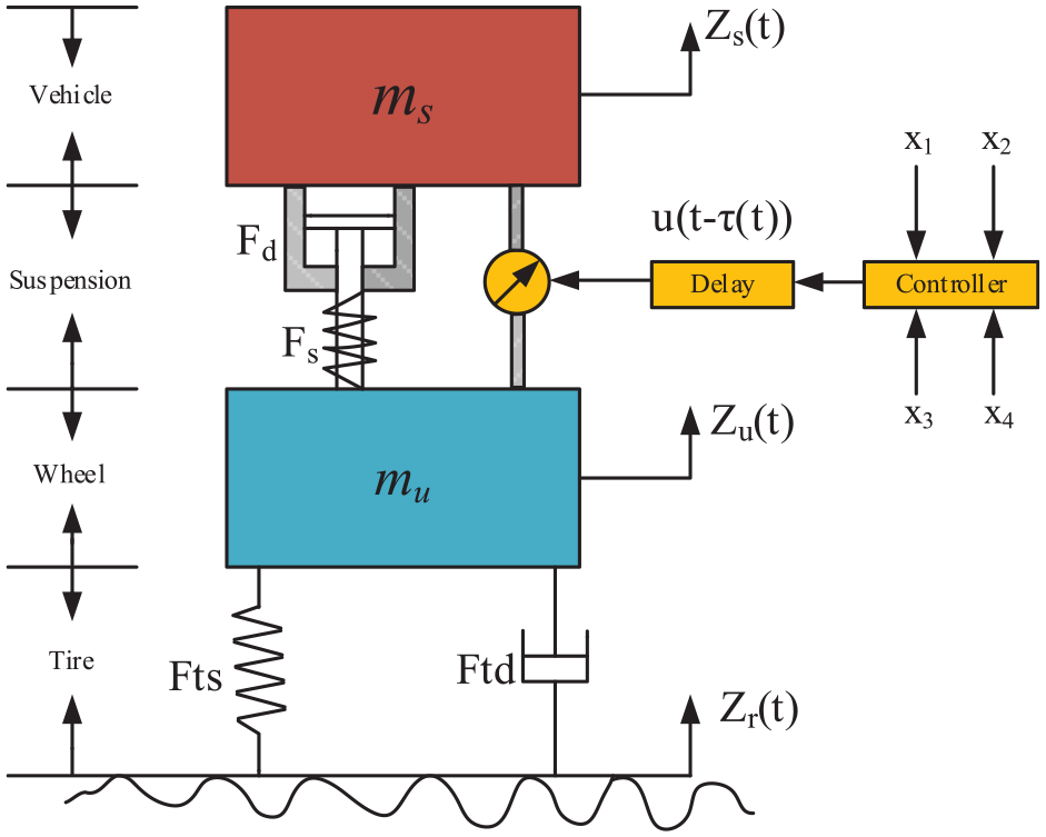
Two-degree-of-freedom automobile active suspension model.
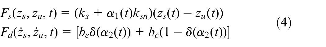
In the above formula, the mechanical properties of the suspension system and tires have the following forms:
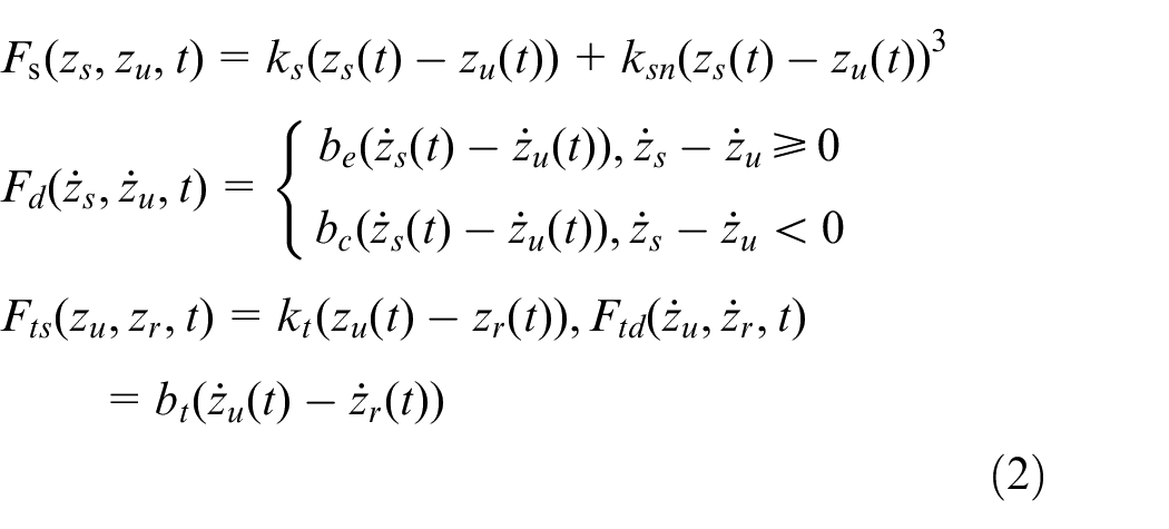
where ks is the spring stiffness coefficient of the linear part and ksn is the stiffness coefficient of the cubic part; be and bc are the tension and compression damping coefficient; kt and bt are the tire stiffness and damping coefficients.
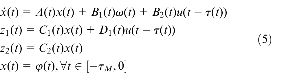
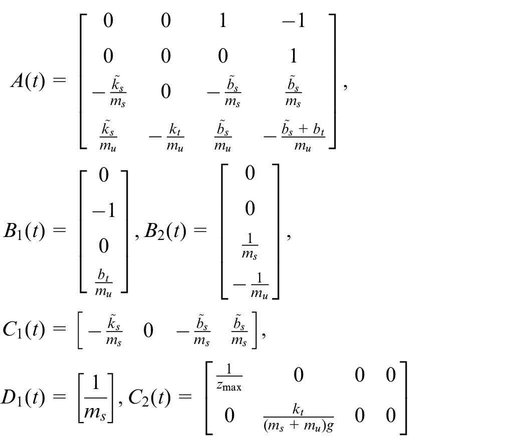
Considering the convenience and availability of the state space equation, by setting the following state variable vectors and control outputs as:
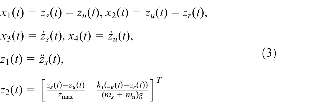
where
T-S fuzzy ASS modeling
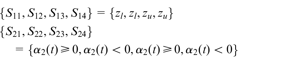
According to the ASS model established in Section 2.1, the travel of the suspension varies within a certain range. When
Then, by defining two antecedent variables
In the above formula,
where
where
Therefore, the nonlinear ASS can be represented using the T-S fuzzy method.


According to the above fuzzy rules,
The whole T-S model can be presented as:
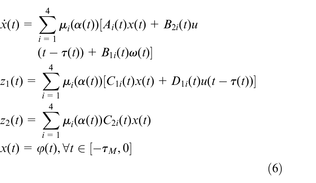
where the membership function can be shown as follows:
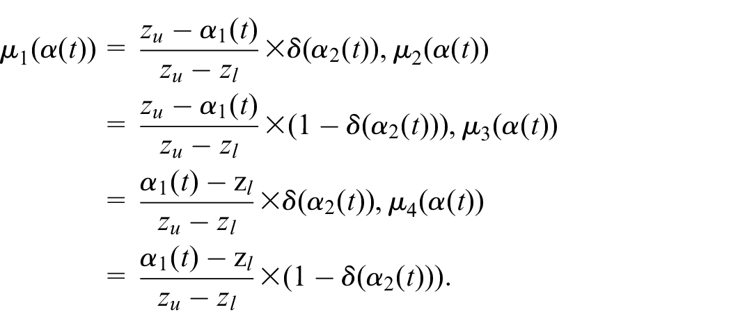
The fuzzy weighting functions satisfies
Fuzzy robust H∞ controller
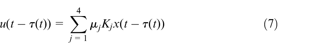
Through the parallel distributed compensation (PDC) method, the following fuzzy robust H∞ controller is given as below:

The whole fuzzy controller can be presented as follows:
Then, the robust non-fragile controller can be described as
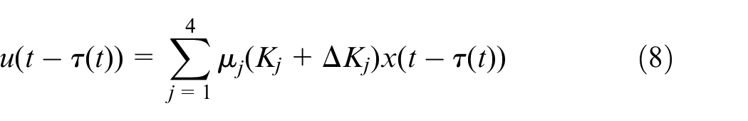

where Kj (j =1,2,3,4) denotes the controller gain matrices.
Finally, based on (6), (8), and (9), the nonlinear ASS can be obtained as follows:
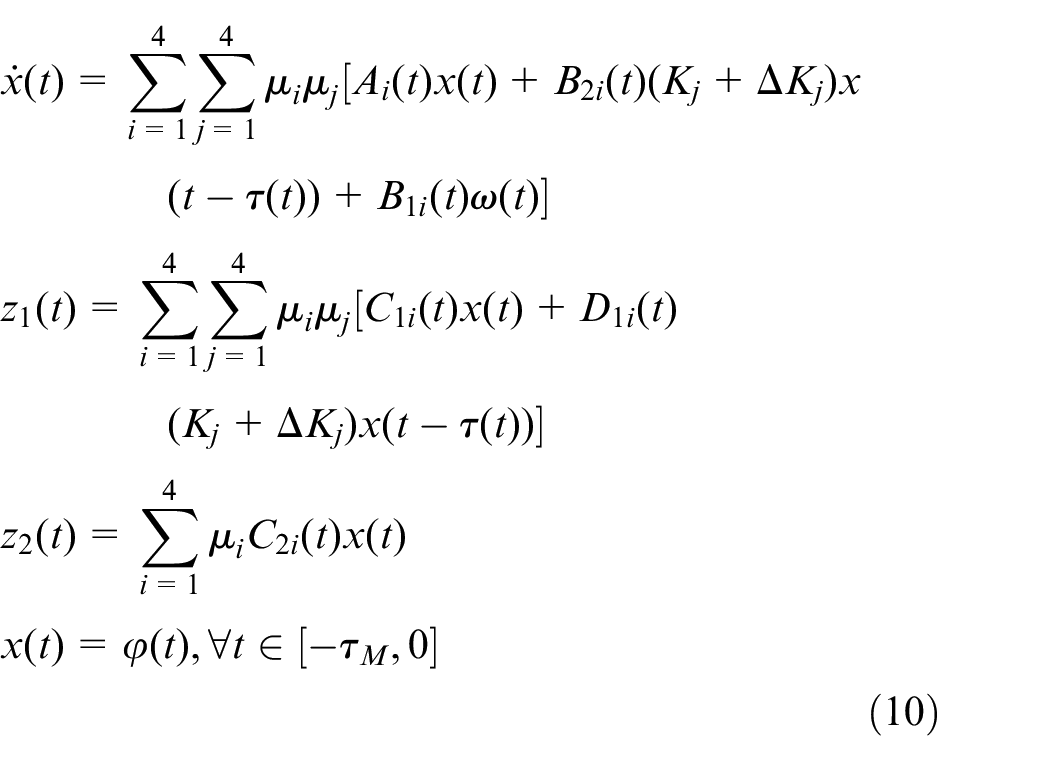
Control objectives
Road holding, ride comfort and handling stability are important for the vehicle. The following targets are the control objectives:
Ride comfort: the control goal is to obtain the minimum value of

Handling stability: the suspension disturbance cannot exceed its limit value. That is

Road holding: to make the vehicle wheel keep in contact with the road, the dynamic load is needed to be less than the static load. That is

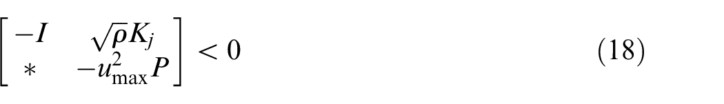
Actuator limitation: due to the limitation of engine power, the output of the actuator is saturated. Therefore, the output force must be limited. That is

Through the above analysis, a generalized

Main results
Stability analysis and
performance constraints
This section presents a sufficient criterion for the proposed controller. The criterion can effectively keep the closed-loop system in (11) asymptotic stability. The constrained states are satisfied at the same time.
The lemmas applied in the following proof process are given in the Appendix A.

Design of fuzzy controller
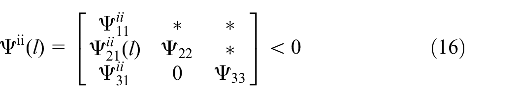
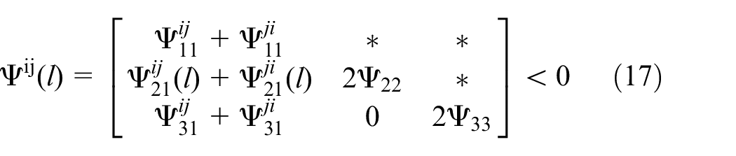
In this part, a sufficient condition is introduced to calculate the local feedback gain


Design of fuzzy non-fragile controller
In this part, taken the control uncertainty into account, the following theorem is introduced to further proposed the fuzzy non-fragile controller.

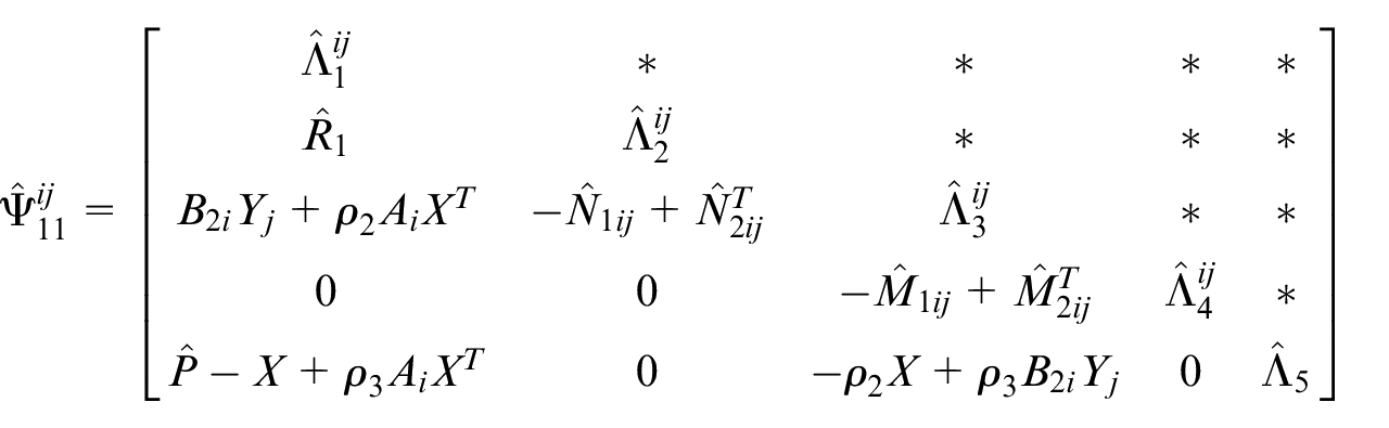
where
Similarly, the proof process is similar to the Theorem 2, which is neglected here. Therefore, the proof process is finished.
Numerical simulations
In this section, numerical simulation and suspension plant experiments are carried out to verify the effectiveness of the robust nonfragile
Simulation results
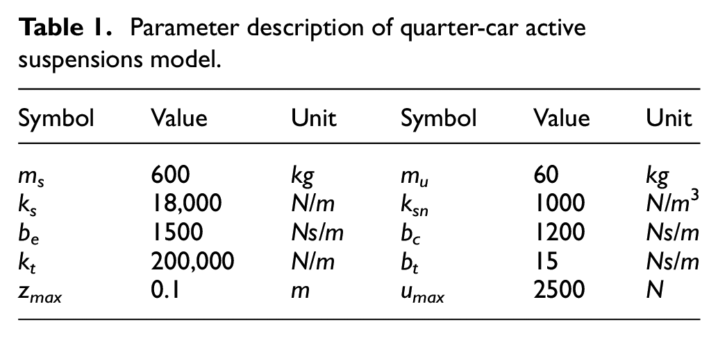
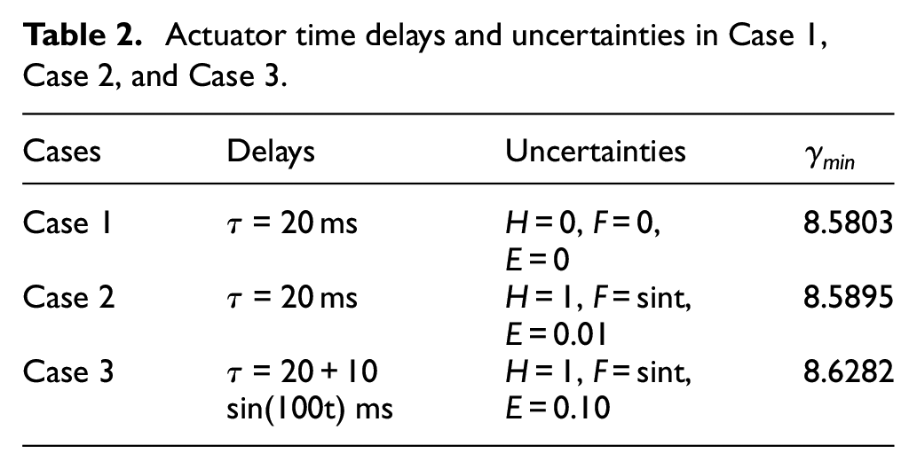
The suspension parameters are presented in Table 1. Three different cases are listed in Table 2 to verify the proposed controller performance. Then, the corresponding control laws can be calculated by Theorem 2 and 3. In Li et al.,
29
with the input delay approach, the active suspension system controller was constructed as a continuous control signal based on a discrete signal with an input time delay. To demonstrate the superiorities of the proposed control algorithm, the fuzzy sampled-data
Parameter description of quarter-car active suspensions model.
Actuator time delays and uncertainties in Case 1, Case 2, and Case 3.
A bump profile is used to demonstrate the effectiveness of the proposed controller, which can be described as follows:
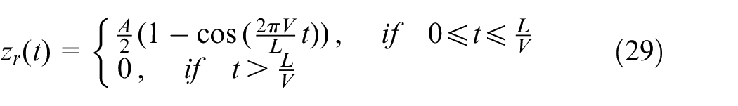
where L = 5m represents the bump’s length, A = 60mm represent the bump’s height, and V = 35 km/h represents the forward speed of the car.
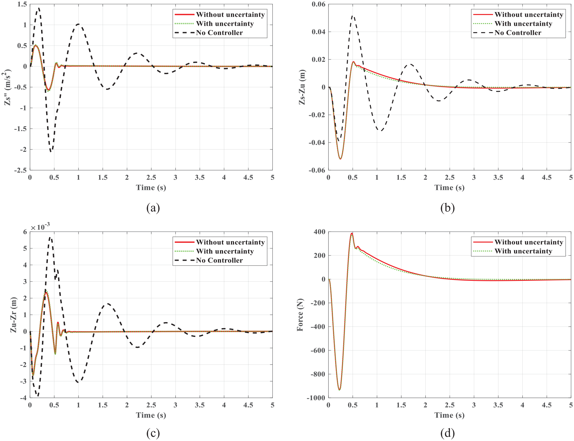
Figures 2 and 3 show the case of Case 1 and Case 2 during the bump response of the ASS, respectively. In Figure 2, the red line, the blue line and the black line denote the proposed controller, the compared controller and the passive suspension system. In Figure 2, to better highlight the characteristics of sampled-data control, the plots of Figure 2(a) and (d) are partially enlarged. It can be clearly observed the performance of sampled-data control and the sampling time is selected as 0.01 s. The proposed controller can yield a less sprung mass acceleration compared with the other two controllers and satisfy the constraint indexes of the suspension. It means that the proposed controller is superior than the compared controller and the passive system in improving ride comfort. In Figure 3, despite the uncertainty of the actuator, the ASS can still keep in a good performance compared with the actuator in normal condition in almost all respects. It denotes that even there is some uncertainty in the actuator, the proposed controller can make the suspension system stable and maintain an excellent performance of the system. Those simulation experiments demonstrate the effectiveness and robustness of the proposed controller.
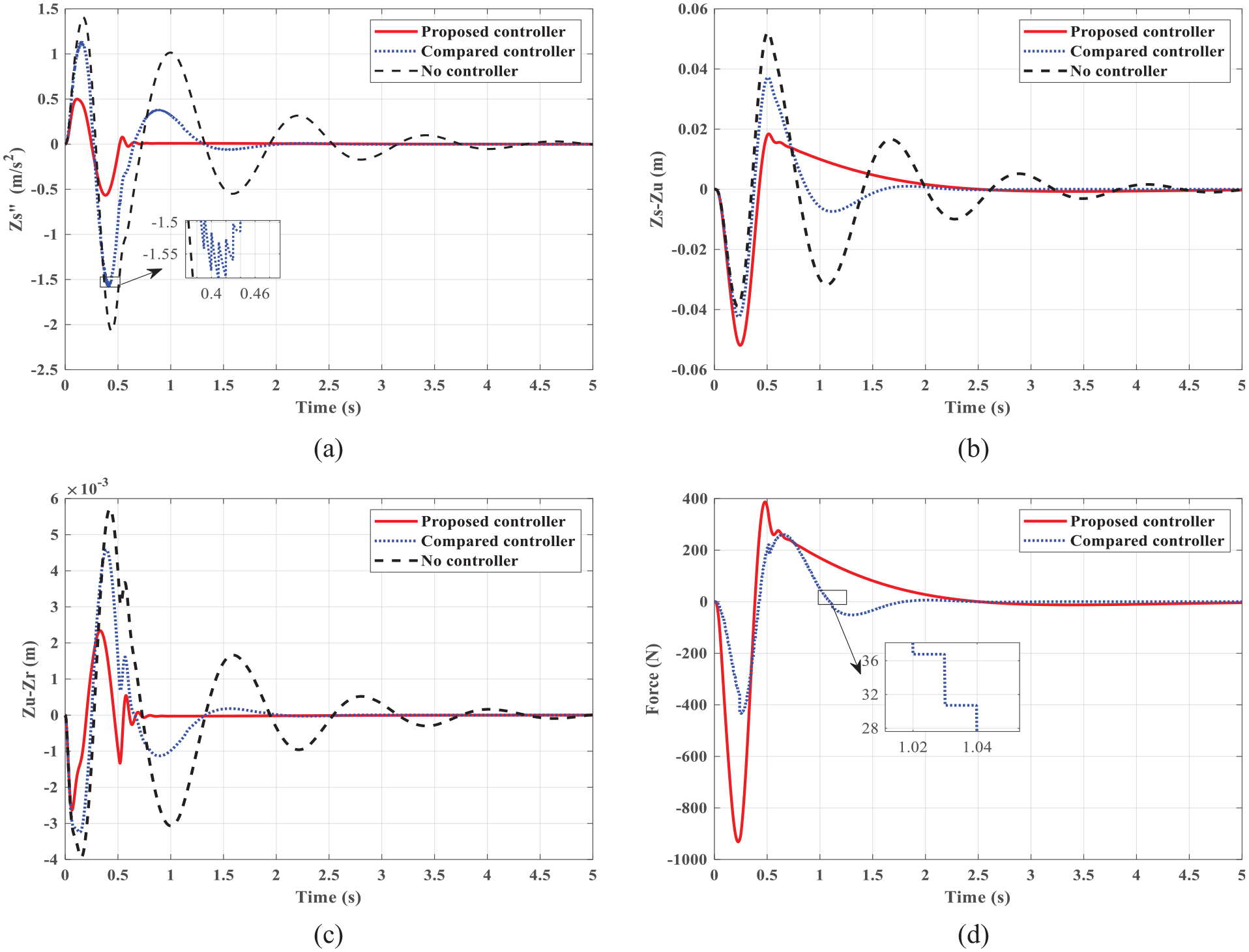
Bump response in Case 1: (a) sprung mass acceleration, (b)suspension travel, (c) tire deflection, and (d) actuator force.
Bump response in Case 2: (a) sprung mass acceleration, (b) suspension travel, (c) tire deflection, and (d) actuator force.
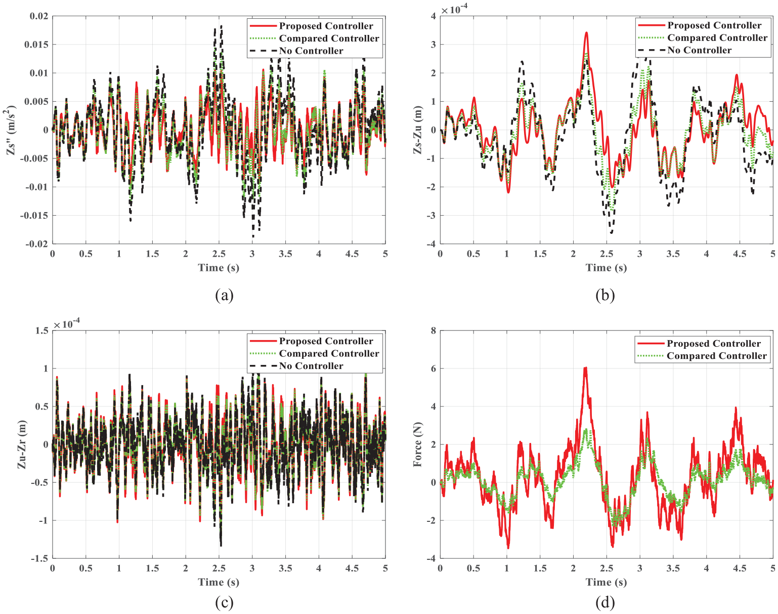
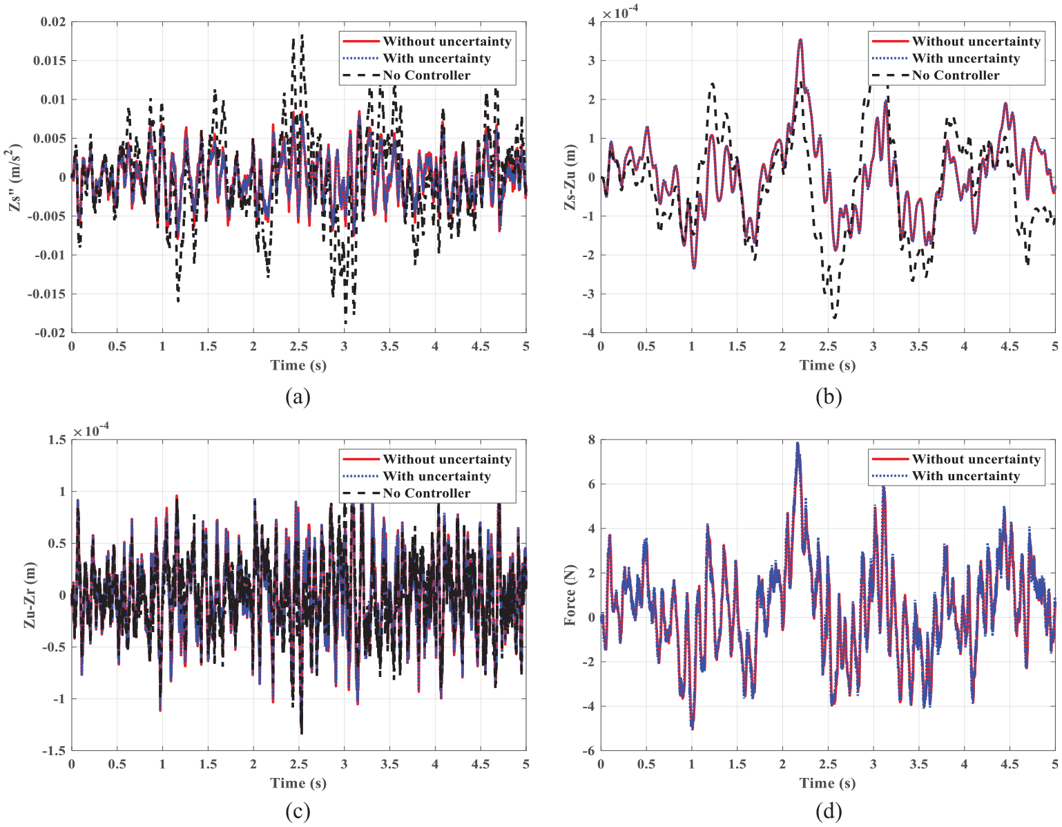
When the vehicle is driving on the road at varying speeds, the road profile will become a non-stationary process. To further evaluate the performance of the ASS, a random road is utilized to verify the ASS performance of the proposed controller. According to the simulation method of filtering white noise, the non-stationary road profile can be expressed as:
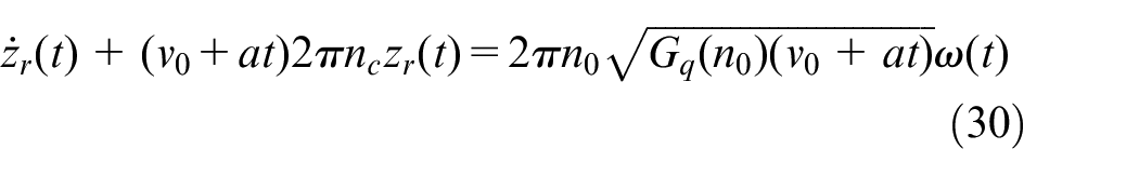
where V0 = 20 m/s represents the velocity, a = 4 m/s 2 represents the vehicle acceleration, n0 = 0.1 m--1 represents the normal spatial limiting frequency, nc=0.01 m--1 represents the road spatial limiting frequency, Gq(n0) represents the road roughness coefficient, ω(t) means the white noise time series. The A-class road roughness coefficient is chosen for simulation experiments according to ISO-2361. Similarly, in Figure 4, compared with the controller in Li et al., 29 the proposed controller can realize a smaller sprung mass acceleration. Figure 5 illustrates the actuator with uncertainty and time delay can make the same performance compared with the normal controller. It means that the proposed algorithm is more robust and practical. Both of them can keep the system stable and yield a less sprung mass acceleration. The non-fragile H2/H∞ controller can be able to improve the ride comfort. The mechanical limitations are also guaranteed at the same time. Therefore, the non-stationary response validates the effectiveness of the proposed ASS controller.
Non-stationary response in Case 1: (a) sprung mass acceleration, (b) suspension travel, (c) tire deflection, and(d) actuator force.
Non-stationary response in Case 3: (a) sprung mass acceleration, (b) suspension travel, (c) tire deflection, and(d) actuator force.
Moreover, the root mean square (RMS) can quantify the intensity of acceleration transmitted from a random road to the vehicle body, which is usually applied to reflect the ride comfort. Therefore, the RMS value is utilized to demonstrate the effect of the proposed controller. The RMS values can be described as follows:
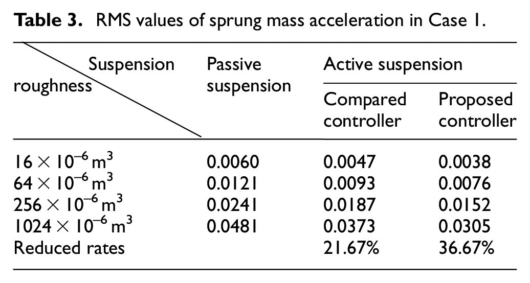
The Table 3 shows the sprung mass acceleration RMS values and the reduced ratio of the proposed controller, the compared controller and the passive suspension in Case 1. It clearly shows the RMS values of the proposed controller can be decreased by 36.67% and the compared controller is decreased by 21.67%. It highlights the effectiveness of the proposed controller. The above simulation experiments illustrate that the proposed controller can realize a better comprehensive performance than the compared controller and the passive suspension.
RMS values of sprung mass acceleration in Case 1.
Suspension plant experiments
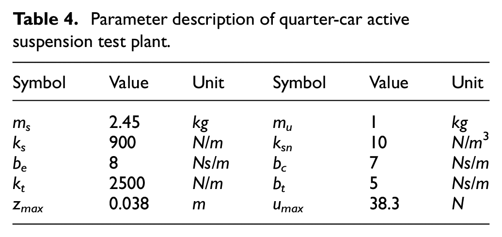
In this part, some suspension plant experiments are utilized to testify the effectiveness of the proposed controller. The experimental equipment is shown in Figure 6, and the diagram of the test plant is given in Figure 7. The plant parameters are presented in Table 4 according to Zhang et al. 36 For a better comparison, two different cases are listed in Table 5, and the sine wave disturbance and the pulse road input disturbance are designed to evaluate and verify the effectiveness and robustness of the proposed controller. By using a sine wave with a frequency of 3 Hz, the sine road input formula can be expressed as:

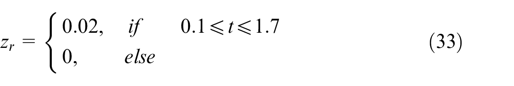
where h = 0.2cm represents the height of the vibration. The pulse road input formula with a period of 3 s can be expressed as:
Parameter description of quarter-car active suspension test plant.
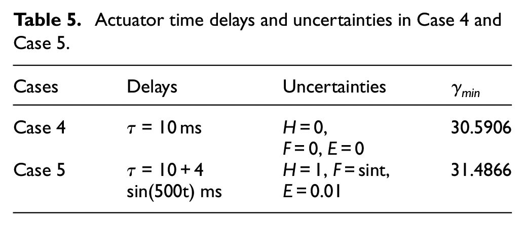
Actuator time delays and uncertainties in Case 4 and Case 5.
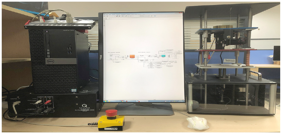
The quarter suspension test plant.
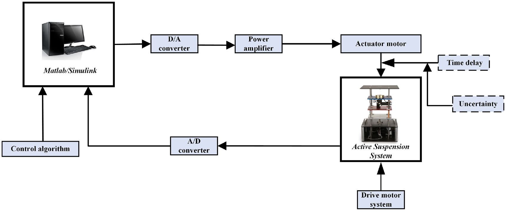
The diagram of test plant.
The pulse road input disturbance is given in Figure 8.
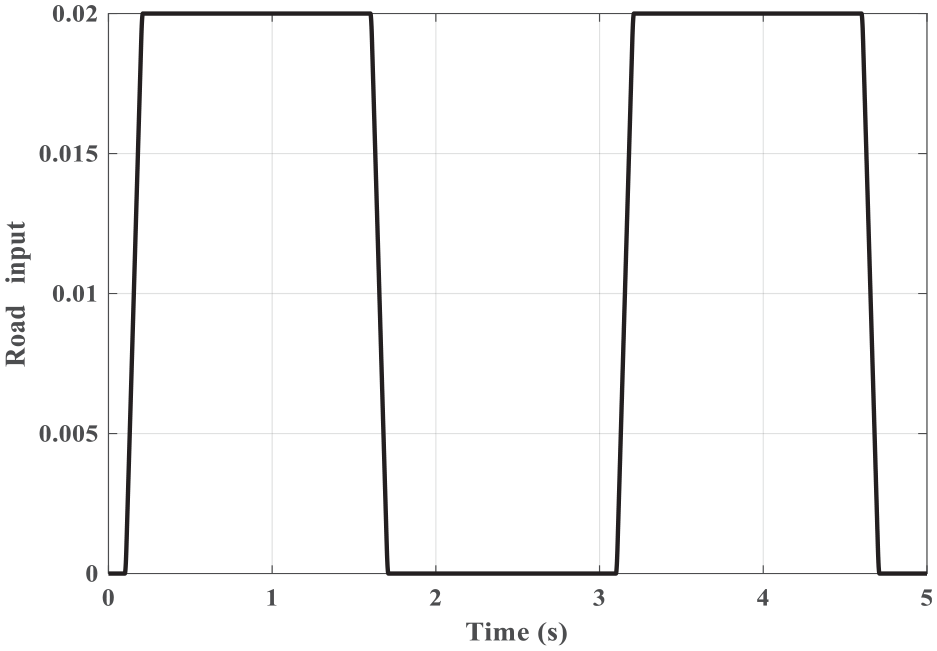
Pulse road input simulation.
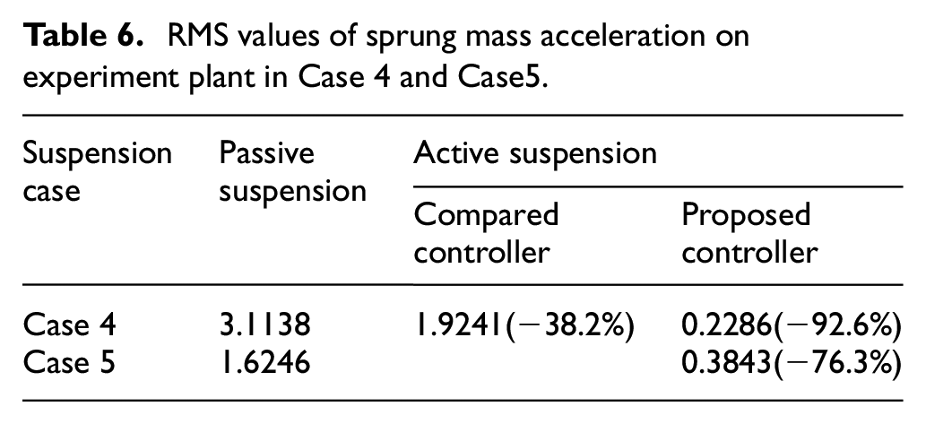
In Figure 9, the proposed controller can yield a much less sprung mass acceleration compared with the controller in Li et al. 29 and the passive suspension in Case 4, which denotes it can greatly contribute to realizing a better vehicle comprehensive performance and satisfy the physical constraints even if the actuator exists some time delays in the suspension system. It highlights the superiority of the designed algorithm. In addition, Figure 10 illustrates that the proposed controller is valid when the vehicle is driving on a road surface similar to the pulse form. It can provide better ride quality as compared with the passive suspension system. The RMS values and decreased ratios in Case 4 and Case 5 are presented in Table 6. It can be observed in Table 6 that the RMS values of the proposed controller can be largely decreased by 92.6% and the compared controller is decreased by 38.2% in Case 4. In Case 5, the RMS value is decreased by 76.3%.
RMS values of sprung mass acceleration on experiment plant in Case 4 and Case5.
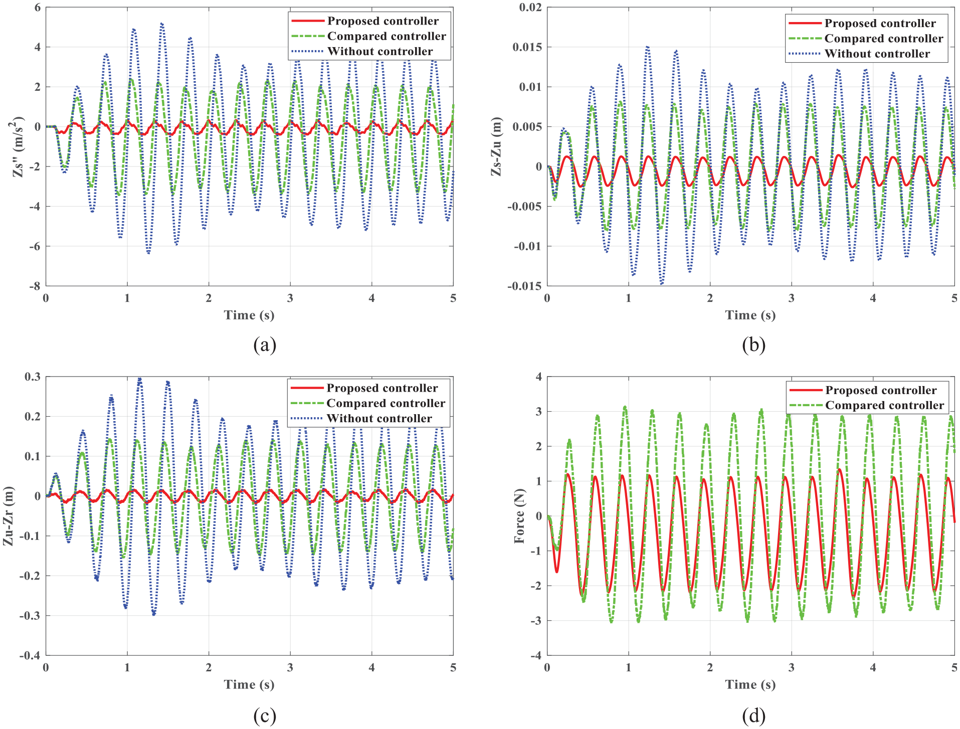
Sinusoidal response in Case 4: (a) sprung mass acceleration, (b) suspension travel, (c) tire deflection, and (d) actuator force.
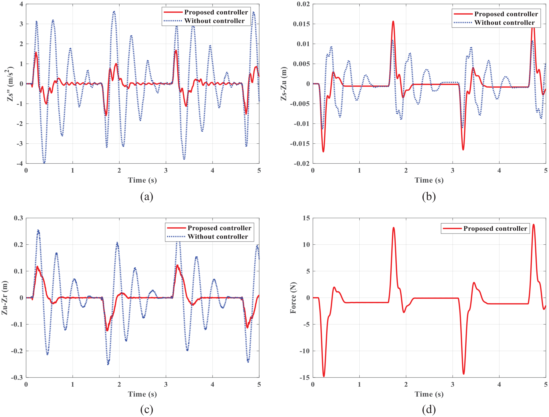
Pulse response in Case 5: (a) sprung mass acceleration, (b) suspension travel, (c) tire deflection, and (d) actuator force.
In conclusion, the whole experimental results manifest the effectiveness and robustness of the proposed controller.
Conclusions
In this work, the problem of fuzzy robust
Footnotes
Appendix A
if F satisfies
By Schur complement, the following formula can be written by
if and only if
and
Appendix B
where
According to the Leibniz-Newton formula, the following formula always holds
Moreover, the following equation is also satisfied in (10)
Then, taking the derivative of the equations (B.1), we can get
By using (B.5)–(B.7) and applying the equations (B.2)–(B.4), we can get the following equation:
where
By using lemma 3, we obtain
The following inequalities can be obtained by using the method in Niamsup and Phat 40
Then substituting (B.10–B.12) into (B.8), we can obtain
Furthermore, note that
where
considering the H∞ performance indicators, we can obtain
where
By using lemma 2, we can obtain
and
Further, a generalized
For all nonzero
where
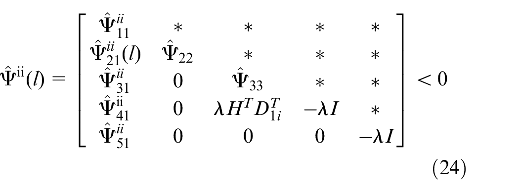
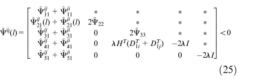
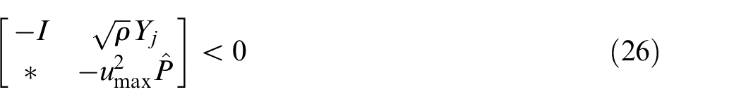
Then by Schur complement, (B.18) and (B.19) are equal to (25) and (26). The proof process is completed.
Declaration of conflicting interests
The author(s) declared no potential conflicts of interest with respect to the research, authorship, and/or publication of this article.
Funding
The author(s) disclosed receipt of the following financial support for the research, authorship, and/or publication of this article: This work is supported by National Natural Science Foundation of China (Grant No. 52175127), the Natural Science Foundation of Guangdong Province of China (Grant Nos. 2022A1515011495, 2021AA151500583), the Joint Project of Natural Science Foundation of Liaoning Province of China (Grant No. 2021-KF-11-02), the Fundamental Research Funds for the Central Universities (Grant No. N2203012), and the Research Grant of the University of Macau (Grant No. MYRG2020-00045-FST).