
Abstract
At hypersonic speeds, the external wall temperatures of an aerospace vehicle vary significantly. As a result, there is a considerable heat transfer variation between the boundary layer and the wall of the hypersonic vehicle. In this article, numerical computations are performed to investigate the effect of wall temperature on the separation bubble length in laminar hypersonic shock-wave/boundary-layer interaction flows over double-cone configuration at the Mach number of 12.2. The flow field is described in detail in terms of different shocks, expansion fans, shear layer and separation bubble. The variation of the Prandtl number has a negligible effect on the flow field and wall data. A specific heat ratio of less than 1.4 results in the better prediction of wall pressure and heat flux in the shock/boundary-layer interaction region. It is observed that as the wall temperature is increased, the separation bubble size and hence the separation shock length increases. The high firmness of the laminar boundary-layer at a high Mach number shows that the wall temperature in the shock/boundary-layer interaction region has little effect. The peak wall pressure and heat flux decrease with an increase in wall temperature. An estimation is developed between separation bubble length and wall temperature based on the computed results.
Keywords
Introduction
Shock/boundary-layer interactions cannot be circumvented in supersonic and hypersonic practical flows such as scramjet intakes, re-entry vehicles, nozzles and launch vehicles. Owing to low densities at higher altitudes, laminar boundary-layers are formed over vehicle walls. The shock waves are generated at high Mach numbers at compression surfaces from different parts of the vehicle. These shock waves formed in the vehicle, when they encounter the laminar boundary-layer, can result in flow separation, thereby generate high wall pressure, skin friction and heat flux in the interaction region. 1 Therefore, an accurate prediction of wall pressure and heat flux in the shock/boundary-layer interaction helps in the design of the thermal protection system of hypersonic vehicles and, hence, requires a detailed understanding of the flow.
A shock wave interaction with a laminar boundary layer is more susceptible to flow separation because of its low resistance to the adverse pressure gradient across the shock wave contrary to turbulent boundary layers. 2 Numerical prediction of laminar boundary layer separation is a greater challenge in the hypersonic regime because of strong interactions with shock waves and boundary layers formed on the walls.3,4 Hypersonic vehicles flying at higher altitudes experience different wall temperatures. The wall temperature can change from 300 to 467 K at the Mach number of 7. 5 Surface heat transfer calculations were calculated at flight velocities ranging from 1768 to 6950 m/s and wall temperatures varying from 300 to 3000 K. 6 The effective way of cooling the vehicle surface at high Mach numbers is through the transmission of the fluid mass from the vehicle surface to the boundary layer. This transfer of mass can be performed by various techniques such as film cooling, transpiration cooling and ablation. 7
A detailed parametric study on laminar hypersonic shock/boundary-layer interaction flows for different canonical flow configurations like double cone and cylinder flare has been reported in the literature.8–10 The real gas effects at high-enthalpy flow on separated flows in shock/laminar boundary layer interaction flows were studied computationally in detail and an improvement in the results was made by including the non-equilibrium effects over double-cone configurations with Mach numbers in the range of 6–9.11–13 It is observed that the dissociation of air occurring behind the reattachment shock decreases the corresponding pressure and causes a decrease in the separation length as compared to frozen flows. At hypersonic speeds, a fourfold increase in wall temperature resulted in a fourfold increase in separation bubble size in shock/turbulent boundary-layer interaction flows over compression corner configurations. 14
The objective of this work is to numerically study the effect of boundary layer heating by altering the surface temperatures on the separation bubble length in the shock-wave/laminar boundary-layer interaction region. This article is organized as follows: First, the numerical methodology is described. Next, the computed flow field is described. Then, the variation of the Prandtl number and the specific heat ratio is discussed. This is followed by a comparison of the surface pressure, heat transfer and skin friction with experiments. The effect of variation of wall temperature is discussed next. This is followed by the correlations established from the present computations and, finally, the conclusions and the future work are discussed.
Numerical methodology
Recent experimental studies were conducted by MacLean et al. 15 in an expansion tunnel at high-speed laminar air flows with velocities ranging from 3 to 6.5 km/s over double-cone configuration as shown in Figure 1. The conditions replicate the re-entry vehicles at an altitude of more than 45 km and correspond to low-density flows. The measurements include well-defined boundary conditions (see Table 1), surface heat flux and pressure measurements made in large separated regions of the shock wave/laminar boundary layer interaction region and provide a good dataset to compare with the Navier–Stokes computations. The studies include the effects of non-equilibrium air chemistry for high-enthalpy test cases.

Double-cone (25°–55°) experimental configuration 15 considered in the current computations.
Freestream and wall conditions used in the current numerical simulations. 15

The present computations are performed by solving the two-dimensional axisymmetric laminar Navier–Stokes equations for mean flows.16,17 The 25°–55° double-cone experimental configuration of MacLean et al. 15 is chosen in the numerical simulations. The code used in the computations can be run on parallel machines using the message passage interface. 18 The equations are discretized using a finite volume method, where the inviscid fluxes are computed using a low-dissipation form of the modified Steger–Warming flux splitting scheme and are second-order accurate in both the streamwise and wall-normal directions. The implicit method is used to integrate in time and to reach a steady-state solution. Owing to a low enthalpy, a calorically perfect gas (frozen gas with no chemical reactions) is assumed in the simulations with a gas constant of 287 J/kg K. Fourier’s law of heat conduction is used to calculate the wall heat flux and the viscosity is calculated using Sutherland’s law. In our work, the wall temperature Tw is varied from 250 K to adiabatic wall temperatures to study its effect on the laminar shock/boundary-layer interaction region formed at the cone–cone junction. The code has been used and validated in several supersonic and hypersonic shock/boundary- layer interaction flows.19–21
The number of grid points is increased in both the streamwise and normal directions from 900 × 300 to 1300 × 500 until the solution is independent of the grid as shown in Figure 2. Therefore, based on the grid convergence study, there is a less than 1% difference between 1300 × 500 and 1100 × 400 grids. Hence, we employ 1100 × 400 grid points in the computational domain with 1100 points along the streamwise direction and 400 points in the wall-normal direction. The grid is exponentially stretched in the wall-normal direction with a first cell size of 1 × 10⁻⁶ m at the wall. Also, the grid is stretched along the axial direction on either side from the corner of the double cone with a minimum cell size of 5 × 10⁻⁴ m.
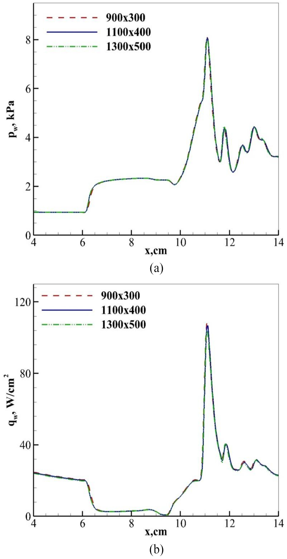
Effect of grids on the (a) surface pressure and (b) surface heat flux at Tw = 300 K.
Results and discussion
In this section, the flow field is described in detail and the Prandtl number and specific heat ratio are varied to check their influence on the computed results. Next, the baseline case with a wall temperature of 300 K is computed and compared with the experiments. Next, the wall temperature is varied in the computations to study its effect on the separation bubble length and a correlation is observed.
Flow field
The intricate region of the laminar shock/boundary layer interaction region is presented in Figure 3 in terms of pressure and velocity contours. It is observed that the shock formed at the tip of the double cone is very close to the boundary formed on the wall and thereby results in a very thin shock layer. This is one of the characteristics of hypersonic flows. 22 The shock-induced pressure rises at shock formed in the corner of the double cone produce a separation region by interacting with the upstream laminar boundary layer formed on the wall of the cone. The flow separates in the separation region (S) and attaches in the reattachment region (R). The subsonic separation bubble forms an obstacle to an upstream hypersonic flow and acts as a compression ramp at the corner. This bubble results in the formation of separation shock. The shock generated at the cone tip interacts with the separation shock to form a shock–shock interaction. Also, the separation shock interacts with the shock formed at the corner to form a shock–shock type VI interaction. 23 A free shear layer and a shock wave are generated in this shock–shock interaction. The shock emanating from this interaction interacts with the boundary layer formed on the second cone and reflects as a shock wave. Peak pressure is observed at this point. This shock interacts with the free shear layer flowing parallel to the wall and reflects as an expansion fan. The Mach waves from the expansion fan combine to form a shock wave that interacts with the boundary layer on the cone and reflects as an expansion fan. This expansion fan crosses the shear layer and interacts with the reattachment shock at the corner and modifies its shock shape from its inviscid straight line to the convex structure.

Computed (a) pressure and (b) velocity contours at Tw = 300 K.
Effect of Prandtl number
There can be uncertainties in the wall data measurement with the variation of thermodynamic properties as a function of wall temperature at hypersonic speeds over blunt bodies. 7 It is observed that at temperatures above 2000 K at a speed of about 18 km/s, the variation of coefficient of thermal conductivity by a factor of 10 results in an increase of 40% in the stagnation point heating rate. 24 It can be seen from Figure 4 that the variation of Prandtl number has a negligible effect on the wall pressure and heat flux. The formulation of the Prandtl number dependence on temperature in earlier studies showed that it had a negligible effect on laminar hypersonic shock/boundary layer interaction flows over cylinder-flare configuration. 25

Effect of Prandtl number on the (a) surface pressure and (b) surface heat flux with a specific heat ratio, γ = 1.4, at Tw = 300 K.
Effect of specific heat ratio
The real gas effects are important for a vehicle flying at hypersonic Mach numbers in the air, and the value of γ will be different from 1.4. The predicted shock standoff distance calculated using a specific heat ratio, γ = 1.4, was 26% higher than that of experimental measurements at the stagnation point. However, approximating the real gas effects using an effective value of γ = 1.275 resulted in a shock standoff distance at the stagnation point to within 4% than the measurements. 5 The peak hypersonic aerodynamic heating experienced by manned vehicles at low-density flows, especially at more than 45 km altitude in the continuum flow regime, can change the specific heat ratio of gas due to dissociation and combination of oxygen and nitrogen molecules of air.
In this work, the air is assumed to be a perfect gas and the real gas effects are accounted for by varying the specific heat ratio, γ. It can be seen from Figure 5(a) that the lower values of γ result in lower values of wall pressure, upstream of the interaction region for x < 6 cm. It is because the pressure ratio across the first cone shock results in lower values with lower values of γ as compared to that of 1.4. In the reattachment region, at x = 11 cm the peak pressure rise is lower with γ = 1.23 as compared to γ = 1.4. It is observed that the pressure rise across separation shock is better predicted with γ = 1.275 as compared to γ = 1.4 because of a better inclination of separation shock as shown in Figure 6. Therefore, a value of γ = 1.275 gives a better prediction of wall pressure in the plateau region between x = 6 and 10 cm. On the contrary, it can be seen from Figure 5(b) that lower values of γ result in higher values of heat flux, upstream of the interaction region (x < 6 cm) and in the reattachment region (x = 11 cm). Overall, a value of γ = 1.275 gives a better prediction of computed wall data and is used in further calculations. The effect of specific heat ratio dependence on temperature in the shock/boundary-layer interaction region will be studied in our future work.

Effect of specific heat ratio, γ, on the (a) surface pressure and (b) surface heat flux at Tw = 300 K.

Effect on shock structure with the variation of specific heat ratio γ = 1.4 (red colour) and γ = 1.275 (blue colour) at Tw = 300 K.
Computed surface data at a wall temperature of 300 K
The laminar boundary layer is often frozen at low-enthalpy flows due to the least chemical reactions between air molecules, and therefore there is a slight effect of real gas on hypersonic flows. However, we assume a perfect gas in the simulations and a Prandtl number of 0.71 and take the real gas effects by assuming γ = 1.275. The experiments over the 25°–55° double-cone configuration were conducted at a wall temperature of 300 K. 15 In this section, we compare the computed results (baseline case) at the same wall temperature as taken in the experiments, that is, at Tw = 300 K.
The computed wall pressure in Figure 7(a) remains constant up to x = 6.2 cm and starts to increase across separation shock and matches very well with the experiments. 15 It remains constant in the separation region up to x = 9.7 cm and shows a small drop at the double-cone junction because of secondary flow separation (see Figure 6). The pressure rises across weak compression waves downstream of the corner. It reaches a peak value at x = 11 cm downstream of the reattachment region R, where a shock wave emanating from the shock–shock interaction interacts and reflects at the wall. The pressure drops downstream of x = 11 cm across expansion fans as observed in the inset of Figure 3. These drop and rise in pressure occur across a train of shocks and expansion fan formed between the wall boundary layer on the second cone and free shear layer (see Figure 3) and diminish due to a reduction in Mach number in the downstream direction.

Computed (a) surface pressure, (b) surface heat flux and (c) skin friction at a constant wall temperature, Tw = 300 K, Pr = 0.72 and γ = 1.275 compared to the experimental data at Tw = 300 K. 15
The computed wall heat flux, qw, in Figure 7(b) decreases from the cone tip up to x = 6 cm, due to an increase in the thermal boundary thickness, which thereby reduces the temperature gradient near the wall. The computed qw value is predicted to be lower as compared to the experimental data. It may be because, in the computations, the heat flux is calculated based on Fourier’s law of heat conduction. The lower values of heat flux near the reattachment region at x = 11 cm as compared to experiments may be because of the dissociation of air molecules at a high temperature in this location, which our computations neglect. Further investigations are required in this area by considering the chemically reacting air in the simulations. 21 This is beyond the scope of this work. The drop and increase of qw downstream of x = 11.5 cm is due to the increase and decrease of temperature across alternate shocks and expansion fans.
The response of the laminar boundary layer on the first cone surface to an adverse pressure gradient across shock at the corner of the double cone depends on the viscous force, which is characterized by the skin friction coefficient, Cf, as shown in Figure 7(c). The boundary layer thickness, δ, increases from the tip of the double cone before the shock/boundary-layer interaction at the second cone because of a decrease in the velocity gradients near the wall region. The δ value decreases up to x = 6.2 cm, drops drastically and reaches zero at flow separation S where the velocity gradient asymptotes to zero. The Cf value is zero in the reattachment region R and increases downstream of it due to high-velocity gradients in the compressed boundary layer across reattachment shock at x = 11.5 cm. Cf shows a wave pattern downstream of R due to a decrease and an increase in velocity across shocks and expansion fans. Note that Cf is not measured in the experiments. 15
Effect of wall temperature
Different wall temperatures, Tw, from 250 K to an adiabatic wall temperature of 3193 K, are simulated in current computations. The adiabatic wall temperature is calculated by assuming a recovery factor of Pr1/2 and γ = 1.275. 7 The heat flux contribution from diffusion (real gas effects) is neglected. It can be seen from Figure 8(a) that as the wall temperature is increased, the initial pressure rise location shifts upstream of the interaction region and reaches a value of x = 4.5 cm for the adiabatic wall temperature. The higher wall temperature increases the length of separation shock and shifts the shock–shock interaction region downstream as shown in Figure 9. Therefore, the peak surface pressure and heat flux values in Figure 8(a) and 8(b) are shifted in the downstream direction.

Effect of variation of wall temperatures on the computed wall (a) pressure and (b) heat flux compared to the experimental data of MacLean et al. 15

Effect on shock structure with a variation of wall temperature at Tw = 300 K (red colour), 1200 K (blue colour) and at adiabatic (ADIA) wall temperature (green colour) with γ = 1.275.
As the wall temperature is increased, the density near the wall is decreased making the flow more laminar, thereby decreasing the Reynolds number. This results in the decrease of velocity gradients as shown in Figure 10(a). The shear forces tend to oppose the retardation effect of the shock wave. The resistance of the laminar boundary layer to an imposed pressure gradient across shock diminishes with an increase in Reynolds number at higher wall temperatures and therefore results in the larger size of separation bubble in the corner of a double cone. Also, the thick boundary layers at higher wall temperatures result in a larger separation region as compared to a thin boundary layer at a lower temperature. Hence, the skin friction variation in Figure 10(b) indicates that the region between S and R is increased, thereby increasing the size of the separation bubble with an increase in wall temperature. The separation length Ls is measured between the separation (S) and reattachment (R) regions in the skin friction plots where its value asymptotes to zero.

Effect of variation of wall temperatures on the computed (a) velocity profiles and (b) skin friction coefficient.
Estimation
The separation length increases by 5% when its wall temperature Tw is doubled from 300 to 600 K and increases by 50% when Tw is increased ∼10 times (adiabatic wall temperature) as shown in Figure 11. An estimation is formulated from the exponential curve fit between the separation length Ls and the wall temperature Tw and shows a good match with the current computed results. Also, higher wall temperatures result in an increase in boundary layer thickness.

Effect of variation of wall temperatures on the computed separation length, Ls, and boundary layer thickness, δ0, upstream of the shock/boundary layer interaction region.
An estimation between Ls/δ0 and Tw/Tadia is shown in Figure 11 to match the computational results

where Tadia is the adiabatic wall temperature and δ0 is the boundary layer thickness at Tw = 300 K.
Future work
The physical mechanism of heat transfer differs from the molecular heat conduction process at high-Mach flows in comparison to subsonic flows. At higher altitudes, lower pressures result in an increased dissociation of air. At hypersonic speeds, the air that passes through the strong shock wave gets heated and dissociates the air molecules into oxygen and nitrogen atoms. When these atoms and the other intermediate species are formed, they diffuse through the boundary-layer into the cooler region near the wall and combine to form molecules. The heat released as a result of this recombination of atoms can contribute significantly to the wall heat flux. Therefore, at high-speed flows, the convective heat transfer mechanism consists of both the conduction and the diffusion (due to molecule breaking and atom recombination) process. The Lewis number is defined as the ratio of energy transported by diffusion to that by conduction and is an important parameter in high-speed calculations, which can be varied to study its effect on shock/boundary layer interaction flows. This forms the basis of our future work, to study the real gas effects at high-enthalpy shock/boundary-layer interaction flows by simulating the chemically reacting gas.
Conclusion
Numerical computations are performed to investigate the effect of wall temperature on the separation bubble length in laminar hypersonic shock-wave/boundary- layer interaction flows over double-cone configuration at the Mach number of 12.2. The flow field is described in detail in terms of different shocks, expansion fans, shear layer and separation bubble. The variation of the Prandtl number has a negligible effect on the flow field and wall data. A specific heat ratio of less than 1.4 results in the better prediction of wall pressure and heat flux in the shock/boundary-layer interaction region. It is observed that as the wall temperature is increased the separation bubble size and hence the separation shock length increase. The high firmness of the laminar boundary layer at a high Mach number shows that the wall temperature in the shock/boundary-layer interaction region has little effect. The peak wall pressure and heat flux decrease with an increase in wall temperature. An estimation is observed between separation bubble length and wall temperature based on the computed results.
Footnotes
Appendix 1
Acknowledgements
The authors would like to thank the High-Performance Center staff for providing us the Aziz supercomputing facility to perform the numerical simulations. The authors would also like to thank Professor Krishnendu Sinha from the Department of Aerospace Engineering, Indian Institute of Technology Bombay for his kind help. The authors gratefully acknowledge the technical and financial support of Deanship of Scientific Research, King Abdulaziz University.
Handling Editor: James Baldwin
Declaration of conflicting interests
The author(s) declared no potential conflicts of interest with respect to the research, authorship and/or publication of this article.
Funding
The author(s) disclosed receipt of the following financial support for the research, authorship and/or publication of this article: This project was funded by the Deanship of Scientific Research, King Abdulaziz University, Jeddah, under Grant No. DF-041-135-1441.