
Abstract
The aim of this article is to investigate the characteristics of checkweigher which consists of two parts: electrical part (voice coil actuator) and mechanical part (lever-pivot mechanism). Its integrated weighing system simplified m, c, and k model, and system identification is performed through comparison of experimental results and simulated results by Simulink. m and k are attributed to the mechanical part and c is mainly due to the electromagnetic damping of voice coil actuator. Even with a determined voice coil actuator, the damping effect can be adjusted by the relocation of voice coil actuator to improve the performance of checkweigher. The validity of the simplified model is verified by comparing simulation and experimental results.
Introduction
Weighing technology has been essential for manufacturing of standardized packed products in the electronic, food, and pharmacy industry. Since the industrial era, there have been new ways to measure mass which started from spring scales to electronic systems for more accurate and faster performance. A checkweigher is a system weighing items as they pass through a production line, additionally classifying objects by preset weight zones, and ejecting or sorting things based on classification. Because the in-motion products must be measured during a short time while they are traveling over the weighing spot, many troubles are caused due to vibration and inconsistent measuring timing. Along with increasing application of checkweighers, dynamic weighing technology was adopted to improve its performance of productivity and accuracy.
Generally, two types of measurement system associated with checkweigher are deflection and balancing type. In the load cell system based on deflection type, the relationship of elastic deformation and spring constant is used to measure a wide range of mass. The deflection type is simple in mechanism and fast in speed but less accurate. On the contrary, the balancing type in which an actuator generates a counter force to keep a pivoted lever balanced against a loaded mass has the advantage of high accuracy but less speed. Voice coil actuators (VCAs) are used due to its fast response and linear motion. 1 VCAs are used due to its fast response and linear motion.2,3 Through measurement of current flow in the VCA, both compensation force and the weight force are determined. 4
Many research efforts have been devoted to the estimation of weight and studied about removing noise and modeling spring, mass, and damper on dynamic weighing.5,6 The effect of the sensor in different locations on the ability of dynamic weighing was investigated. 7
This research focuses on developing an integrated model of mechanical part and electrical part and simplifying it as an m, c, and k model. To improve its performance, it is necessary to identify the system parameters and based on the system model, the effect of each parameter is examined.
Structure of a balanced type checkweigher
Configuration of measurement system
Figure 1 shows a scheme of a balanced type checkweigher which is composed of the lever mechanism, VCA, laser displacement sensor, conveyor, and balancing compensation controller. The lever mechanism includes such elaborate parts as hinge and pivot to make a large displacement even for a tiny mass loaded on the weighing pan. The VCA is controlled to compensate a gap from the balanced position caused by a mass.

Scheme of checkweigher system.
Measuring principle
A mass loaded on the weighing pan causes a small clockwise rotation of the lever around the pivot, which results in a large displacement of the measuring spot, measured by a laser displacement sensor. Then the VCA is controlled to compensate the displacement so that the lever returns to the balanced position with zero displacement. During compensation, a current depending on the displacement is flown through the coil of VCA to generate a corresponding Lorentz force, which is proportionally related to the weight of the mass. Finally, an unknown mass can be estimated from the current which is detected by a resistor sensor. The important things are how fast and how accurately it is measured. They are the fundamental characteristics for the performance of evaluating weighing systems.
System modeling and simulation model
System modeling
The checkweigher system needs to be modeled and identified to investigate the performance. It is composed of two units: one is a mechanical unit by which displacement is generated and amplified responding to a loaded mass and the other is an electrical unit of VCA which compensates a gap displacement. Its dynamic model is simplified as shown in Figure 2 where a hinge is modeled as a spring (K), electromagnetic damping (c), and Lorentz force (FVCA) are generated by the VCA.
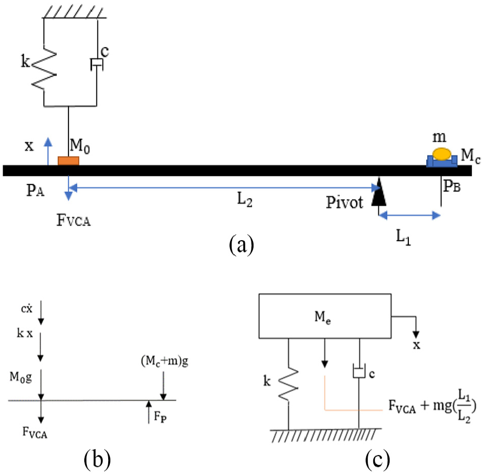
Motion model of the weighing system in a checkweigher: (a) rotational motion model about a pivot, (b) free body diagram, and (c) rectilinear motion model.
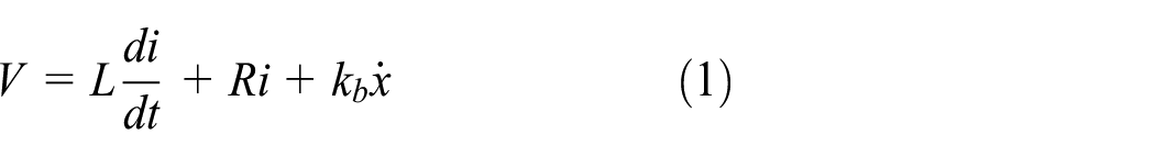
Electrical modeling of VCA
The electric model of VCA can be expressed as equation (1) 3
Here

An equivalent circuit of a voice coil actuator.
Force–current relationship of VCA
To investigate the relationship between current and force of the VCA,

Force and current relation of voice coil actuator.
From the linear regression analysis, FVCA has a linear relationship with current where kf = 28.5 N/A. FVCA is different according to the position of bobbin from the center of coil length even under the same current. Figure 5 shows the experiment results of FVCA depending on the location of bobbin. It means that the proper operating region is limited to ±0.5 mm from the center.

Variation of FVCA according to bobbin displacement from the center: (a) bobbin displacement and (b) force variation.
Mechanical modeling of lever motion
The lever mechanism is initally condition with x = 0, m = 0, and FVCA = 0, M0L2 = McL1, where Mc is conveyor mass and M0 is a required counter mass including lever mass. Setting Mc = 4.0 kg, L1 = 3.5 mm, L2 = 97.7 mm, then M0 is calculated as 0.15 kg.
As an object (m) is loaded on the weighing pan, a balancing control starts. The force and moment equilibrium are expressed in equations (2) and (3) based on the free body diagram depicted in Figure 2(b)


The rotational motion of lever is described as follows

where the inertia of lever
Substituting MP and I in equation (4)

Since the rotation of movement of lever is too small,

Thus, as depicted in Figure 2(c)

where
Simulation model
To investigate characteristics and performance of the weighing system, its dynamic properties of Me, c, and k as depicted in Figure 2(c) should be identified through comparison of simulation and experimental results. Thus, each simulation model is induced through the Laplace transform of the governing equation of electrical and mechanical models.
VCA actuation model
Equation (1) is transformed into equation (8)

Electrical specification about VCA is L = 0.0245 H, R = 28.9 Ω, kf = 28.5 N/A, and kb = 28.5 V s/m.
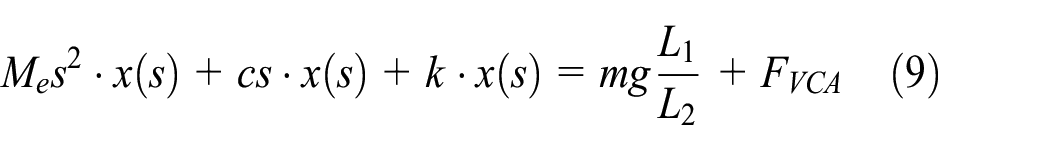
Lever motion model
Equation (7) is transformed into equation (9)
Simulink model
Combining equations (8) and (9), a simulation model of the weighing system is represented by a Simulink program, as shown in Figure 6.

Simulink model of weighing system.
Experiment setup
Figure 7 shows a photograph of the measurement system setup. A laser displacement sensor is used to detect lever movement. A VCA is used to compensate a deflection gap generated by lever movement. The current through VCA coil generating Lorentz force is measured by a resistor sensor. NI VirtualBench is used to generate step input current.

Experimental setup.
Estimation of spring constant
To investigate the spring constant (K), experiments are conducted to obtain displacement with respect to five different weights. The force of each weight loaded on the weighing pan is converted into equivalent force at PA. The displacement at PA is measured by laser displacement sensor. Based on the experimental results listed in Table 1, a linear relationship is shown in Figure 8 and K is calculated as 1453 N/m through regression analysis.
Experimental results of weights versus displacement.


Relation between force and displacement.
Effect of back electromotive force of VCA
The effect of back electromotive force (BEMF) kb in Simulink model needs to be examined. Figure 9 shows how fast the current flows through the VCA coil as a voltage is applied to VCA by considering kb as 28.5 and kb as 0. kb tends to hinder the current flow resulting in slow response.

Effect of kb on current flow.
Estimation of damping coefficient
Setting m = 0 in equation (9), a step value of FVCA is applied to get a step response because a step voltage can be easily and precisely input to VCA through NI Virtual Bench by LabVIEW algorithm. Me is already determined as 0.155 kg in section “Mechanical modeling of lever motion.”
With the previously identified parameters, Me = 0.155 kg and K = 1453 N/m, the damping coefficient can be identified through comparison between the simulated response to a step FVCA and the corresponding experimental response. With a step input of 3 mA to VCA, the measured step response seems quite overdamped, as shown in Figure 10. In order to identify the damping coefficient, simulations are repeated with several values of 16.5, 26.5, and 36.5 and the results are displayed together in Figure 10. From comparison with the experimental data, the best estimated damping coefficient is 26.5 N s/mm, which corresponds to damping ratio of 0.89.
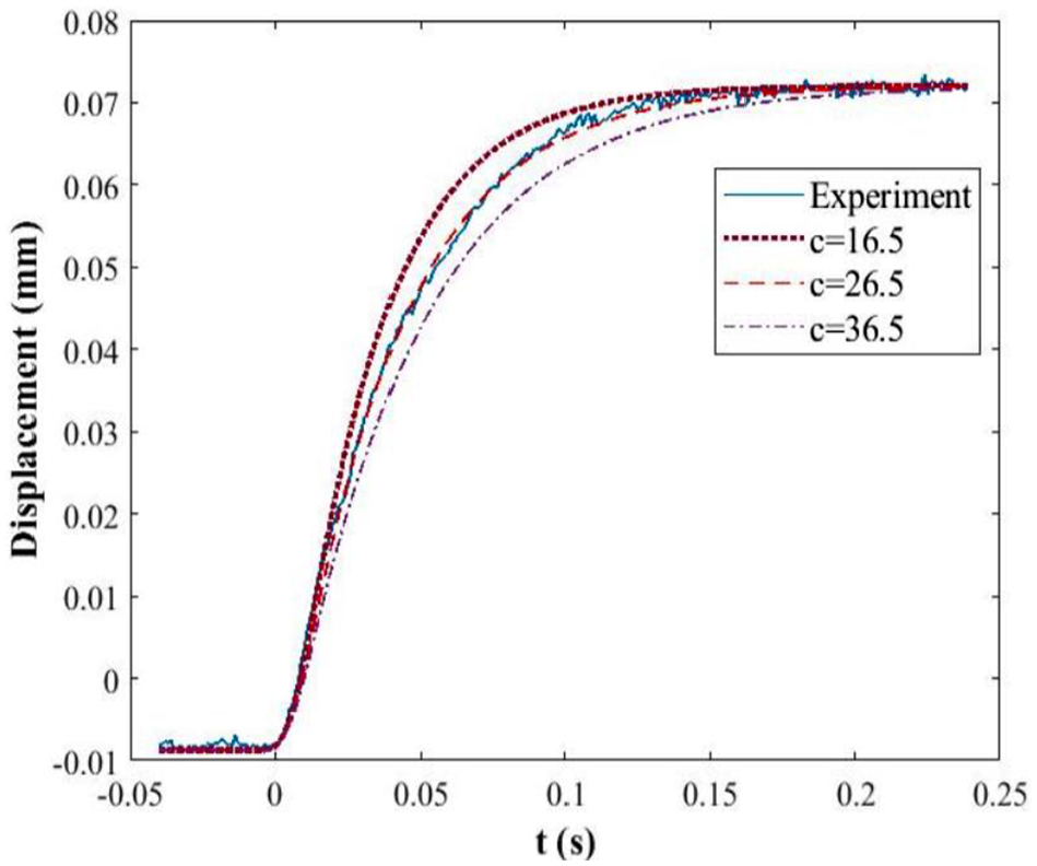
Identification of damping coefficients for a step input of 3 mA.
Figure 11 shows an improper step response which goes beyond the proper operating region (±0.5 mm) of VCA and the real damping effect lessens. Thus, considering less step input of 3 mA has good similarity with the simulation results.

Improper step response for a large input as much as 30 mA.
Effect of relocation of VCA
Under the condition of a determined VCA, relocation of VCA could be an available way to reduce the damping coefficient of the overdamped system as described in section “Estimation of damping coefficient.” To examine the effect of VCA relocation (from L2 to L3), simulation is carried out for two locations, L3 = 71.8 and 89.8 mm (Figure 12). As shown in Figure 13, both simulation results correspond to the less damping ratios, that is, 0.68 and 0.78, respectively, compared to the actual response at L2 = 97.7 mm.

Partly modification of Simulink model for investigating the effect of relocation of VCA.

Response of relocation of VCA.
Conclusion
For a balanced type weighing system by VCA, system modeling and identification are presented and validated with simulation and experiment. The rotational motion of lever is converted into the rectilinear motion with Me, c, and K. Based on this model, system identification of checkweigher can be carried out at an early stage of development. The new findings are as follows:
The system parameters are identified as Me = 0.155 kg, K = 1453 N/m, and c = 26.5 N s/mm (or damping ratio = 0.89) resulting in an overdamped system.
Even in the case of VCA given, adjusting the position of VCA from the pivot can keep the system under proper damping. The closer to the pivot is the position of VCA, the less is the damping.
The stable operating range of VCA used in this research is ±0.5 mm beyond which experimental and simulated results show no conformity.
Footnotes
Handling Editor: James Baldwin
Declaration of conflicting interests
The author(s) declared no potential conflicts of interest with respect to the research, authorship, and/or publication of this article.
Funding
The author(s) received no financial support for the research, authorship, and/or publication of this article.