
Abstract
This paper explores implementing active resonance frequency tuning of adaptive tuned vibration absorbers (ATVA) by coupling a vibration absorber comprising a voice coil actuator (VCA) and a sprung inertial mass to a solenoid actuator (SA). In this device, the DC current flowing through the SA generates negative magnetic stiffness and varies the equilibrium position of the nonlinear spring of the VCA, thus changing the effective stiffness of the system and its resonant frequency. The paper details the analytical design steps and the parametric sizing process of designing the SA to maximize its force density within defined magnetic, dimensions and thermal constraints. The design of the SA was verified using finite element analysis (FEA), manufactured and coupled to a VCA to make the complete ATVA system. The experimental results demonstrate the tunability of the resonance frequency of the ATVA by controlling the SA’s DC current. It is shown that the system’s resonance frequency can be shifted by up to 23% of the fundamental resonance frequency, which improves the effectiveness of the ATVA at damping a broader range of excitation frequencies.
Keywords
1. Introduction
The tuned vibration absorber (TVA) is a vital engineering tool for vibration suppression. This device often consists of a reaction mass and a spring element with appropriate damping (Han et al., 2015). When the resonance frequency of a TVA is adjusted to match the structure’s excitation frequency, the actuator’s gain is maximized, that is, the current and power needed to generate the desired reaction force to mitigate the host’s vibration are significantly reduced. Conversely, the actuator generates a resonant reaction force that is considerably larger than that generated at off-resonance for given rated current and power. This system has been proven to be very effective at reducing severe vibrations of machinery, building, bridges and many other mechanical systems, resulting in reduced stresses, fatigue and minimizing noise levels in the surrounding environment (Díaz et al., 2012; Elias and Matsagar, 2019; Ghaedi et al., 2017; Liu et al., 2015; Yang et al., 2021). However, most of the traditional vibration absorbers have a narrow high gain frequency band. When the primary structure is excited at a frequency away from the resonance frequency of the vibration absorber, the vibration control mechanism becomes much less effective. It even can cause some unfavourable vibration harmonics in the primary structure. This limitation restricts the application of TVA. Hence, increasing the operational bandwidth of vibration absorbers has been the subject of research and development in recent years. For this purpose, adaptive tuned vibration absorbers (ATVA) have been proposed. In an ATVA, the dynamic parameters of the vibration absorber, namely its mass and spring, can be actively tuned such that the resonance frequency of the vibration absorbers tracks the excitation frequency of the primary structure (Gao et al., 2015).
A wide range of methods for tuning an adaptive vibration absorber can be found in the literature. A summary of some of the main methods and their effective tuning frequency range is presented in Table 1. Williams et al. (2005) have designed an adaptive vibration absorber using shape-memory alloys (SMA); the stiffness is tuned by changing the SMA beam element’s temperature. Lee et al. (2012) present a structural vibration controller using shape-memory materials; in this system, the stiffness is made of a shape memory polymer sleeve attached to a cantilever beam fabricated from a superelastic core; by controlling the electric current through the superelastic core, the polymer sleeve’s temperature and stiffness of the absorber are tuned. Changing the resonance frequency of a tunable vibration absorber by adjusting the number of the active coils in a helical spring was reported by Franchek et al. (1996). Sun and Nagarajaiah (2019) demonstrated an adaptive passive stiffness device by arranging springs in a rhombus configuration where the device’s stiffness is tuned by adjusting the angle of the rhombus structure. Gao et al. (2011) adjust the active mass of a vibration absorber by using a liquid tank with a mass that can be tuned by changing the quantity of liquid content. In the actuator described by Nagaya et al.(1999), a reaction mass is attached to the free end of a flexible cantilever beam while the beam’s clamping point is moved using a ball screw coupled to an electric motor; the clamping point and hence, the active length of the beam are changed to tune the resonance frequency of the vibration absorber. In another example, Brennan (1997) utilizes an air-spring as a tunable stiffness parameter where the stiffness element is controlled by air pressure. However, the tuning speed in the above mention mechanical methods is relatively slow.
Summary of different tuning method for adaptive vibration absorber.
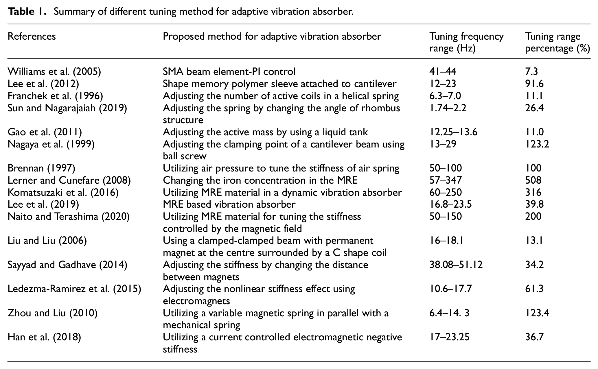
To overcome the tuning speed issue, some researchers have studied electromagnetic tuning methods for AVTA systems in active suspension and shock absorption applications. A Magneto-Rheological Elastomer (MRE) which can change stiffness by applying an external magnetic field has been used in different vibration absorbers (Komatsuzaki et al., 2016; Lee at al., 2019; Lerner and Cunefare, 2008; Li et al., 2014; Yu et al., 2020). MREs are fabricated from silicone gel and iron microparticles; using them changing the resonance frequency is rapid, controllable and reversible. However, the utilization of this unique material in vibration absorber proved to be challenging. In some implementations, the magnetic field generated by the excitation coil does not always create a predictable constant magnetic flux in the MRE device while the movable mass including the MRE and coil are moving relative to each other. Hence, the magnetic field created by the excitation coil is not effectively and efficiently imposed on the MRE (Naito and Terashima, 2020) . Li et al. (2020) proposed a novel MRE-based adaptive isolator with improved magnetic circuit model which accurately considers magnetic flux fringing.
A heavy-duty magnetorheological fluid mount (MRF) is implemented by Huang et al. (2021). The MRF mount has flow and squeeze operating modes utilizing both annular and radial MRF channels. A conical rubber part mounted between the mounts and the MRF valve provides base stiffness under static loads. In this system, the MR fluid can produce up to 48 kPa yield stress under the magnetic field of 1.0 T. The experimental results indicated that by adjusting the excitation coil current in the device, the effective stiffness can be increased by nearly 700%.
Some researchers presented alternative approaches to realizing magnetically controlled variable stiffness vibration absorbers. In the system proposed by Liu and Liu (2006), the device comprises a clamped-clamped aluminium beam, a permanent magnet which is mounted at the centre of the beam and a C-shaped electromagnet with poles on the both sides of the permanent magnet. In this device, the stiffness can be tuned instantaneously by varying the current in the electromagnet coil. Sayyad and Gadhave (2014) developed a variable stiffness vibration absorber mounted on a cantilever beam whose stiffness was adjusted by changing the distance between the magnets. Obtaining negative stiffness with a combination of electromagnets and permanent magnets was reported by Ledezma-Ramirez et al. (2015), Ledezma-Ramirez et al. (2012), and Zhou and Liu (2010), where changing an excitation current can adjust the negative stiffness. However, the permanent magnet’s characteristic is a function of temperature, and demagnetization can happen at high temperatures. Hence, such tuned vibration dampers may not be suitable for high-temperature applications.
As a solution to the temperature sensitivity issue for electromagnetically tuneable stiffness in vibration isolators, Han et al. (2018) proposed an electromagnetic asymmetric tooth structure wherein the absence of any permanent magnet material, the coil’s current can be adjusted to tune the stiffness of the system. In this design, the stator and the moving part are both made of electrical steel and have the same number of teeth, which are arranged symmetrically. When the current is applied to the coil, mounted around the stationary part, magnetic flux passes from one stator tooth to the opposite tooth on the moving part. When the oscillating part moves away from the equilibrium position in the vertical direction, an electromagnetic force is produced between the tooth pairs (proportional to the square of the coil’s current) to oppose the movement. This attraction occurs due to the cogging force effect, thus producing a mechanical spring effect which is electrically controllable.
This paper studies an alternative method for tuning the resonance frequency of a voice coil actuator (VCA) with a nonlinear spring by coupling it to a solenoid actuator (SA). It demonstrates another technique for attaining electromagnetically controllable stiffness and validates it through simulation analysis and experimental tests. Following this introduction, the construction of the ATVA is described and the theory of the vibration damper and dynamic model of the voice coil with a nonlinear spring used in this study is discussed in section 2. In section 3, the mathematical model and design constraints of the SA are explained. In this section, the geometrical parameters of the SA to address the design requirements and objectives are obtained through the sizing process, and the design of the SA is refined and verified using FEA analysis. In section 4, the performance of the full model of the ATVA is evaluated using FEA analysis. It is shown that in the case of a VCA with a nonlinear spring, applying current to the SA produces a tuneable negative stiffness and alters the overall resonance frequency of the actuator by controlling the equilibrium position and the operational range of the nonlinear stiffness of the VCA. Section 5 presents the results of experiments that were conducted to validate the proposed tuning method. Conclusions are drawn in the final section.
2. ATVA modelling
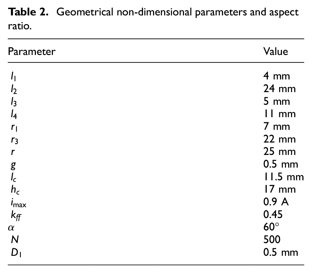
The ATVA system (Sharkh et al., 2022) is made by coupling the VCA to the SA, as illustrated by the solid model of an in-house designed system presented in Figure 1. In this design, the oscillating part of the VCA is directly connected to the SA’s plunger, using a brass, non-magnetic spacer and together compose the AVTA’s moving mass of 0.375 kg in total. The VCA is widely used in active vibration control systems (Banik and Gweon, 2007). When the coil is excited, the electric current interacts with the permanent magnetic field carried by the ferromagnetic circuit. It generates a Lorentz force vector perpendicular to the current and the magnetic field in the gap (Okyay et al., 2015). Powering the coil with an AC current generates a harmonic force that causes the proof mass to vibrate. In the designed ATVA, two ortho-planner springs are mounted on the top and the bottom of the VCA to mutually provide the stiffness for suspension of the proof mass. In this design, the permanent magnet together with the steel core, yoke, centre bolt and spacers, make up the moving part of the VCA. An aluminium heatsink is incorporated in the coil bobbin to conduct the coil resistive copper losses to the outside housing.
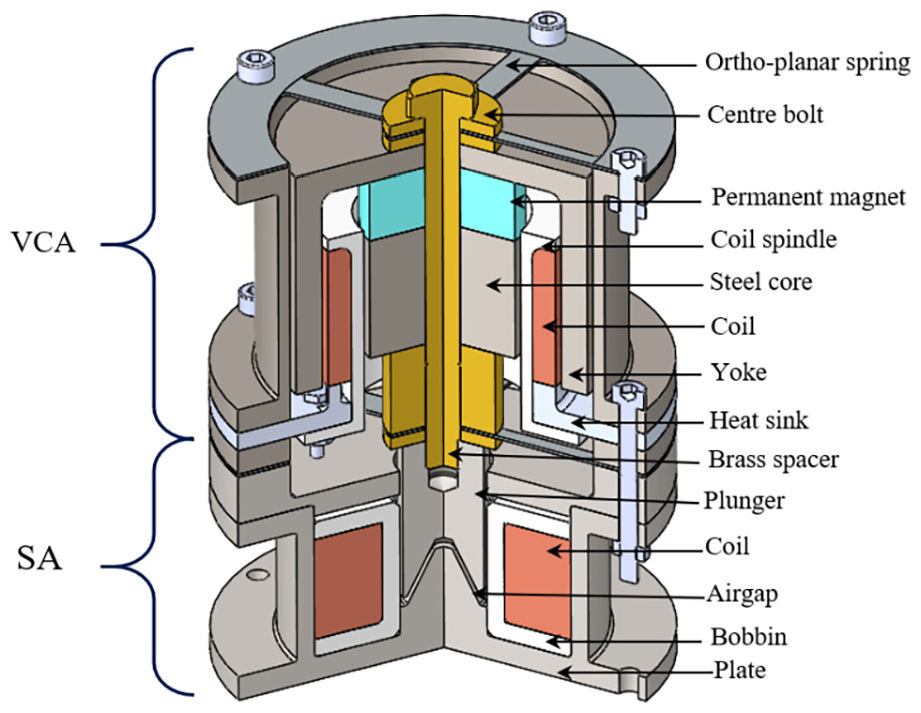
3D drawing of the designed ATVA.
In the SA, an electrical coil is wound around a ferromagnetic plunger (movable part). When electric current flows through the coil, a magnetic field is generated, and the plunger tries to move to minimize the reluctance (by closing the air gap). Therefore a mechanical pulling force between the plunger and SA’s plate is produced, which can be controlled by varying the current flowing through the SA’s coil (Gomis-Bellmunt and Campanile, 2010; Roters, 1941).
By supplying AC current to the VCA’s coil and DC current to the SA’s coil, ATVA moving part is subjected to two electromagnetic forces: a) a bidirectional oscillating force, that is,
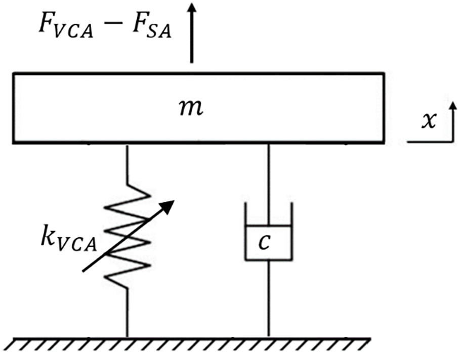
The schematic drawing for one axis active vibration isolation system.
The dynamic equation of ATVA can be written as

where x is the displacement from the moving mass’s equilibrium position, m is the proof mass, and
To characterize the spring stiffness of the VCA, different AC currents with amplitudes in the range of 0.1–1 A and the frequencies in the range of 20–100 Hz were applied to the VCA. The frequency responses were measured using a laser vibrometer and the displacement, acceleration and the force acting on the oscillating mass were calculated. By plotting the stiffness versus the displacement and conducting a curve fitting by setting the parameters to have the minimum mean-root-square of error, the nonlinear stiffness was determined. The results indicated that Othro-planner springs have a nonlinear stiffness. As shown in Figure 3, the stiffness of the VCA’s spring is displacement dependent. Hence, the restoring force contains products of the oscillating mass position determined according to Figure 3 and is a function of the equilibrium position of the ATVA and the operative range of application.
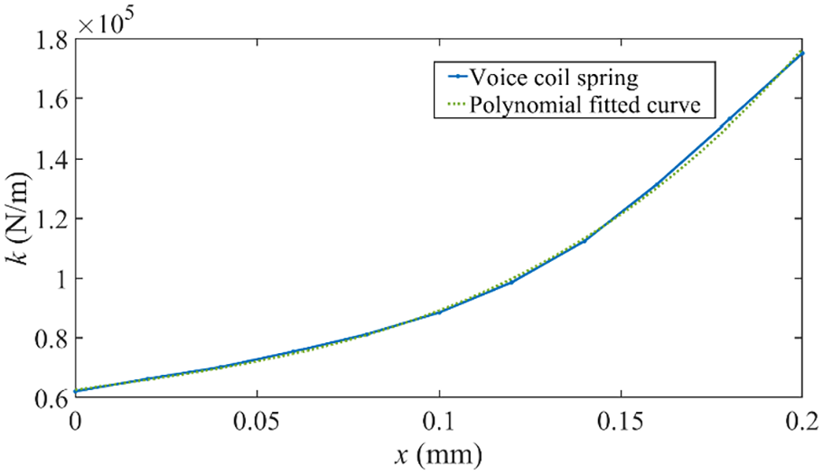
Spring stiffness versus extension length of the voice coil.
Curve fitting of the graph in Figure 3 results in

where the nonlinear stiffness coefficients are as follow: A = 1.02 × 10⁷
In the operating range of the device, the SA force-stroke characteristic changes as a function of the DC current supplied to the SA’s coil and the air gap between the plate and plunger of the SA. Hence, it acts as a preloaded negative electromagnetic spring and the force exerted by the SA on the moving mass can be written as

where
Hence, by adjusting the solenoid actuator’s current and the equilibrium position of the mass, both the spring stiffness and the solenoid electromagnetic stiffness can be changed to tune the resonance of the ATVA to the desired frequency.
3. Solenoid actuator
3.1. Geometrical modelling
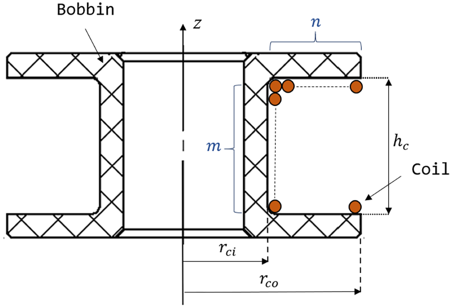
Studies show that compared with a flat plunger, a conical plunger type SA has a higher force over long stroke capabilities (Kumar et al., 2015). However, due to manufacturing limitations, in practice, a truncated conical plunger is normally used, as illustrated in Figure 4, which shows its main dimensional parameters. Nevertheless, to simplify the modelling and initial sizing process, an SA with a full conical plunger surface is assumed. Figure 5 shows the magnetic circuit of the SA model. The reluctance of the gap between two full conical surfaces is Roters (1941).
The geometry of the SA.
SA magnetic circuit simplified model with the conical plunger.
The other reluctances of the magnetic circuit are calculated as follow,
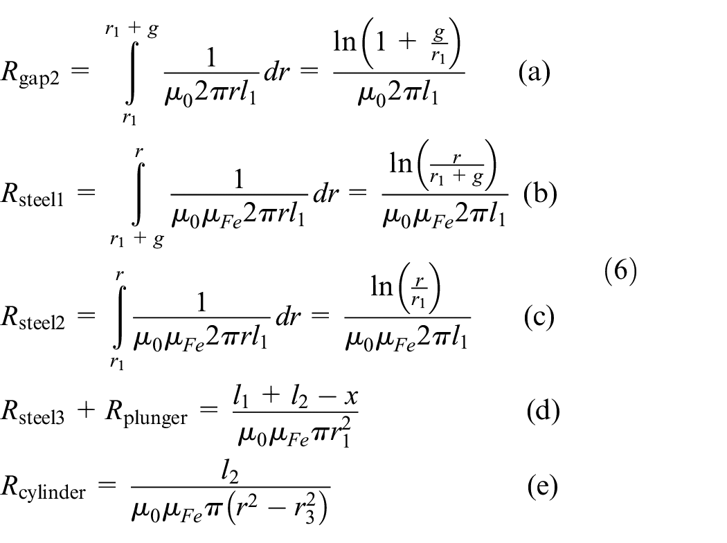
where,
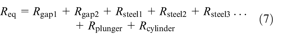
The magnetomotive force,

where
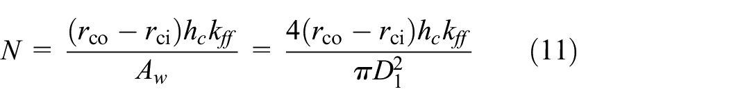
Another geometrical parameter of interest is the winding fill factor,
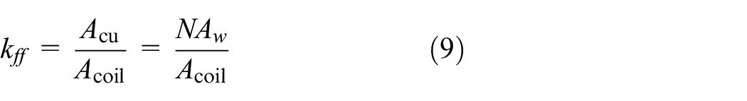
where
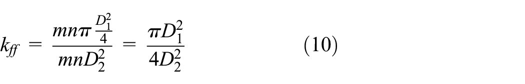
where
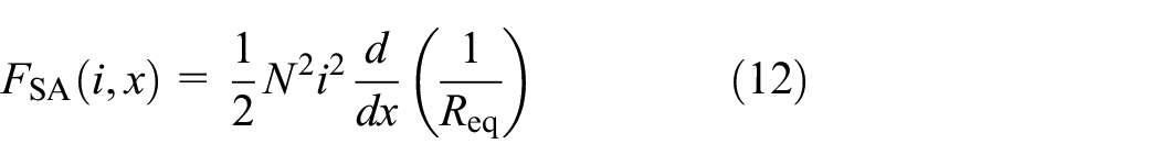
Also, it is possible to express the force acting on the plunger of the actuator as a function of the quantities of interest as (Fitzgerald et al., 2003)
SA coil cross-sectional area.
3.2. SA thermal modelling
Part of the electrical energy supplied to an electromechanical device is converted into heat, mainly in the coil. This thermal energy causes an increase in the coil’s temperature, which limits the device’s performance. Hence, obtaining the thermal model of the SA is critical to determining the device’s limits of performance. First of all, the resistance of SA’s coil is expressed as a function of copper resistivity and the geometrical dimensions as
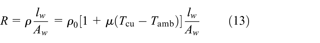
where
In the case of the SA heat is transferred by means of conduction from the coil to the inner steel yoke wall and by convection between the outer yoke wall and the surrounding environment. Note that for the purpose of simplifying the model, we assume a uniform temperature distribution within the coil. Figure 7 presents a scheme of the heat transfer model in the solenoid actuator. In the steady-state heating balance, the heat power produced in the coils due to the Joule effect, Q, equals with the power which the SA can dissipate through conduction and convection as
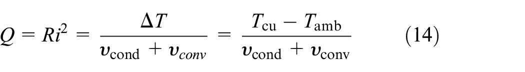
where
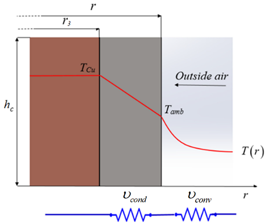
Heat transfer simplified model.
If the heat generated in the coil flows radially, the thermal resistances are as follow (Gomis-Bellmunt and Campanile, 2010)
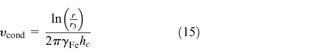
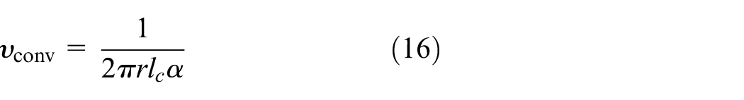
where
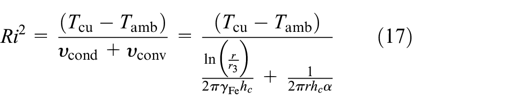
The maximum allowed operating temperature of the copper wire insulation is a constraint for the permitted operating temperature of the electromagnetic actuators. Exceeding the temperature limit can lead to drying of the insulation with a consequent short circuit between actuator’s coil conductors and the heatsink resulting in failure. From equations (13) to (17) with
3.3. SA analytical sizing
A numerical sizing process is carried out to determine the values for the set of geometrical parameters purpose, allowing for the maximum force acting on the plunger for a unit volume of the device. For this purpose, the objective function to be maximized has been identified as
(1) The aspect ratio, that is,
(2) Saturation must be avoided in all the components of the actuator. The magnetic flux density in steel made elements, that is, Bi = ϕ/Ai should be less than saturation limits T for AISI 1020 steel with
(3) To interface the SA with the manufactured VCA, a radius of
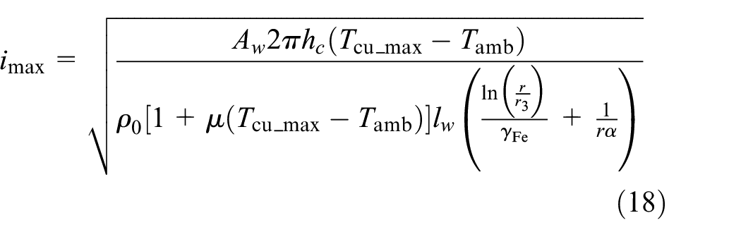
The rounded value of the design parameters obtained from the sizing process are shown in Table 2.
Geometrical non-dimensional parameters and aspect ratio.
A parametric 3D model of the SA has been implemented in Solidworks based on the optimized design of the device and practical manufacturing considerations. Figure 8 shows a 3D drawing of the designed SA. However, the above sizing method does not consider the effect of a truncated plunger, fringing and flux leakage. Hence, the FEA analysis was conducted to accurately analyse the performance of the designed SA.
3D drawing of the designed SA.
3.4. SA FEA
To verify the analytically designed SA, FEA analysis of the SA is carried out in ANSYS Maxwell®. The simulation offers more accurate results by numerically solving Maxwell’s equations which consider magnetic phenomena such as fringing and leakage flux. Furthermore, as the designed SA is cylindrical and symmetrical about the Z-axis, half of the model cross-section along the Z-axis is considered to speed up the simulation process. In this simulation, AISI 1020 Steel is the material assigned to the yoke and plunger. The B-H curve and the properties of this material can be found in (Gloria et al., 2009). Copper properties are assigned to the coil and to save the computation time, non-ferromagnetic and insulating components such as bobbin are not included in the model as their relevant properties, permeability and conductivity are similar to air. A ‘balloon’ boundary condition is assigned at the edge of the surrounding background region in ANSYS Maxwell to simulate infinitely large air surroundings. Note that the edge coincident with the vertical axis is not assigned to the ‘balloon’ since it is the axis of cylindrical symmetry. DC current excitation flowing through the cross-sectional surface of the coil is assigned. A force parameter is assigned to the plunger as an output variable to calculate the force acting on the moving component of the SA. Adaptive meshing is used with the maximum length of element is restricted to 1 mm for the SA’s components and a maximum error of 0.1%. For four different air gap sizes and DC current values applied to the coil, Figure 9 presents the magnetic flux lines flow and the magnetic flux density on the parts of the designed SA.
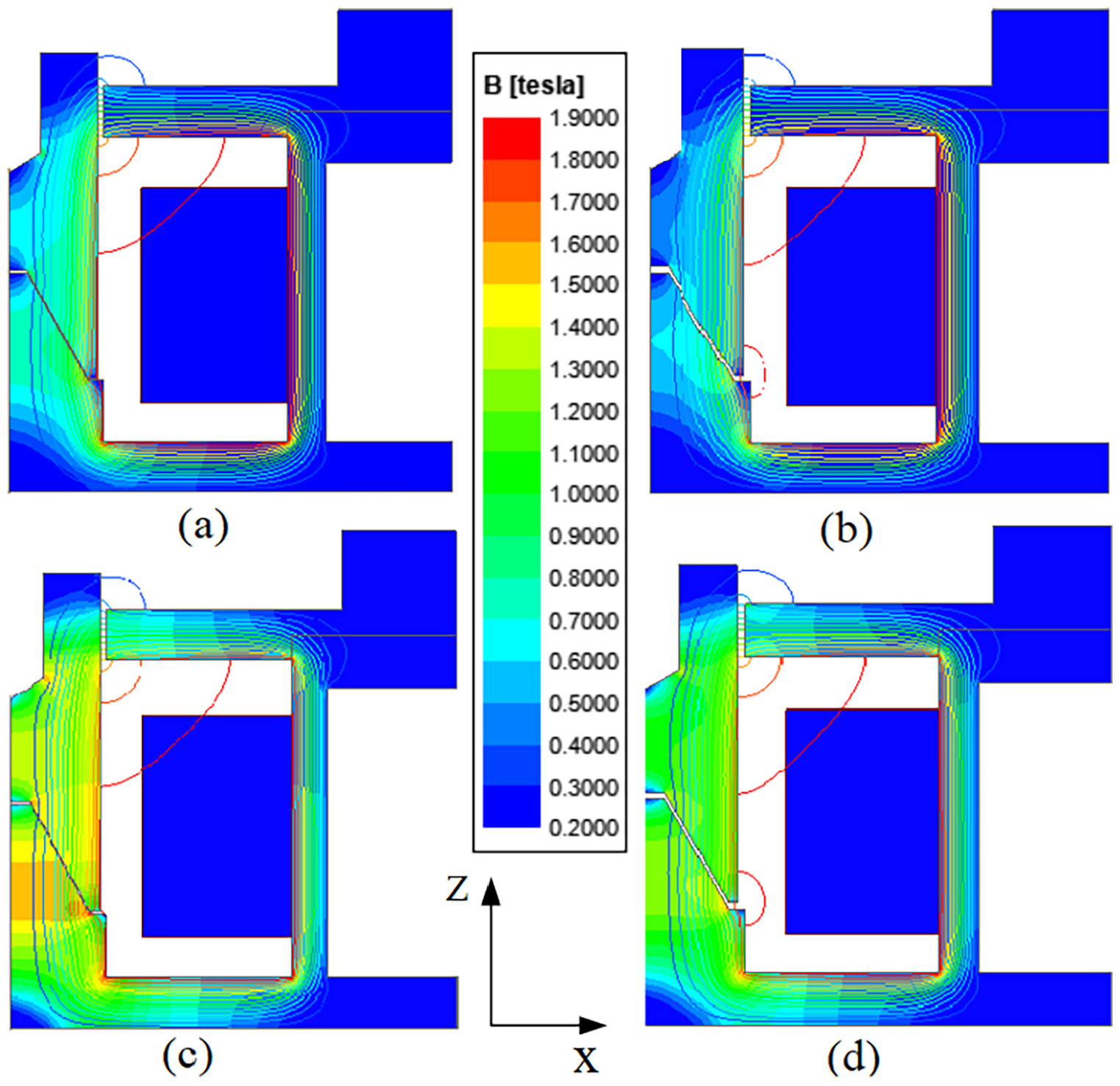
SA magnetic flux lines and flux density at: (a)
It is seen that the magnetic flux is mostly confined in the ferromagnetic circuits formed by the plunger, backplate and yoke of the device with the observation of some magnetic leakage flux in the vicinity of the air gap areas. Since the effect of fringing increases with the air gap length, the secondary air gap length is kept as low as possible during the SA design according to the tolerance required to avoid sliding contacts between plunger and yoke. In simplified models of electromechanical actuators, the effect of this phenomenon is usually neglected. However, FEA analysis accounts for these effects providing a more accurate result.
Comparing the four scenarios shown above indicates that by enlarging the air gap in the Z direction, the flux leakage around the air gap is decreased due to the increase of total reluctance in the magnetic circuit. Also, by changing the DC current in the coil and the air gap distance, the magnetic flux density in the air gap is also altered.
According to equation (12), the plunger’s force is a function of the total reluctance of the magnetic circuit and the coil’s current. However, based on equations (5) and (7), the total reluctance of the SA varies as a function of the air gap distance (stroke). Figure 10 presents the SA’s force-stroke characteristics for different values of the coil’s current. As expected, by increasing the coil’s current, the applied force on the plunger increases; however, increasing the stroke’s amplitude, the plunger force is reduced. The local slope of the tangent line to the force-stroke graph shown in Figure 10 is the electromagnetic stiffness induced by the SA,
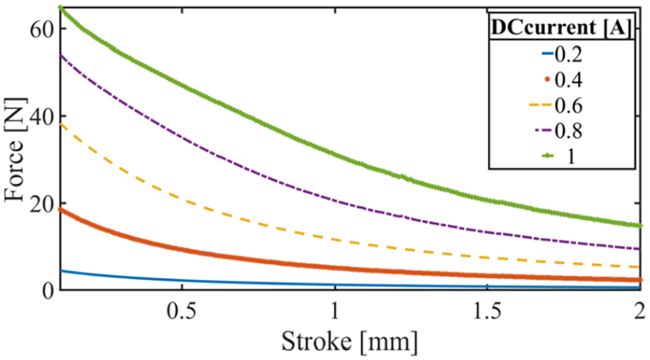
SA force-stroke relation obtained from FEA analysis for the parameters shown in Table 1.
4. ATVA FEA analysis
Figure 11(a) presents FEA simulation results of the flux lines and magnetic flux density through the AVTA when a DC current of 1 A and no current is applied to the VCA coil. The VCA has a coil with 34 turns of a wire with 1.02 mm diameter. Figure 11(b) shows the flux line when 1 A DC in supplied to the SA’s coil and 1 A also is supplied to the VCA’s coil. In this simulation the FEA setting and materials are the same as those were used for the SA simulation. The magnet material is NdFe BN42. There is minimal flux leakage between the SA and the VCA, and hence, the magnetic fields in the two actuators remains decoupled and the magnetic flux circuit of both systems can be assumed to be independent from each other. Hence, the VCA and the SA can be controlled independently by applying AC current to the VCA to control the amplitude of oscillation and DC current to the coil to alter the magnetic stiffness of the AVTA.
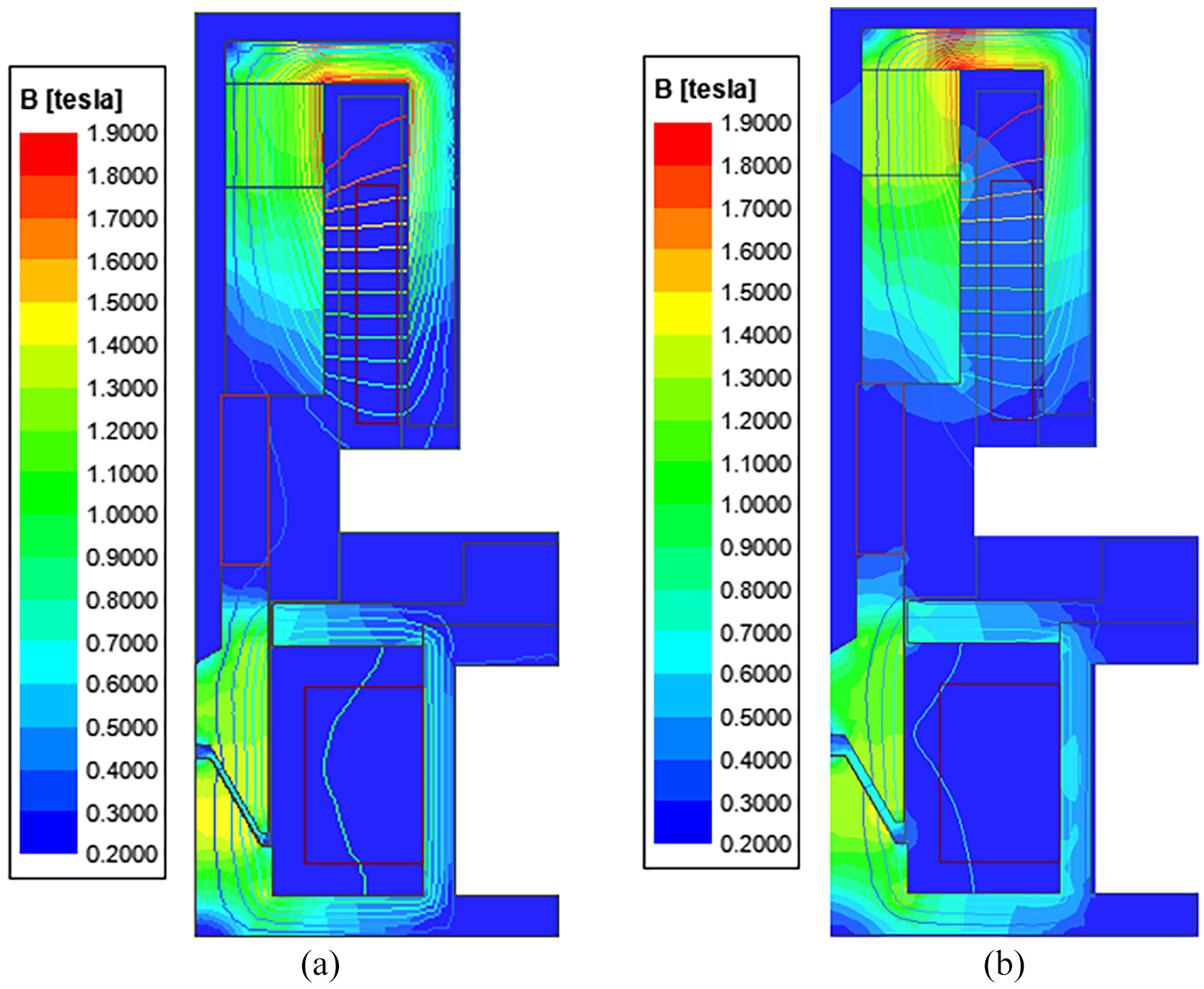
FEA analysis of the ATVA (a) when 0 A to the VCA and 1 A DC to the SA are supplied, (b) when 1 A AC to the VCA and 1 A DC to the SA are supplied.
Figure 12 shows the frequency response of the ATVA for different values of the DC current injected to SA’s coil when the VCA is excited with 1 A at different frequencies. It is seen that in the absence of any DC current in SA, the actuator has a resonance frequency of 66 Hz. However, by increasing the DC current in the coil, two different factors contribute to the resonance frequency change. The first is the change of the force-stroke characteristics of the SA according to Figure 10 and applying a negative stiffness to the dynamic system. The second is the change of the equilibrium position of the moving mass due to the increase of pulling force in the SA air gap and hence altering the operational range of the stiffness-stroke curve of the VCA according to Figure 3 and thus changing the nonlinear mechanical spring of the AVTA. Figure 13 illustrates the mass displacement in the steady-state for two cases with the SA’s DC current of 0 and 1 A, when both systems are driven at 80 Hz. It is seen that when injecting 1 A into the SA’s coil, the equilibrium point of the system is shifted down by 0.06 mm, which, according to Figure 3, results in a higher mechanical stiffness to the oscillating mass.
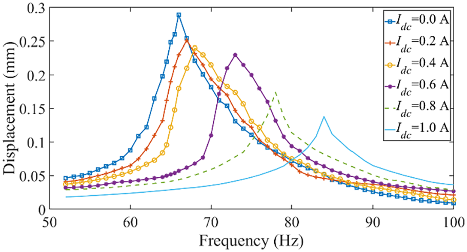
ATVA frequency response obtained from FEA.
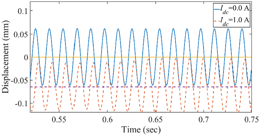
Displacement of the ATVA moving part versus time for two different currents applied to SA’s coil when the VCA is excited at 80 Hz.
The above two factors jointly determine the main resonance frequency of ATVA, as shown in equation (4). For the designed AVTA, it is seen that despite the amplification of the negative magnetic stiffness by increasing the DC current in the coil, due to the change of the equilibrium position of the ATVA, the positive mechanical stiffness of the VCA is increased significantly. Hence the effective applied stiffness to the dynamic structure is boosted, which causes the increase of the resonance frequency of the AVTA. For instance, as it is seen in Figure 12, by injecting 1 A DC current into the SA, the resonance frequency is changed from 66 Hz to around 84 Hz.
5. Experimental implementation
To validate the theoretical calculations, a demonstrator of the device was manufactured and tested. First, the SA is assembled and mechanically connected to the VCA by screwing an adapter flanges on the VCA and the SA sides. Also, Loctite® thread-locking fluid is used to prevent the plunger from becoming loose due to the vibrations acting on the moving mass and eliminating backlashes between the components. Figure 14 shows the assembled ATVA, rigidly mounted on a steel plate and secured to an anti-vibration base platform. The 500 turns VCA’s coil (0.5 mm wire) is wound, using a manual winding machine, around a Derlin bobbin.
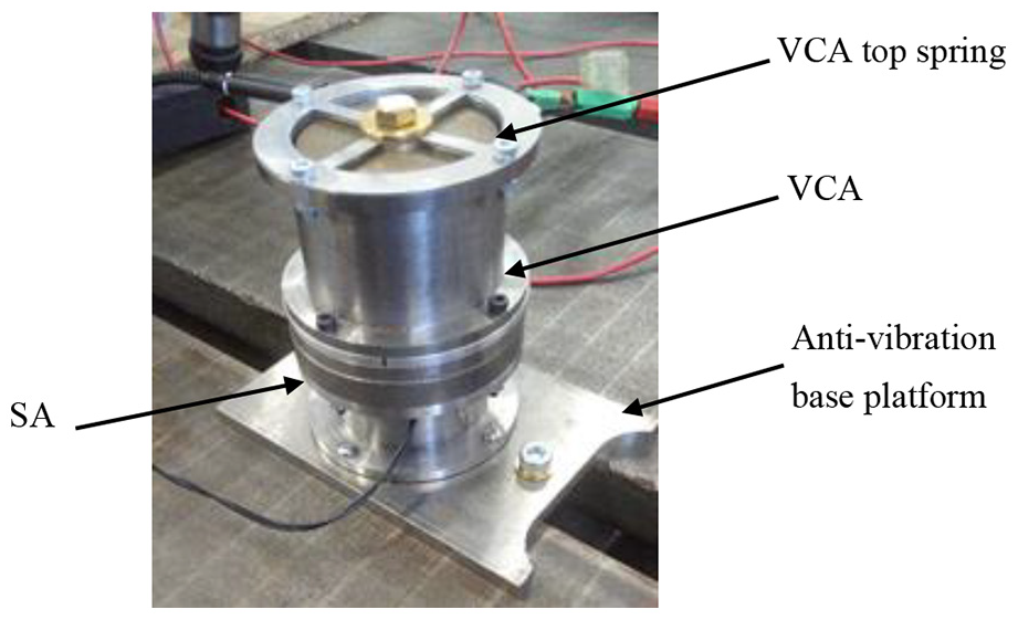
The manufactured AVTA on the test bench.
Figure 15 shows the schematic of the experimental setup used to test the manufactured ATVA. The VCA actuator is powered with an AC current supplied by a function generator model Aim TTiTG315, capable of signal generation with an operative frequency range from 0.03 Hz to 3 MHz. A power amplifier (TPA-50) is connected to the function generator to increase the output power, mainly to allow higher current flowing in VCA’s coil to achieve higher reaction forces. A DC laboratory power supply (EA-PS 2042) is used to power the SA’s coil. To prevent damages to the power source and the SA, the values of overcurrent and overvoltage protection of the device are set accordingly to a maximum permissible values of 14 V and 3 A, respectively. Also, the ATVA’s moving mass’s vibration velocity is measured using a Portable Digital Vibrometer (PDV) installed on the top of the VCA. The laser vibrometer was pointed on the top of the surface of the moving body (oscillating mass), pointing to a screw coated with a special reflective film. To calculate the displacement and the acceleration of the moving mass, the measured velocity by the vibrometer is numerically integrated and differentiated, respectively. The force on the active mass is calculated by multiplying the mass by the acceleration. To obtain the mechanical (displacement, velocity, acceleration) frequency responses of the device, the ATVA is tested over a vibration frequency range sweeping from 5 to 130 Hz for different values of the SA’s DC input current. The vibration frequency was set by setting the frequency of the signal supplied by the function generator. The coil applied voltage and current waveforms were monitored using an oscilloscope to ensure that the waveforms remain in the linear range of the amplifier and quantify the performance of the device.
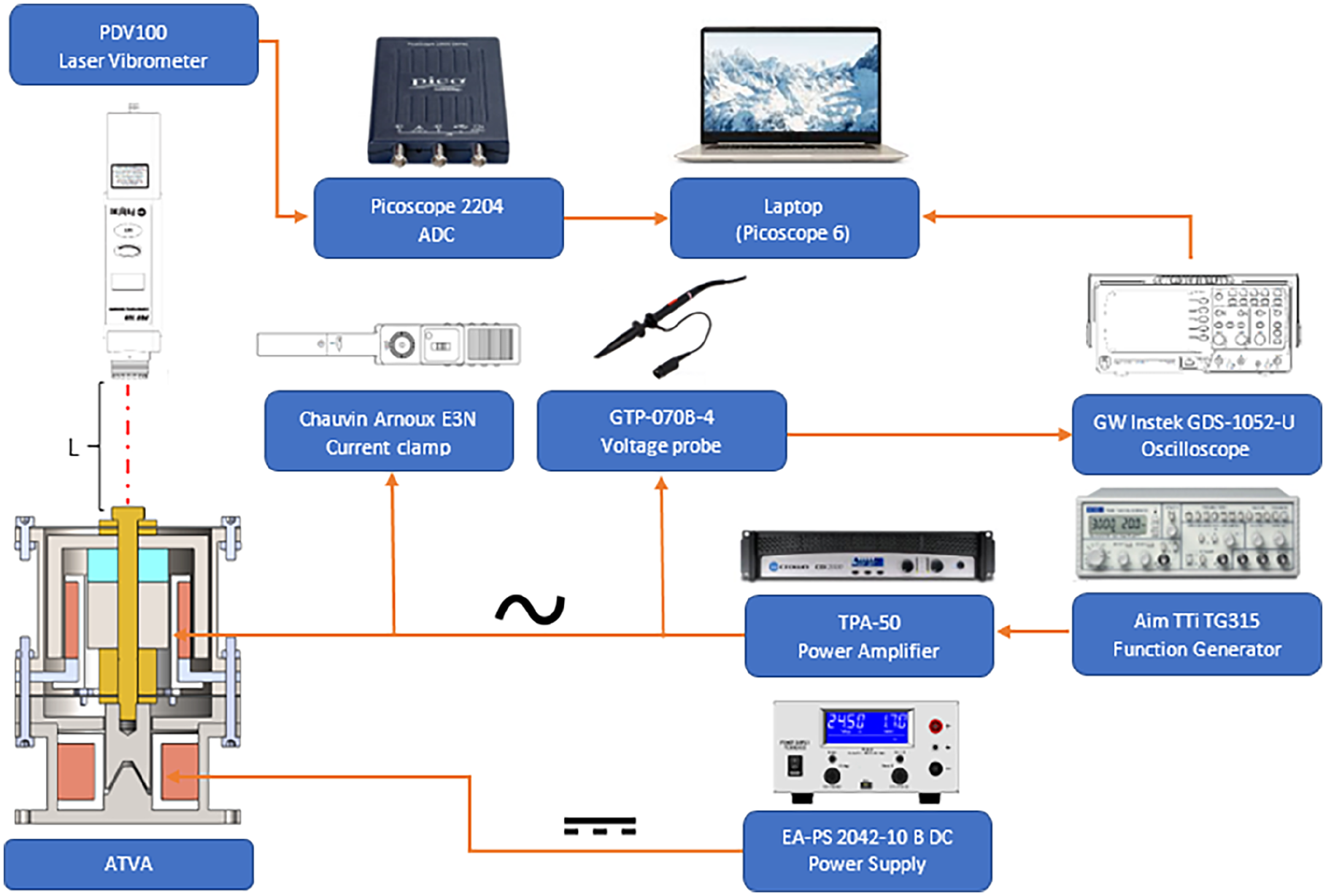
Schematic of the experimental setup used to test the manufactured ATVA.
6. Results and discussion
Figure 16 shows the frequency response of the ATVA for the displacement, velocity, acceleration and the force of the moving mass. It is seen that the resonance frequency of the device in the absence of any DC current in the SA’s coil is around 67 Hz which is equivalent to an actuator with linear spring stiffness of 66457 N/m. However, by increasing the SA’s coil current, as it was expected from FEA simulation, resonance is shifted to higher frequencies.
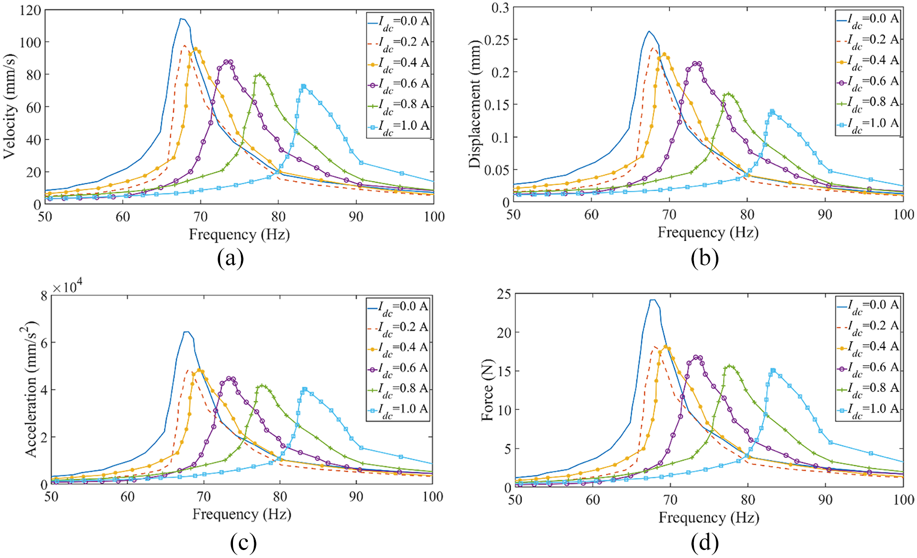
AVTA frequency response obtained from the experiment: (a) displacement, (b) velocity, (c) acceleration, and (d) force.
This behaviour is mainly attributed to the nonlinear characteristic of the VCA spring, as discussed earlier. The SA electromagnetic spring has negative stiffness which decreases the overall stiffness of the device. However, the SA’s pulling force varies the equilibrium point of the moving mass and the working range of the suspension system; this results in an increase in the effective mechanical stiffness which represents the dominant stiffness term. The frequency response is skewed to the right due to the nonlinearity of the system. With 1 A DC SA current, the resonance frequency is around 83 Hz which is close to the FEA prediction of the resonance frequency, as it is seen in the comparison graphs shown in Figure 17. When applying 1 A DC to the SA coil, the equivalent linear spring stiffness of the ATVA is around 101990 N/m which shows a more than 55% increase in the effective spring stiffness of the system in comparison with the case with no DC current on the SA’s coil.
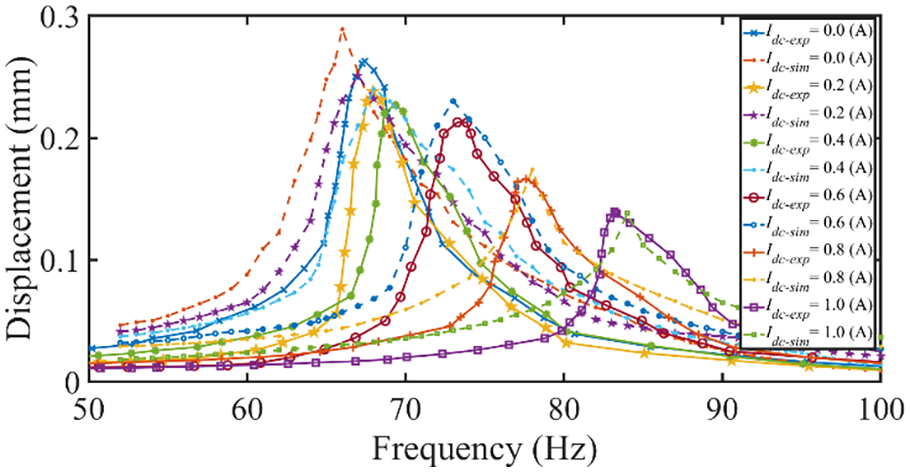
Comparing FEA analysis versus experimental results of the AVTA displacement for different DC current values.
The experimental results demonstrate that by changing the resonance frequency of the ATVA, it is possible to increase the exerted force at frequencies higher than the initial resonance frequency. For instance, it is evident that for the case of the ATVA without any DC current, the exerted force at the frequency of 83 Hz is around 3.7 N. However, by tuning the resonance frequency of the ATVA, by controlling the DC current supplied to the SA’coil, the exerted force can be increased to 15 N at 83 Hz, which shows more than 305% increase on the force which is a significant improvement that can be utilized in a wider range of applications including active vibration control systems. In this case, the resonance frequency of the ATVA has been increased from 67 to 83 Hz, which indicates a 23% change in the resonance frequency.
Due to the variation of applications and tuning methodologies, a direct comparison between the result of this study and other proposed solutions in the literature for extending the dynamic range of an actuator is not possible. However, a relatively similar percentage change in the resonance frequency of an electromagnetic actuator is presented by Han et al. (2018) which showed that by tuning a variable negative stiffness, the resonance frequency of an asymmetric tooth actuator has been decreased from 23.25 to 17 Hz (26.8% reduction), when the control current is changed from 0 to 0.8 A. In that actuator applying the negative stiffness cause the reduction of the resonance frequency of the structure; however, for the presented AVTA in this paper, the tuning mechanism is designed to increase the resonance frequency of the actuator.
Although in theory, the exerted force by the VCA can be amplified by increasing the excitation current, in practice, the amount of applied current to the VCA should not exceed the maximum allowable limit. This constraint is determined by the insulation and thermal characteristics of the VCA. For instance, in the case of the AVTA and in the absence of using the tuning mechanism, producing 15 N of force at 83 Hz requires injecting a current of 4.05 A (assuming the linear relation between force and current); however, considering that will not be feasible as the maximum permissible current is 1 A. Using adaptive tuning of resonance, it is possible to increase the force considerably without exceeding the VCA current rating, which improves the effectiveness of the device in active vibration control applications.
7. Conclusion
This paper investigates the performance of an SA in tuning the frequency response profile of an ATVA with nonlinear spring stiffness. For this purpose, an SA is directly coupled to a VCA with nonlinear spring stiffness such that the moving part of the VCA and oscillating part of the SA jointly comprise the moving mass of the ATVA. The SA imposes a force on the moving mass of the ATVA, proportional to the SA’coil current and varies with the oscillating mass position (in other words, the force is a function of SA’s coil current and air gap). This force is amplified by increasing the DC current on the SA’s coil and is attenuated by increasing the SA’s air gap. As the exerted force by the DC current is a function of the moving mass displacement and is reduced by increasing the SA’s air gap, it acts as a tuneable negative stiffness. It can be adjusted to affect the overall device spring stiffness and tune the ATVA’s resonance frequency. In addition to the produced negative electromagnetic spring stiffness, the pulling force on the SA’s air gap changes the equilibrium point of the ATVA and hence the operating range of the nonlinear mechanical suspension spring. For the VCA used in this study, changing the equilibrium of the operation zone, the effective nonlinear mechanical spring stiffness is altered. The combination of the VCA’s stiffness and the electromagnetic stiffness imposed by the SA composes an overall effective ATVA’s stiffness that determines the system’s resonance frequency.
Several aspects of the designed AVTA deserve further study. Unlike some other approaches presented in the literature for tuning the resonance frequency of an oscillating structure, such as the methods presented in Table 1, the demonstrated AVTA can adjust its stiffness instantaneously. However, further research is needed to investigate the transient effect of stiffness changing on the dynamic response of the structure. Also, as discussed above, the focus of this paper is to demonstrate the feasibility of extending the dynamic range of a given VCA. However, it remains an objective of future work to develop the design procedure of the AVTA as a united system, to design of the VCA in conjunction with the design of the SA. In that case, in addition to the extension of the dynamic range, minimization of energy consumption for the AVTA can be a design optimization goal. Also, similar to the electromagnetic vibration absorber presented in by Liu and Liu (2006), the AVTA does not require any mechanical drive system for the tuning mechanism. Hence, it can be a good candidate for miniaturization and can be implemented in micro-electro-mechanical (MEMS) devices.
Footnotes
Declaration of conflicting interests
The authors declared no potential conflicts of interest with respect to the research, authorship, and/or publication of this article.
Funding
The authors disclosed receipt of the following financial support for the research, authorship, and/or publication of this article: This work was supported by the Intelligent Structures for Low Noise Environments (ISLNE) EPSRC Prosperity Partnership (EP/S03661X/1).