
Abstract
The turbulent fluid flow and convective heat transfer in counter-rotating disk cavity with central axial air inflow and radial air outflow are numerically studied based on the finite volume method. Efforts are focused upon the influence of the rotation number Rt on the flow structure, cooling performance, sealing effect, and surface tangential friction characteristics in the cavity. The stagnation point where the radial outward flow along the upstream disk driven by the rotation force meets the radial outward flow along downstream disk driven by the combination of rotation force and inflow inertial force moves from upstream disk wall to the shroud with increasing Rt. At the Rt far smaller than 1, the fluids in the core region between two disks rotate with the upstream disk like a rigid body, and the tangential velocity of the rotating core decreases with the increase of the disk cavity radius, which is different from the Batchelor-type flow. At the Rt larger than 1, the fluids on the upstream disk side rotate like the Batchelor-type flow, while the sandwich rotation disappears in the fluid on the downstream disk side. The temperature on the upstream disk wall increases and then decreases with increasing values of Rt, and the critical value of Rt for the change of temperature variation is assessed to be at about Rt = 0.69. The temperature and radial temperature gradient of the downstream disk wall decrease with increasing Rt. With increasing Rt by increasing the disk rotation rate, the pressures near the downstream disk decrease, while the frictional moments on rotating disks increase. Due to the effect of flow structure, the frictional moment on the upstream disk is smaller than that on the downstream disk.
Introduction
As the key component of the aero engine, the turbine disk has a great influence on the safe operation of the aero engine. To achieve large thrust and high thermal efficiencies, high temperatures are required in the turbine stage of a modern gas turbine engine. Therefore, superposed flow of air is used to cool the turbine disks to ensure the extended life of them. 1 In addition to providing cooling, the air supplied from the compressor serves as a seal that prevents hot gas from being ingested into the cavity between the turbine disks. 2 Air ingestion is affected by the pressure distribution inside the cavity, which is dependent on the velocity distribution. 3 In this way, optimizing disk cooling efficiency and disk cavity sealing performance requires profound insight into the inherent flow circulation and the heat transfer characteristics in the disk cavity.4,5
Turbine disk cavities can be classified into three different modes of configurations: (1) rotor–stator disk cavity modes (one disk stationary and the other one rotating at some rate), (2) co-rotating disk cavity modes (two disks rotating in the same senses), and (3) counter-rotating disk cavity modes (two disks rotating in opposite senses). The flow in rotor–stator cavity was investigated experimentally and numerically by many researchers, such as Séverac et al., 6 Séverac and Serre, 7 and Tuliszka-Sznitko et al. 8 The non-isothermal cavity conditions were also taken into account in many investigations. Poncet and Schiestel 9 performed detailed computations using the differential Reynolds stress model (RSM model) for the rotor–stator cavity with superposed axial inflow and outflow. Tuliszka-Sznitko and Majchrowski 10 performed numerical studies on the non-isothermal flow in the rotor–stator cavity, presenting distributions of the local convective heat transfer coefficient along the stator and rotor for different aspect ratios and Reynolds numbers. Tuliszka-Sznitko et al. 11 investigated the unsteady and turbulent non-isothermal flows in a rotor–stator cavity and discussed the influence of the aspect ratio and Reynolds number on the flow structure and heat transfer characteristics. Harmand et al. 12 delivered a review of the main research results for the fluid flow and convective heat transfer in rotor–stator configurations with and without impinging single jets, as well as multiple jets.
As to the co-rotating disk cavity configurations, the flow and heat transfer characteristics have also been studied extensively, and numerous papers on the corresponding subjects have been published in the recent years. For example, Soong et al. 13 employed smoke as the tracer for visualizing the three-dimensional swirling flows between two co-axial disks rotating at various conditions and explored the effects of the shroud on disk rim and the gap size between the two disks on the development of swirling/vortical flow structure in rotating disk systems. Gauthier et al. 14 studied experimentally the flow characteristics inside the co-rotating disks cavity system enclosed by a rotating shroud attached to the faster disk and reported three different kinds of instability patterns. Wu 15 investigated the flow structure between enclosed co-rotating disks using particle image velocimetry with polycrystalline particles and described eight subflow regions. Huang and Hsieh 16 experimentally studied the flow features in the axial midplane between the two shrouded co-rotating disks using the flow-visualization method assisted by the laser particle–laden and particle image velocimetry method. In their experimental work, five characteristic regions were identified according to the flow velocity distribution features in the interdisk midplane. Soong 17 investigated the fluid flow and heat transfer between two co-axial disks rotating independently and explored the convective heat transfer mechanisms involved in the two-disk flows at various rotation and configuration conditions. However, from the open literature report, it is found that most of the surveys on the flow and heat transfer inside the co-rotation disks cavity are associated with the relevant topic in the closed rotating disk cavities. As to the co-rotating turbine disk cavities with the superposed flow, little work has been done on the flow structure and heat transfer characteristics.
As the advanced turbine technique, counter-rotating turbine can provide higher aerodynamic efficiency and smaller weight and size of the engine. They may also reduce the gyroscopic moment produced during maneuvering flight. 18 Interest in the flow between counter-rotating disks is increasing. Poncet et al. 19 investigated numerically the turbulent Von Kármán flow between the two shrouded counter-rotating disks based on the RSM model and analyzed the influences of the aspect ratio of the cavity, the rotational Reynolds number, and the rotating disk speed ratio and the influences of the presence or absence of impellers on the dynamics and the turbulence properties in the Von Kármán configuration. Tao 20 conducted an unsteady three-dimensional direct numerical simulation to investigate flows between the two counter-rotating co-axial disks which are called the “Open Von Kármán Swirling Flow.” As mentioned above, several studies have been carried out with the objective to get a precise knowledge of air flow structures in the counter-rotating disk cavities up to now. Nevertheless, to the best of the authors’ knowledge, very little survey on the heat transfer and sealing effects in the non-isothermal counter-rotating disk cavities can be dated, 4 and there is also no report about the flow structures and heat transfer characteristics in the counter-rotating disk cavity system with air inflow and outflow. With the cooling air supply, the rotation forces and the inflow inertial force interact and compete with each other, which makes the mixing flow and heat transfer characteristics become more complex.21,22 To describe the complex competition effects of rotation forces and inflow inertial force on the rotating disk cavities, a non-dimensional characteristic parameter, the rotation number Rt is defined as Rt = Rew/Re, 23 where Rew is the disk rotation Reynolds number, while Re is the axial inflow Reynolds numbers. The principal parameter Rt links the effects of both the rotation and inertia of the axial inflow. In this article, the turbulent fluid flow and convective heat transfer in counter-rotating disk cavities with the central axial air inflow and radial air outflow are numerically studied, and the effects of the principal parameter Rt on the flow structure, sealing, and cooling performance are explored with the theory of rotating fluids. It is expected that the numerical research results could provide better insights for understanding complex mechanisms of the three-dimensional rotating flows and heat transfer in counter-rotating disk systems with superposed flow.
Physical system and numerical approach
Physical system
Figure 1 shows the coordinate and physical system adopted in the present numerical simulation. The counter-rotating disk cavity system consists of two disks (upstream disk 1 and downstream disk 2 separated by a spacing of s = 68 mm), with thickness δ = 30 mm and diameter 2r0 = 400 mm, and a cylindrical shroud attached on the rim of upstream disk 1. A small clearance, sc = 3.5 mm, separates the shroud and disk 2 allowing disk 1/shroud set and disk 2 to rotate independently. The cooling air enters the cavity from the central opening (with diameter 2rin = 50 mm) of the upstream disk at a mass flow rate ṁ and leaves radially through the small clearance between the shroud and disk 2 at the position of r = r0. The disk 1/shroud set is held to rotate at speed Ω1, and disk 2 is held to rotate in the opposite direction at a same speed Ω2. The circumferential outer surface of each disk is heated by an 800-W heater. Other outer surfaces of the cavity are assumed to represent adiabatic boundaries. The rotation Reynolds number is defined as Rew = Ω1r02/v, and the axial inflow Reynolds numbers is defined as Re = v0r0/v, where v denotes the kinematic viscosity of the fluid and v0 denotes the superimposed flow velocity calculated as v0 = ṁ/(ρπrin2). For the data here, the rotation number Rt, which describes the complex competition effects of rotation forces and inflow inertial force on the turbulent flow in the rotating disk cavity, can be varied in the range of 0.091–1.81 by changing the coolant flow rate and/or the disk rotation rate.

Schematic of the coordinate and rotating disk cavity system.
Numerical approach
Governing equations
With assumptions of incompressible and steady-state flow in the rotating disk cavity, the Reynolds-average Navier–Stokes (RANS) continuity equation, momentum equation, and energy equation written with cylindrical variables (r, z, and ϕ) in a rotating frame of reference are given by the following relations, respectively 17


where
In equation (2), the rotational forces can be expressed as


where the centrifugal force is proportional to the square of the angular velocity and the radial position of the fluid cell and lies in radially outward direction and the Coriolis force couples the radial component 2ρΩVφer and tangential component −2ρΩVreφ. Both are proportional to the angular velocity Ω and local linear velocities.
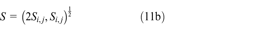
With the geometric and rotational parameter, the rotation Reynolds number used in the present calculation lies in the range of 6 × 10⁴ < Rew < 4 × 10⁶, which means that the flow in the core region between the two counter-rotating disks is turbulent. 18 The turbulence models employed for computation is the RSM model and the Reynolds stresses are related to the corresponding mean rates of strain through an isotropic eddy viscosity µt

The renormalization group (RNG) k-ε turbulence model is used to calculate the turbulent viscosity μt, in which μt is related to the turbulent kinetic energy k, and its rate of dissipation ε, by

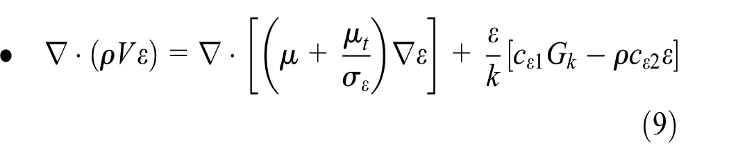
and k and ε are obtained from the transport equations

The coefficient cε1 of the rate of production of turbulence kinetic energy Gk is calculated as 22


and cε2, σk, σε, and cµ are constants


The wall-function approach is employed to calculate the wall-proximity effects for the flow in the near-wall regions. 24
Boundary conditions
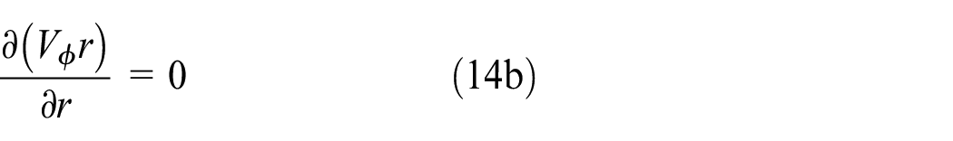
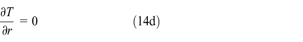
For the inlet, a uniform velocity and temperature condition was defined, and the full-developed outlet boundary condition was defined at the outlet. No-slip conditions were used on the walls


Numerical algorithm and its reliability
As the disks with thickness δ are included in the calculation domain, the calculation for the fluid and solid conjugate heat transfer is established. The fundamental equations are solved using the finite volume (FV) method. Discretized equations are formed on a collocated grid using the SIMPLE algorithm for correction of the pressure. The scheme of difference approximations for the convective term is quadratic upwind interpolation, and the second-order upwind difference approximation is applied to the diffusion terms. A grid with equidistant nodes was used everywhere, except near the solid surfaces, and the grid node number is 36188. The measure employed to judge convergence of the solution is that the normalized absolute residual sum of the control volumes is less than 10−4. The sensitivity of the grids was analyzed, and increasing the radial and axial nodes by the factor of 1.3 and 1.45, respectively, increased the maximum variation of the effective turbulent viscosity by 0.5%.
To provide a benchmark for the numerical approach used in this study, an experimental model done by Xu et al. 25 was employed to calculate, and the results were compared in Figure 2 for the two cases of the mass flow rate. For the rotor–stator disk cavity with central axial air inflow and heated rotating disks, the calculated radial temperature profiles on the rotating disk wall are in reasonable agreement with those measured in the experiments. The results of numerical calculation for the other four mass flow rates (i.e. ṁ = 249, 299, 348, and 448 kg h−1) are also in good agreement with the experimental results. So, the steady calculation can resolve the important flow and heat transfer features inside the rotating cavity with central axial air inflow.

Comparison of the calculated temperature distributions on the rotating disk wall with the measured ones: (a) ṁ = 200 kg h−1 and (b) ṁ = 405 kg h−1.
Results and discussions
Flow structures in the counter-rotating disk cavities with axial inflow and radial outflow at different rotation number Rt
Figure 3 presents the meridional distribution of stream functionΨ and tangential velocity Vφ in the counter-rotating disk cavity for Rt = 0.091. The cooling air flows axially into the cavity and flows radially outward along the downstream disk under the coupled action of the rotation force and inertial force. In the case of Rt = 0.091, that is, the rotation Reynolds number is much smaller than the inflow Reynolds number, the intensity of the radial outflow driven by the rotation force along the upstream disk is much weaker than that driven mainly by the inertial force along the downstream disk. So, the radial outflow along the downstream disk turns to the upstream disk when arriving at the shroud and flows radially inward along the upstream disk. As a consequence, the radially inward flow along the upstream disk meets the centrifugally driven (radially outward) flow at the stagnation point at some radius rst on the upstream disk wall and then flows axially to the downstream disk as the confluence. Consequently, a stronger counterclockwise recirculating secondary flow and a weaker clockwise recirculating secondary flow separated by the stagnation streamline originating from the stagnation point are formed in the r–z plane as is shown in Figure 3(a).

Contours of (a) stream function
From Figure 3(b), it can be seen that the tangential velocity remains almost constant in the core region for a fixed radial position and decreases with increasing radius. The fact means that the fluids in the core region between the two disks rotate at some rate with the upstream disk like a rigid body, and the rotating speed of the rotating core decreases with increasing radius. Obviously, the flow is neither Batchelor-type flow (with angular speed of the rotating core increasing with radial distance) 26 nor Stewartson flow (with tangential velocity varying almost linearly in the axial direction), 27 and it is a new type of flow. The complex formation mechanism of this new type of flow structure is explained in the previous work. 22
In Figure 4, the meridional distribution of stream functionΨ and tangential velocity Vφ in the counter-rotating disk cavity for Rt = 0.725 is presented. At this rotation number Rt with an increased rotation Reynolds number Rew, the centrifugally radial forces are enhanced. Besides, the inflow inertial force is weakened because part of energy of the impinging jet is released at the disk cavity outlet. Thus, the radially outward flow can resist the radially inward impinging jet along the upstream disk. As a result, the stagnation point at which two streams meet migrates to the shroud, and the clockwise recirculation expands outward to the shroud, while the counterclockwise circulation becomes smaller, as can be seen from Figure 4(a).

Contours of (a) stream function
With the positive Vr1 and Ω1 in the boundary layer of the upstream disk wall, the tangential component of Coriolis force −2ρΩ1Vr1 becomes negative, and it drives the fluids near the upstream disk wall to rotate in the opposite direction. When increasing Rt to 0.725 by increasing the disk rotation rate Ω1, the enhanced radial forces induce a larger value of the radial velocity Vr1 along the upstream disk, which makes the negative tangential Coriolis force −2ρΩ1Vr1 stronger. This stronger negative tangential Coriolis force competes with the positive tangential viscous forces in the boundary layers of the upstream disk wall and the outer sidewall, resulting in the rotating core in the cavity to be disturbed. At the same time, with the increasing Ω2, the negative tangential viscous force −µ(dVφ2/dz) near the downstream disk also becomes stronger and has more negative effect on the rotating core. Therefore, the sandwich rotation disappears almost and can just be seen occurring in a small region along the upstream disk adjacent to the outer sidewall, which is retained by the positive tangential viscous effect of the rotating shroud, as can be seen in Figure 4(b).
Figure 5 presents the meridional distribution of stream functionΨ and tangential velocity Vφ in the counter-rotating disk cavity for Rt = 1.45. With the disk rotation rate further increasing, the rotation-induced forces predominate over the inertial force of the impinging jet, which induce that the strength of the centrifugally outward flow along the upstream disk is comparable to that of the radially outward flow along the downstream disk. Under this condition, the two streams meet at the shroud adjacent to the downstream disk and propel each other, and the resulting flow structure is that the counterclockwise recirculation near the downstream disk is squeezed and separated by the enlarged clockwise recirculation, as can be seen in Figure 5(a).

Contours of (a) stream function
In the absence of the opposing effect of the flow from the downstream disk boundary layer, the tangential velocity of the core flow on the upstream disk side of the axial midplane is positive, and it increases with increasing radial distance under the action of the positive tangential viscous forces induced by the rotation of the upstream disk and shroud, as shown in Figure 5(b). The flow in this zone is then of the Batchelor type with a near wall boundary and a fluid midplane boundary layer, whereas on the downstream disk side of the axial midplane, the sandwich rotation disappears in the flow because of the counteraction of the positive tangential Coriolis force −2ρΩ2Vr2 and negative tangential viscous force near the downstream disk.
Cooling effect over counter-rotating disks at different rotation number Rt
Figure 6(a) exhibits the radial profiles of temperature on the upstream disk wall for different Rt. It can be seen that the upstream disk wall temperature increases with increasing radius due to the heating at the rim of the disk. For Rt < 0.725, a large recirculation area appears at the outer region of the cavity and a weak secondary recirculation zone at the interior area because of the unbalance radial forces, as is shown in Figure 3. The cooling effect of the upstream disk in these cases may be more influenced by the large counterclockwise recirculation, as can be seen in the isotherm map for Rt = 0.091 in Figure 7. With increasing values of Rt, the enhanced outward radial flow along the upstream disk propels the radially inward throughflow along the upstream disk to be decelerated, which gives rise to a thick flow boundary layer with relatively low heat transfer efficiency at the periphery region. As a result, the temperatures of the upstream disk wall increase with increasing values of Rt. On the contrary, for Rt > 0.725, one can see that the temperatures of the upstream disk wall decrease with increasing values of Rt. This decrease can be explained by considering the stream function map in Figure 5(a) for Rt > 0.725. We can notice that the flow along the upstream disk is dominated by the radially outward flow, and the clockwise recirculation occupies the region close to the upstream disk. Therefore, the heat transfer effect along the upstream disk is clearly influenced by the clockwise recirculation, as can also be seen in the corresponding isotherm map in Figure 7(b). With increasing the magnitude of Rt, the radially outward flow along the upstream disk is accelerated, which makes the intensity of the clockwise recirculation stronger and thereby enhances the convective heat transfer. Moreover, the temperature difference between the outward throughflow coming directly from the inlet of cooling air and the disk wall is high, so the disk wall temperature drops obviously with increasing Rt further. Based on the above analysis, one can conclude that the temperature on the upstream disk wall increases and then decreases with increasing values of Rt.

Radial profiles of temperature on the upstream disk wall for different Rt.

Isotherm maps for different Rt: (a) Rt = 0.091 and (b) Rt = 1.813.
By increasing Rt in small increments, the change in the temperature variation of the upstream disk wall is observed at about Rt = 0.69 from the upstream disk wall temperature versus rotation number (T vs. Rt) curves plotted in Figure 8 for different radial locations. And a further conclusion can be drawn that the upstream disk cooling effect on the contra-rotating disk cavity can be enhanced by keeping Rt far from 0.69 as much as possible.

Variations of upstream disk wall temperatures with the rotation number.
Figure 9 exhibits the radial profiles of temperature on the downstream disk wall for different Rt. With increasing Rt by increasing the disk rotation rate, both the radial velocity and tangential velocity along the downstream disk caused by the pumping effect and viscous effect, respectively, increase. That makes the heat transfer enhanced along the downstream disk wall, which is reflected in the decrease of temperature of the downstream disk wall with increasing Rt as shown in Figure 8. Because the tangential velocity is proportional to the product of the rotation rate and radius, the increase in magnitude of the tangential velocity of the fluid in the larger radius region is larger than that in the lower radius region, which induces a more increase in the convective heat transfer rate in the larger radius region. As a consequence, the disk wall temperatures near the rim with high temperature decrease more than that on lower radius disk wall with lower temperature with increasing Rt. Accordingly, the radial temperature difference decreases with increasing Rt, which is of great advantage to decreasing the thermal stress in the disk.

Radial profiles of temperature on the downstream disk wall for different Rt.
The pressure in the cavity at different rotation number Rt
Hot gas ingestion may occur at the gap near the downstream disk, so the pressure distribution near the downstream disk is of great importance to prevent the hot gas ingesting into the cavity. Figure 10 presents the radial distributions of relative pressure near the downstream disk for different Rt. Because of stagnating effect of the jet impingement flow, the pressure is the highest at the central region and then decreases with increasing radius. At the outlet of the disk cavity, the pressure approaches the surrounding gas pressure. From the meridional distribution of stream functionΨ shown in Figure 5(a), one can see that the counterclockwise recirculation near the downstream disk is squeezed and separated by the enlarged clockwise recirculation at high Rt, causing the energy dissipation and pressure decrease. On the other hand, increase in Ω reinforces the pumping effect of rotation force, which induces the decrease of the cooling air pressure. Consequently, the pressures near the downstream disk decreases with increasing Rt.
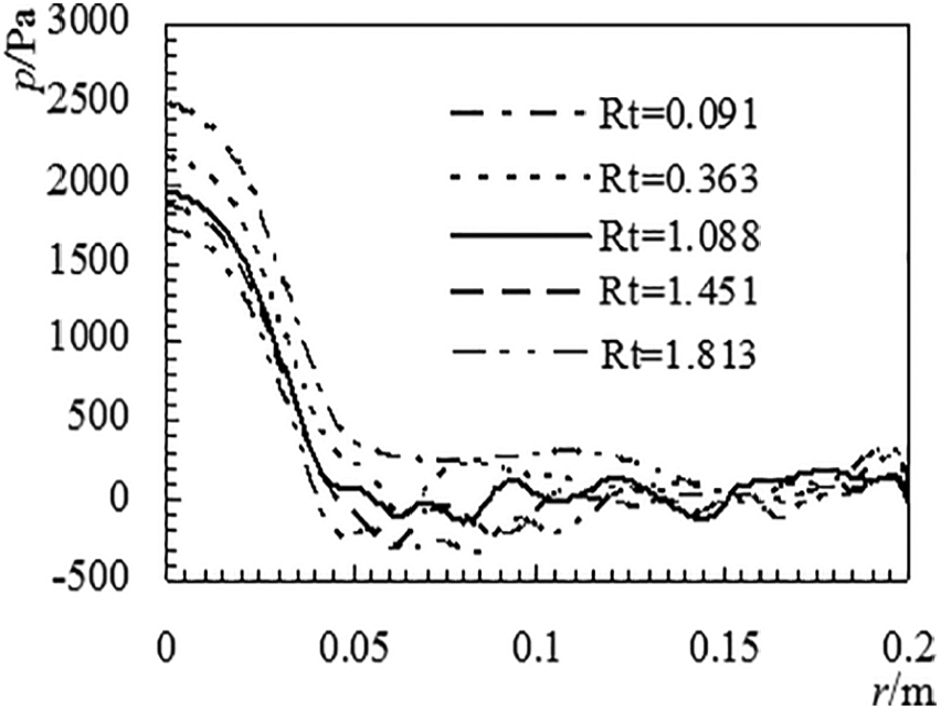
Radial distributions of relative pressure near the downstream disk wall for different Rt.
The frictional moment on the disks at different rotation number Rt
Friction moment M is the index to characterize the effect of friction temperature rise in the disk cavity. Figure 11 presents the frictional moments on both upstream and downstream disks for different Rt. The frictional moment is defined as 23

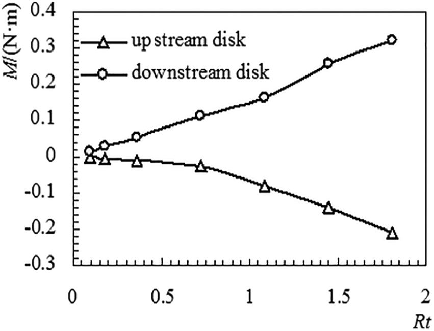
Frictional moment M variation with Rt.
Because of counter-rotating of the two disks, the frictional moments on the upstream and downstream disks are in the opposite direction. With increasing Rt by increasing the disk rotation rate Ω, the tangential velocity gradients
Conclusion
The flow structure in the counter-rotating disk cavity with axial air inflow and radial air outflow is strongly influenced by the relative strength of rotation force and inflow inertial force, which can be represented by the characteristic parameters Rt. At the Rt far smaller than 1, the fluids in the core region between the disk boundaries rotate with the upstream disk like a sandwich, and the tangential velocity of the rotating core decreases with the increase of radius. At the Rt larger than 1, the fluids on the upstream disk side are brought on rotation like the Batchelor-type flow, while the sandwich rotation disappears in the fluid on the downstream disk side.
The temperature on the upstream disk wall increases and then decreases with an increasing value of Rt, and the critical value of Rt for the change of temperature variation is assessed to be at about Rt = 0.69. The temperature and radial temperature gradient of the downstream disk wall decrease with increasing Rt.
With increasing Rt by increasing the disk rotation rate, the pressures near the downstream disk decrease.
Both the frictional moments on upstream disk and downstream disk increase with increasing Rt by increasing the disk rotation rate Ω. Due to the effect of flow structure, the frictional moment on the upstream disk is smaller than that on downstream disk.
Footnotes
Handling Editor: James Baldwin
Declaration of conflicting interests
The author(s) declared no potential conflicts of interest with respect to the research, authorship, and/or publication of this article.
Funding
The author(s) disclosed receipt of the following financial support for the research, authorship, and/or publication of this article: This work was supported by the National Natural Science Foundation of China (Grant No. 51306201), the Science Research Foundation of Civil Aviation Flight University of China (J2019-033), and the Sichuan Province Science and Technology Program (2019YJ0722).