
Abstract
The robust design optimization of an airfoil needs to continuously realize the probability-based aerodynamic simulation for various combinations of geometry and wind climate parameters. The simulation time is lengthy when a full aerodynamic model is embedded for the numerical iteration. To this end, a second-order polynomial-based response surface model is first presented to relate the airfoil performance indicator with geometry and random aerodynamic variables. This allows to quickly evaluate the response moments and optimization constraints. Then, the robust design optimization is formulated to simultaneously maximize the mean aerodynamic performance and minimize the variance of design results due to the variation of geometry and aerodynamic parameters. The robust design optimization based on the NACA63418 and the DU93-W-210 airfoils with random Mach and Reynolds numbers is presented to demonstrate potential applications of this proposed model. Results have shown that the mean-value aerodynamic indicator is generally improved, whereas the variance is minimized to archive the robust design objective. The proposed approach is simple and accurate, suggesting an attractive tool for robust design optimization of airfoils with random aerodynamic variables.
Keywords
Introduction
As a key facility to convert wind energy into electricity, the design and analysis of wind turbines have received considerable attention in recent years. 1 Along with probabilistic methods to quantify fatigue and reliability problems of wind turbine structures,2–4 the consideration of randomly aerodynamic parameters becomes crucial for the design optimization of wind turbine airfoils.
In reality, numerical optimization of an airfoil is typically divided into several sub-problems, that is, geometry modelling, aerodynamic simulation and robust design optimization. In this regard, the geometry modelling of the airfoil can be realized using a group of basis functions to translate the discrete geometry data into a continuous and smooth profile. The coefficients attached to the basis functions can be treated as design variables for design optimizations of the airfoil.5,6 Methods for the geometry modelling mainly include the Hicks–Henne (HH) method, the class function/shape function transformation (CST) method and the method based on the conformal transform theory (CTT).7,8 Even though the CTT method is flexible to represent several airfoils, the resultant trailing edge tends to be a straight line. 9 In this regard, the CST and the HH methods will be used in this article for geometry modelling of airfoils.
The aerodynamic performance of an airfoil is directly related to the power-conversion efficiency of blades. In this regard, design optimization of an airfoil is usually formulated based on aerodynamic indicators, for example, the lift coefficient
The aerodynamic simulation of airfoils can be realized based on the compressible or incompressible Reynolds-averaged Navier–Stokes equation and various turbulence models. However, the resultant computational cost will be rather critical, if a large number of aerodynamic simulations are embedded in the design optimization. In this regard, the design optimization of airfoils is alternatively implemented with the XFOIL package. 10 The design-optimization routine presented in this article, however, is potentially applicable to other aerodynamic simulation packages, once a computational procedure for the airfoil aerodynamic characteristic prediction is numerically available.
To further alleviate the computational cost, the design optimization is usually realized based on a surrogate model that links design variables (i.e. geometry parameters) of an airfoil with the aerodynamic performance indicator. Even though the aerodynamic simulation can be directly carried out by means of the computational fluid dynamics (CFD)/XFOIL model, one has to run the full-scale simulation model several times. A surrogate model based either on the Kriging or the artificial neutral network was alternatively used in the literature.11–15 The article proposes to utilize the second-order response surface model (RSM) to mimic the aerodynamic performance, and its applicability is validated using the aerodynamic optimization of the NACA63418 and the DU93-W-210 airfoils.
Rather than assuming that the aerodynamic parameters are deterministic, measurements for
The objective of this article is to present an effective approach for the robust design optimization of wind-turbine airfoils with uncertain Mach and Reynolds numbers. To implement, the geometry modelling of an airfoil is realized based on the improved Hicks-Henne (IHH) method, whereas a second-order RSM is used to mimic the implicit relation between design variables and aerodynamic indicators. A robust optimization model that maximizes the lift-to-drag ratio and minimizes the uncertain variation of the aerodynamic characteristic
The rest of the manuscript is organized as follows. Section ‘Geometry modelling of airfoils’ presents a brief summary on the geometry modelling of airfoils. The utility of the second-order RSM to mimic the true aerodynamic characteristic of an airfoil is presented in section ‘A predictive model for the aerodynamic indicator of an airfoil’. With the proposed robust design approach in section ‘Robust design optimization of airfoils’, potential applications of this approach are demonstrated by the design optimization of the NACA63418 and the DU93-W-210 airfoils. Conclusions are summarized in section ‘Conclusion’.
Geometry modelling of airfoils
The geometry modelling is a crucial step towards the design optimization of wind turbine airfoils. In this regard, the original discrete airfoil data can be represented by continuous and smooth curves to facilitate subsequently aerodynamic simulations. Basically, the CST method is commonly used for the airfoil modelling due to its strong approximation ability, whereas the IHH method is suitable for a refinement design of airfoils.
28
Specially, an S-shaped trailing edge is desired to improve aerodynamic performance of an airfoil. Note that numerical accuracy of a geometry modelling method is highly related to the investigated airfoil series, and the approximation based on a large number of basis functions are always necessary. To this end, with a brief summary on the geometry modelling technique, the performance of the CST and the IHH methods are examined by a global measure error
The CST method
The origin of the CST method can be traced back to the work by Kulfan. 29 It represents the geometry of an airfoil by means of the class and the shape functions. In this regard, the discrete airfoil data on upper and lower surfaces can be generally represented as

where the subscript
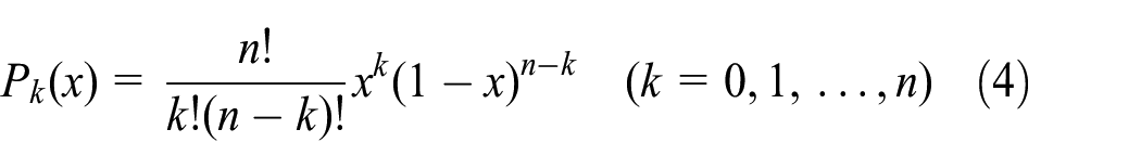
The class function

where
As discussed in the literature,
29
the parameter

Herein, parameters
Substituting for true coordinates of an airfoil, results for unknown parameters
The IHH method
Rather than directly utilizing all polynomials to represent the airfoil data, the IHH method realizes the airfoil approximation using a perturbation function around the true airfoil data. In this regard, the represented coordinates of an airfoil are expressed as

where

Herein,
In addition, the perturbation polynomial and its first-order derivative are zero-valued at

In the final polynomial term, the coefficient
Several realizations of the trailing edge based on the HH and the IHH basis functions are pictured in Figure 1. It is observed that an introduction of the last component function in equation (7) is effective to model the variation of the trailing edge to some extents. The validation for the geometry model is further presented as follows by considering the NACA63418 and the DU93-W-210 airfoils.
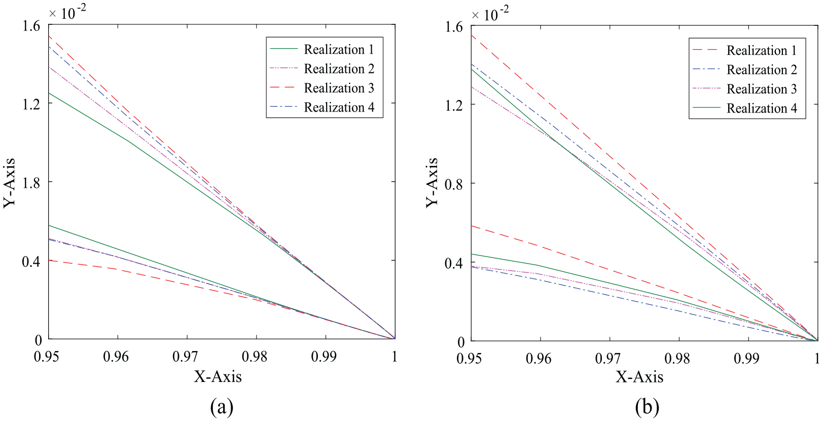
An illustration of the trailing edge based on the HH and the IHH perturbation functions: (a) the HH method and (b) the IHH method.
Numerical verification
The design optimization expects a small truncation order

which is expressed as an integral of the absolute error over an entire range of the position parameter
Numerical results for the NACA63418 and the DU93-W-210 airfoils are separatively developed based on the CST and the IHH methods in conjunction with several realizations of the truncation order parameter
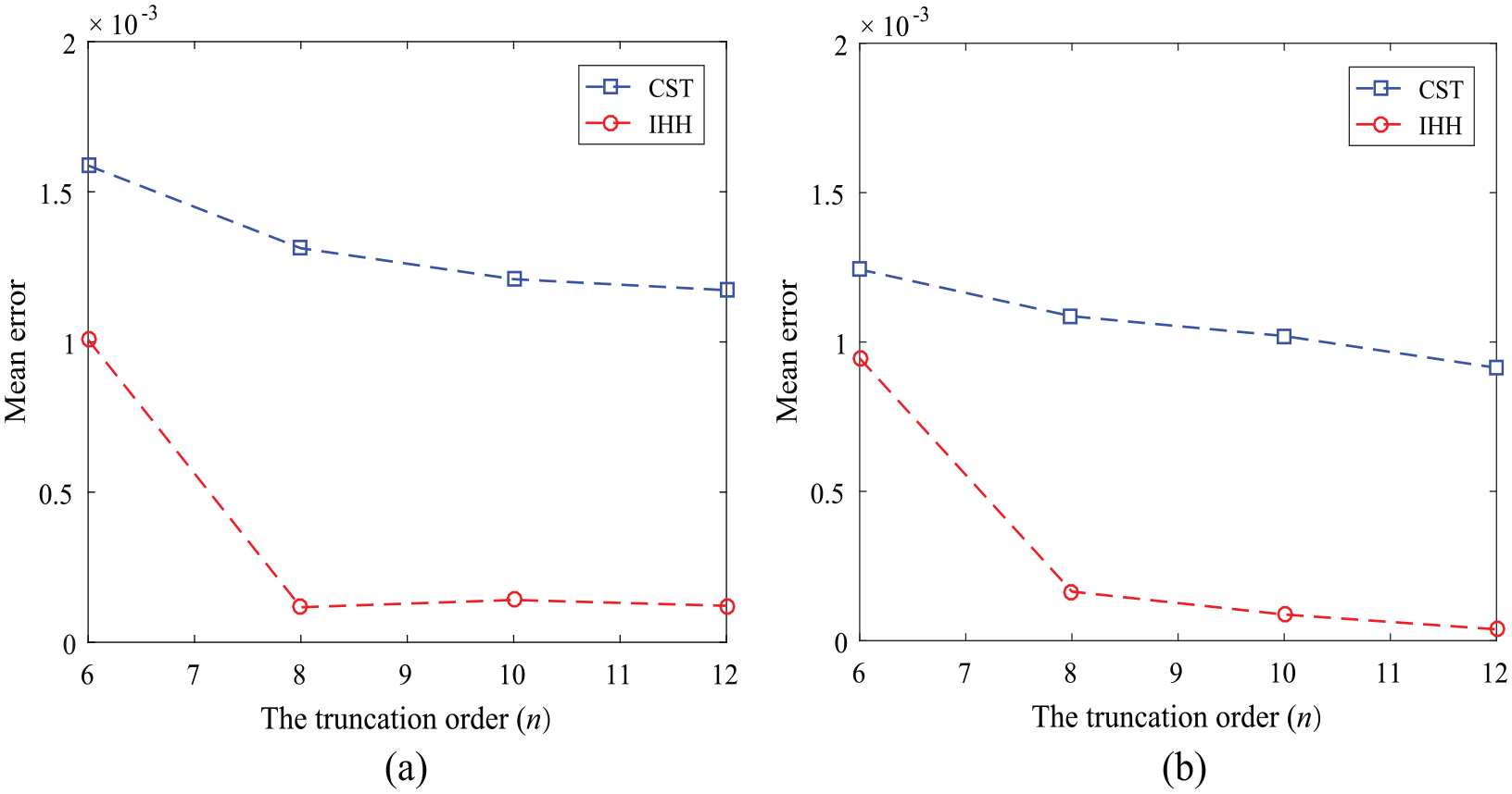
Global error for geometry modelling result of the NACA63418 airfoil: (a) the upper surface and (b) the lower surface.

Global errors for geometry modelling result of the DU93-W-210 airfoil: (a) the upper surface and (b) the lower surface.
A predictive model for the aerodynamic indicator of an airfoil
The design optimization of an airfoil requires a model to link the design parameters with the aerodynamic characteristic predicted by simulation tools.
30
In this section, a second-order RSM with cross-terms is used to approximate the true but computationally demanding aerodynamical model due to its simplicity in numerical realizations.
31
Its performance is examined against the linear and ordinary second-order polynomial model by representing the aerodynamic coefficients
The RSM
The RSM has been widely applied to represent complex input–output relations in many engineering fields. The number of training samples for a reliable estimation results needs to be positively proportional to the highest polynomial order of the surrogate model. 32 This motivates to use low-order polynomial models based on the efficiency concern in subsequent design optimizations. In this regard, the quadratic RSM including mixed terms is presented as follows
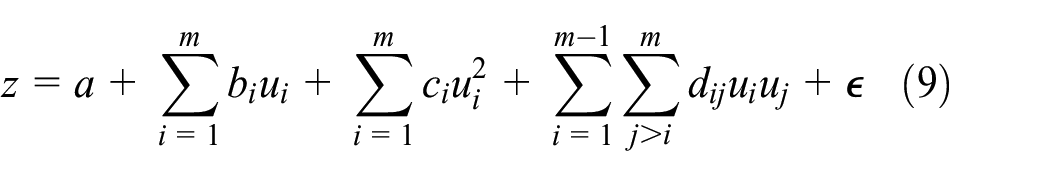
Herein, the variable
Or in a matrix form, the second-order RSM is expressed as

Following the general procedure of the design of experiment,
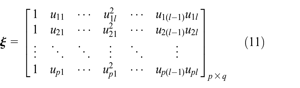
where, the parameter
Unknown coefficients in equation (10) can be calculated with the training data

as well as the covariance matrix

Here, the symbol
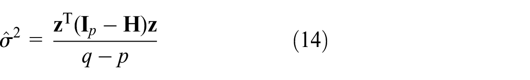
where
Once the training matrix

which is used to mimic the originally true but computationally intensive aerodynamic model response
Numerical verification
To verify the effectiveness of the quadratic RSM for the airfoil’s aerodynamic simulation, results for the NACA63418 and the DU93-W-210 airfoils are presented in this section. To implement, the IHH method with the truncation parameter

where, the mean value of the prediction result is defined as
Results for the RMSE of the
Results for the RMSE of the proposed surrogate model.

RMSE: root-of-mean-square error.
Numerical validation of the surrogate model for

Numerical validation of the RSM for the lift coefficient

Numeric validation of the RSM for the drag coefficient
Numerical results for

Results for the lift and drag coefficients of the DU93-W-210 airfoil predicted by the linear, the quadratic models with and without cross-terms: (a) results for the lift coefficient
Robust design optimization of airfoils
The aerodynamic performance, for example, the lift-to-drag ratio
The optimization model
Due to the input uncertainty, an aerodynamic performance indicator, for example, the lift or the drag coefficient and the lift-to-drag ratio

where, the function
Due to the variation of aerodynamic variables, the performance function
where
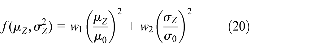
Specially, the robust design function
The following are three important robust function types in reality: 33
Nominal-the-best type

Herein,
Smaller-the-best type
Largest-the-best type

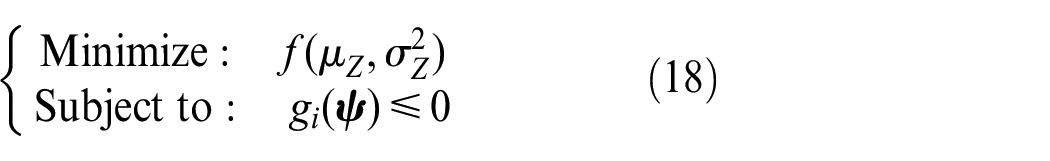
The main goal of this article is to maximize the lift-to-drag ratio, yet to minimize the variance of the uncertain aerodynamic response quantity. Therefore, a mathematical model for the probability-based robust design optimization of an airfoil is generally formulated as

In this article,
Results for the NACA63418 airfoil
The robust design optimization of the NACA63418 airfoil is first implemented based on the proposed mathematical model in equation (22). Note that the genetic algorithm (GA) coded in Matlab © is used to locate optimum results. 35
With results summarized in Table 2 and Figure 7, it is observed that results for the geometry characteristic
Results for geometry characteristics of the optimized NACA63418 airfoil.


The robust design optimization result for the NACA63418 airfoil.

Results for the empirical distribution of the maximal lift-to-drag ratio
Results for the empirical probability density function for the maximal lift-to-drag ratio
Figure 9 further summarizes results for the lift-to-drag ratio

Results of the lift-to-drag ratio
Results for the DU93-W-210 airfoil
Numerical application of the proposed approach for the robust design of airfoils is to further extended to the DU93-W-210 airfoil, where the constraint values for
Result for the robust design optimization of the DU93-W-210 airfoil.
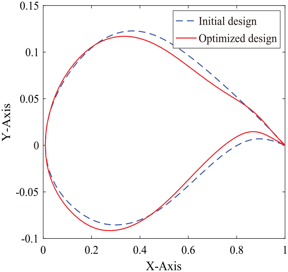
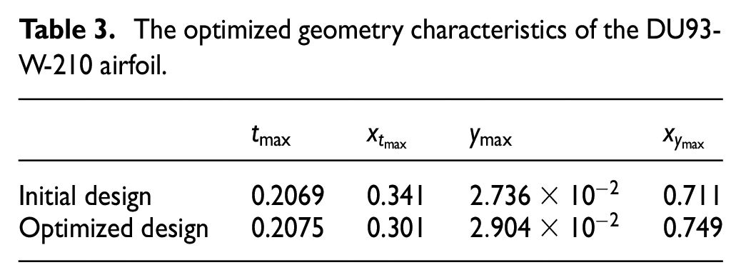
Figure 10 summarizes the initial and the optimization results for the DU93-W-210 airfoil, whereas the geometry characteristics are presented in Table 3. Besides, the empirical distribution of the maximallift-to-drag ratio simulated based on the initial and designed airfoils are pictured in Figure 11. It is observed that the mean-value of the lift-to-drag ratio has been improved by 6.93%, whereas the variance is approximately reduced by
The optimized geometry characteristics of the DU93-W-210 airfoil.
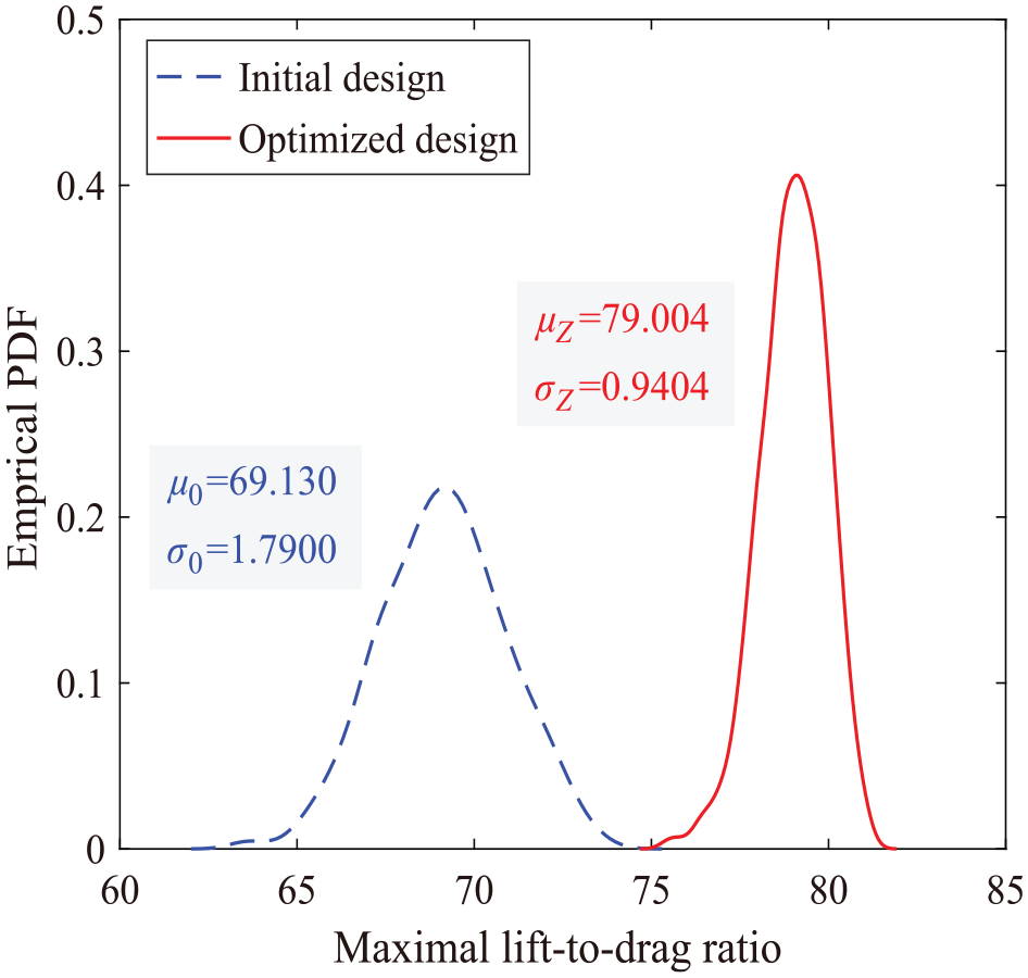
Results for the empirical distribution of the maximal lift-to-drag ratio
Figure 12 presents the relative ratio of the lift and the drag coefficients for the optimized and the initial results. Herein, the subscript
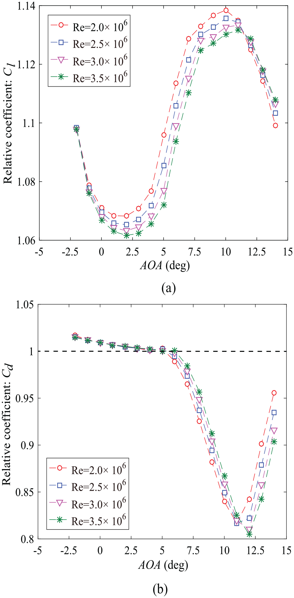
Results for relative coefficients
Figure 13 depicts results for the pitching moment coefficient

Results of the pitching moment coefficient
Conclusion
The article presents an effective approach for the robust design optimization of wind turbine airfoils with random Reynolds and Mach numbers. The geometry property of the airfoil is modelled by the IHH method. And, a second-order polynomial model with cross-terms is used to predict aerodynamic characteristics of the airfoil. With a design optimization model by simultaneously maximizing the mean-value and minimizing the variance of an aerodynamic indicator, the robust design optimization of wind turbine airfoils is demonstrated by considering the NACA63418 and the DU93-W-210 airfoils.
Numerical results have shown that the implicit input–output aerodynamic relation of the airfoil can be accurately represented using the quadratic polynomial model with cross-terms. With the optimized airfoil, the mean-value of the lift-to-drag ratio can be improved by
Footnotes
Handling Editor: James Baldwin
Declaration of Conflicting Interests
The author(s) declared no potential conflicts of interest with respect to the research, authorship and/or publication of this article.
Funding
The author(s) disclosed receipt of the following financial support for the research, authorship, and/or publication of this article: The authors would like to appreciate the Chinese National Natural Science Foundation (grant nos. 51775095 and 51405069), the Postdoctoral Science Foundation of China (grant no. 2017M610182) and the Fundamental Research Funds for Central Universities (grant no. N170308028) for financially supporting the research.