
Abstract
Transverse rumble strips are common practice to alert drivers by engaging their auditory and tactile senses in addition to visual senses by traffic signals. However, continuous exposure to noise and vibration by transverse rumble strips often results in diminished effectiveness and erratic behaviors, leading to additional safety challenges. In response, demand-responsive transverse rumble strips were developed as traffic safety countermeasures that reduce unnecessary noise and vibration associated with transverse rumble strips by incorporating active control of the rumble strips. Rather than staying static, demand-responsive transverse rumble strips are activated based on the presence of pedestrians, at predesignated times, or in response to abrupt changes in traffic flow. To evaluate the effectiveness of demand-responsive transverse rumble strips, the research team assessed noise and vibration data, both inside the vehicles and on the roadside, for various types of vehicles traveling at different speeds. The test data indicate that demand-responsive transverse rumble strips produced noticeable in-vehicle noise and vibration that could alert drivers to downstream events. Furthermore, demand-responsive transverse rumble strips generated sufficient noise to alert roadside pedestrians to vehicle presence but at low enough level to be considered as acceptable for a residential neighborhood use. Accordingly, demand-responsive transverse rumble strips could address the challenges that static transverse rumble strips face, by providing a design with relatively limited noise while enhancing safety.
Keywords
Introduction
Crashes at intersections have been one of the most significant challenges in traffic management. According to the Fatality Analysis Reporting System (FARS), 1 pedestrian–vehicle crashes were responsible for 17,551 pedestrian fatalities nationwide during the 2015–2017 period, which is approximately 16% of total traffic fatalities. The number of these crashes has increased in the United States over the past several years due to various factors (e.g. distraction, fatigue, dizziness, and low visibility). 2 Of these factors, distracted driving has become a significant concern over the years, accounting for a large portion of total traffic fatalities, estimated at 9% in 2017. 3 Among the fatalities due to distracted driving, 14% involved cell phone usage. 4
While visual signals are some of the most common approaches to alert drivers to the need to slow down, pay attention, or stop, their effectiveness is limited by factors such as distractions, fatigue, and/or low visibility. In response to these challenges, several traffic safety countermeasures that focus on enhancing the safety of pedestrians have been developed. 5 For example, the use of transverse rumble strips (TRS) has increased at intersections with high crash potential. TRS are warning devices that can alert drivers who miss visual signs by generating in-vehicle noise and vibration that are higher than ambient conditions.
Despite the effectiveness of TRS to alert drivers by giving extra noise and vibration, their effectiveness tends to diminish over time6,7 as drivers become familiar with their locations, and the effect of a sudden alert is reduced. 8 In addition, continued exposure to TRS may cause erratic maneuvers by some drivers who are trying to avoid them, 7 which may lead to additional crashes. 9 Moreover, the roadside noise produced by TRS is a concerning issue for adjacent residents, as TRS create noise each time a vehicle passes over them, and studies have shown that prolonged exposure to traffic noise can lead to negative health effects.10–12
To mitigate the identified challenges associated with TRS, this article discusses the alternative solution of demand-responsive transverse rumble strips (DRTRS), which use active control of the rumble strips. The proposed system will automatically lower the pavement under the strips to activate a rumble effect to alert drivers to roadway conditions. The system will be level with the road when not in use, thereby reducing the problems associated with TRS, as described above.
This research aims to develop and validate DRTRS in terms of their ability to mitigate the practical challenges associated with TRS. More specifically, this article evaluates the noise and vibration of both in-vehicle and roadside conditions caused by an active DRTRS. The article also includes system development, system installation on an actual roadway, data collection, data analysis, and conclusion/discussion.
Background
Noise and vibration for inattentive drivers
As of now, most traffic safety countermeasures at intersections are related to signs and signals that require engaging drivers’ visual attention. As one of the common ones, pedestrian hybrid beacons were found to contribute to safety by reducing vehicle–pedestrian crashes by 69%; 13 however, the drivers were required to be aware and attentive while driving, and its effectiveness diminished with inattentive drivers. To the problem of inattentive drivers, stimulation of their auditory and tactile senses is considered as an effective way to regain the attention of distracted drivers when their visual sense is distracted. TRS allow the mechanisms that typically engage the acoustic and haptic senses to regain drivers’ attention in response to a downstream event, prompting them to take preventive action.6,7,14 A study 6 shows that a change of 2.5–4.25 ms−2 in in-vehicle vibrations could sufficiently stimulate the haptic sense of drivers.
Literature has shown various findings related to detectable noise. One study indicated that an increase in the sound level, from the ambient noise level, by 4 dB is detectable, 15 while another study indicated that 7 dB is detectable. 16 Other studies have demonstrated that TRS can generate an extra 10–17 dB of in-vehicle noise14,17 and up to 2.55 ms−2 of vibration, 18 compared with those produced only by ambient roadway conditions. This extra noise and vibration has been found sufficient to alert drivers. Additional studies18,19 have presented similar findings, confirming the effectiveness of TRS in creating additional noise and vibration, resulting in crashes being reduced by up to 60%.9,20 Despite this positive impact, continued exposure to TRS reduces effectiveness. One study concluded that the effectiveness of haptic signals depended on the suddenness of vertical deflection. 8 With increased familiarity and awareness of TRS location, the suddenness and thus effectiveness are reduced. In addition, exposure to TRS has been found to cause erratic maneuvers (e.g. swerving) for some drivers wishing to avoid unwanted noise and vibration, 7 which can contribute to crashes. 9 DRTRS developed in this research particularly address this problem, and the detailed design, experiment, and validation are subsequently discussed.
Roadside noises by TRS
Although proper in-vehicle noise is important for alerting drivers, roadside noise generated by TRS is a concerning issue for adjacent neighborhoods.21,22 Continual exposure to noise above audible limit is responsible for mental disturbances and other hearing complications.10,11 In response, previous research conducted various studies to identify optimum dimensions of TRS that could reduce roadside noises.14,19,23 Nonetheless, roadside TRS noises were found to be a significant challenge as they were distinguishable even at half mile away. 16 To that concern, DRTRS are an alternative design that eliminates the potentiality of errant driving to avoid the bumps from the strips and reduces roadside noises by remaining inactive while there is no downstream event.
Design and dimension of TRS
While the earlier research has included various studies that identify the optimal dimensions of TRS to increase in-vehicle noise while reducing roadside noise,14,19,23 there are no universally accepted designs for TRS. For example, in Alabama, Florida, Georgia, Kentucky, Mississippi, and South Dakota, raised strips are used, whereas in Arkansas, Colorado, Idaho, Iowa, Kansas, Michigan, and West Virginia, grooved rectangular rumbles cut into pavements are used. In other states, including Illinois, Nebraska, North Dakota, Ohio, Oklahoma, and Wisconsin, both raised and grooved TRS are used.14,17,24 Furthermore, the strips in use have varying dimensions. For example, the number of strips in a set vary from 5 to 25, 25 and strip width changes between 3 ft and the full length of a lane. 25 In addition, the lengths of individual strips range from 2 to 18 in, with some states using those of 4 in.26–28 The range of height or depth also varies between 0.188 and 1.5 in.24,25
An et al. 14 and Haron et al. 17 evaluated the in-vehicle noise with different shapes and dimensions (including 2″ width, 0.4″ depth, 8″ center-to-center distance; 0.35″ width, 0.25″ depth, 1.85″ center-to-center distance; 12″ width, 0.25″ depth, 18″ center-to-center distance) for rectangular shaped and semicircular shaped TRS (4″ width radius, 0.4″ depth, 12″ center-to-center distance). The authors concluded that all variants of TRS regardless of their shape and dimension were effective to generate sufficient in-vehicle noise that could alert drivers, which was supported by other similar studies as well.6,16,18,19,24 As depth is the major contributing factor to in-vehicle vibration,29,30 much research has focused on identifying the optimum depth, leading to a standard of 0.5 in in most states.19,25 However, states including Alabama, Arkansas, Mississippi, and Oklahoma practiced higher depth of 0.625, 1.5, 1, and 0.875 in, respectively, although their effects on in-vehicle vibration were unknown. 24 Nonetheless, any depth greater than 0.6 in was not effective in operations. 8
The current study developed a prototype of DRTRS with appropriate dimensions to cause both sufficient in-vehicle noise and vibration to regain the attention of the drivers and be mostly congruent with jurisdictional practice as well. The design and dimensions of DRTRS are discussed in detail in the “DRTRS design methodology” section.
DRTRS design methodology
The design goal for DRTRS was to maintain the desirable vibration and sound properties of traditional TRS while improving long-term effectiveness by removing driver familiarity. The developed system should only provide the rumble effect when required. In addition, the DRTRS were to be practical—easy to install and maintain—which leads to a design where rumble strips could be actively lowered into roadway to avoid damage from street sweeping or snow plows.
Conceptual description
DRTRS were designed to operate on-demand, based on active downstream events that necessitate alerting drivers. Figure 1 shows the overall conceptual operation of the system with several different activation (lowering the strips) and deactivation (taking the strips back to road level) schemes. The activation and deactivation schemes are as follows:
Push Button Event: Pedestrians can engage the system with a crosswalk push button.
Pedestrian Detection Event: A thermal imaging camera is installed to automatically detect pedestrians at the crosswalk in case the push button is not used.
Timed Activation Event: The system can be activated at specific times of the day, such as for school zones.
Remote Control Event: A remote signal can be sent to activate the system in response to emergencies.
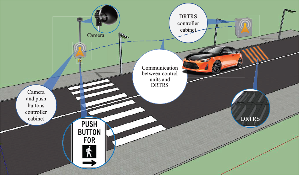
Conceptual operation of DRTRS.
Figure 2(a) and (b) shows the implementation of DRTRS prototype and pedestrian crosswalk, respectively, on an actual roadway. The distance between DRTRS and crosswalk is 200 ft, calculated by considering perception reaction and braking distance. Figure 3 shows the main components used for implementing the prototype.
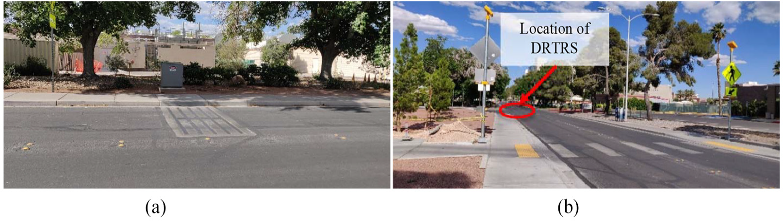
Implementation of DRTRS: (a) DRTRS and (b) crosswalk.

Schematic design and detailed specifications of DRTRS: (a) exploded view of a rumble unit and (b) detailed view showing the components of rumble strip units with the left unit inactive (at roadway level) and the right unit active (lowered).
Mechanical design and prototyping
DRTRS are designed to be enclosed in a steel box that is embedded in a roadway (Figure 3). The five hydraulically actuated rumble units are equally spaced within a box that is placed transverse to the flow of traffic. The 4-in-wide rumble strips are spaced at 12 in center-to-center distance. Each rumble unit is topped by a C-channel beam, which can be lowered and raised to create a rumble effect. The depth of the rumble is half of an inch. The rumble units are separated by metal troughs filled with concrete to provide stiffness and stability.Each unit can be quickly disassembled in case of a mechanical failure or required maintenance. The system is designed to maintain functionality under various environmental conditions, including rain, snow, and dirt, as well as temperature variations. Since the rumbles are lowered into the roadway, there is reduced risk of damage from street cleaning or snow plowing.
Figure 3(a) shows the exploded view of a single rumble unit. The main design details of DRTRS are shown in Figure 3(b), which presents the key components of a rumble unit: a hydraulic actuator, C-channel beam, support column, and base plate. Rumble strips and metal troughs are bolted to the steel box, which is fixed to the road using studs and epoxy. Hydraulic lines connect the actuator to a hydraulic pump and a controller unit placed in a cabinet on the side of the road, as shown in Figure 4.

DRTRS control cabinet.
To move the rumble units to the default position (level with the roadway), the hydraulic pump is turned on, allowing the hydraulic actuators and springs to push the C-channel beams up. To lower the rumble units, hydraulic actuator valves are opened, allowing gravity to lower the strips, which creates the rumble effect. Figure 5 shows the inactive and active states of DRTRS that were installed on a roadway.

Inactive (left) and active (right) states of DRTRS.
Experimental setup
Experimental evaluation was designed to measure the in-vehicle noise and vibration to determine whether DRTRS could alert drivers to potential downstream events. In addition, the experiment incorporated the measurement of roadside noise and vibration created by the active DRTRS and their effects on the surrounding neighborhood.
Test plan
A DRTRS prototype was installed on a road within the campus of the University of Nevada, Las Vegas (UNLV), as shown in Figure 5. In order to evaluate the effectiveness of the system, it was tested using three test vehicles: a diesel truck (Ford F250), SUV (2017 Nissan Rogue S), and sedan (2012 Honda Civic). The drivers of these vehicles were asked to drive over DRTRS at three different speeds (15, 25, 40 mph). Each condition (e.g. active DRTRS, in-vehicle data for SUV at 25 mph) was repeated three times, resulting in a total of 54 trials. Active DRTRS data were compared with reference data from the ambient roadway.
Data acquisition
During the tests, the following high-resolution data were collected: (1) in-vehicle noise (dBA), (2) in-vehicle vibration (ms−2), (3) roadside noise (dBA), and (4) roadside vibration (ms−2). This research used a data acquisition unit (NI cDAQ-9178), a sound level meter (SLM) (QUEST 2700), and a triaxial piezoelectric accelerometer (Endevco® Isotron® accelerometer, 45 A).
Figure 6 shows a diagram presenting the data acquisition and flow during the experiment. Data were collected at 10 kHz using LabVIEW through the NI-DAQmx API and saved in a timestamped.csv file for post-analysis.

Block diagram of data acquisition with SLM and accelerometer.
Noise and vibration measurement setup
Figure 7(a) and (b) shows the setup of the instruments during the roadside experiments. The SLM was aimed toward DRTRS to attenuate unwanted noise, mounted at a height of 4 ft, and located 13 ft away from the center of DRTRS. The accelerometer was placed on the sidewalk and was covered by a 5-lb soft mesh lead shot weight to absorb high-frequency vibrations. The x, y, and z axes of the accelerometer were aligned with respect to the lateral, longitudinal, and vertical directions of the roadway, respectively.

Data acquisition setup: (a) SLM setup for roadside experiment, (b) accelerometer setup for roadside experiment, (c) SLM setup for in-vehicle experiment, and (d) accelerometer setup for in-vehicle experiment.
Figure 7(c) and (d) shows the setup of the instruments during the in-vehicle experiments. The SLM was placed on a tripod at the ear level of the driver (Figure 7(c)) to approximate the actual driver’s perception. The accelerometer was mounted on the steering column to minimize the effects of the vehicle’s suspension on the measured vibration. 14 The accelerometer was placed between two 5-lb soft mesh lead shot weights to absorb high-frequency vibrations and to ensure its stability during the experiment.
Data processing
Given DRTRS spacing of 12 in, the DRTRS-induced vibrations at the highest test speed (40 mph) were expected to be 58.67 Hz. Frequency analysis showed almost all vibration was below 60 Hz. Therefore, all data were filtered using a first-order LP Butterworth filter with 60 Hz cutoff frequency. It was deemed that the sound signals had limited higher order noise and were not filtered.
Figure 8 shows examples of in-vehicle and roadside noise, and filtered vibration data collected from an SUV at a 25-mph speed while passing over active DRTRS. Figure 8(a) and (b) shows that the front wheels hit the rumbles at 2.72 s and the back wheels at 3.02 s for the in-vehicle experiment. Similarly, in Figure 8(c) and (d), these events occurred at 2.45 and 2.73 s for the roadside case. Note the sharp peaking in noise and vibration while over the DRTRS.

In-vehicle and roadside noise and vibration data for a case of SUV running at 25 mph over active DRTRS: (a) in-vehicle noise, (b) in-vehicle vibration, (c) roadside noise, and (d) roadside vibration.
Results
In-vehicle noise and vibration
Peak noise and magnitude of vibration are used to assess the DRTRS performance. 16 Table 1 provides the data for in-vehicle noise measured at ambient roadway conditions. Ambient noise is consistent for each vehicle but increases due to engine noise at higher speeds. Figure 9(a) shows the in-vehicle noise when passing over DRTRS, and Figure 9(b) shows the increase in in-vehicle noise, which is computed by subtracting the ambient data (Table 1) from the in-vehicle noise data.
In-vehicle ambient noise in decibels.

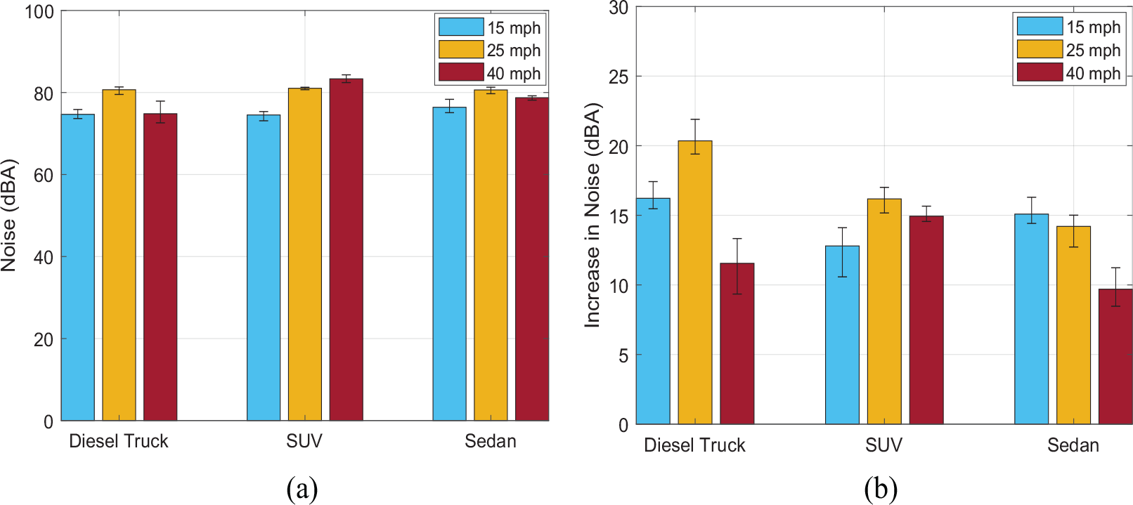
In-vehicle noise and increase in in-vehicle noise due to active DRTRS: (a) in-vehicle noise for different vehicles and (b) increase in in-vehicle noise for different vehicles.
Based on the literature review, 7 dBA is the detectable threshold of noise for most individuals. 16 Figure 9(b) shows that in all test scenarios, the increase in noise when a vehicle passed over the active DRTRS was greater than 7 dBA. While the increase in in-vehicle noise varied with vehicle speed and type, such variations seemed reasonable because each test scenario had a unique dynamic interaction between the test vehicle and DRTRS due to differences in engines, suspension mechanisms, sizes of car components, and test parameters. Sound generally increased as speed increased, but the noise differential was the lowest at the highest speed. This decreased sound at higher speed is likely due to reduced deflection time (e.g. tires skipping DRTRS rumbles), as well as louder engine noise at higher speed.
Figure 10 shows the increase in in-vehicle vibration for the test cases, due to active DRTRS. Similar to in-vehicle noise, the results varied with speed and vehicle type, but were consistently above the upper ceiling of detectable vibration of 4.25 ms−2. The only exception was in-vehicle at 40 mph in the case of the diesel truck, which might be explained by the larger tire size and nature of the vehicle’s suspension absorbing more vibrations.

Increase in in-vehicle vibrations.
Therefore, active DRTRS were effective in engaging both the auditory and tactile senses of the drivers of these passenger vehicles, with discernible noise and vibration. However, since the diesel truck experienced lower vibration and noise at higher speed, active DRTRS may not have a discernible effect on other heavy vehicles.
Roadside noise and vibration
Similar to the previous section, the ambient roadside noise is shown in Table 2. Figure 11 shows the ambient roadside noise and the associated increase in roadside noise for the test vehicles. Interestingly, the roadside noise exhibited a consistent positive correlation with speed for all tested vehicles. In addition, the increase in roadside noise was typically beyond the noise threshold of 7 dBA. 16 The increase in roadside noise for passenger cars (SUV and sedan) was significant enough to be distinguished by pedestrians at any given speed.
Roadside ambient noise in decibels.


Roadside noise exerted and increase in noise by active DRTRS: (a) roadside noises for different vehicles and (b) increase in roadside noises for different vehicles.
Furthermore, the roadside vibration exerted by the active DRTRS was only 0.5–0.8 ms−2 for any given condition, which was too minimal to perceive, and therefore excluded from further analysis.
Noise created by vehicles due to the active DRTRS was sufficient to alert roadside pedestrians while having little additional noise in the adjacent neighborhood.
Discussion
Active DRTRS have been shown to be effective in engaging the auditory senses of drivers by generating in-vehicle noise above the minimum threshold of discernible noise for passengers in vehicles, including an SUV and a sedan. However, at higher speeds, DRTRS did not create distinguishable in-vehicle noise for a diesel truck. Nonetheless, active DRTRS were effective in engaging the haptic senses of all drivers, which are associated with sufficient in-vehicle vibration, irrespective of vehicle type or running speed.
DRTRS generate noise that are higher than roadside ambient noise, sufficient for roadside pedestrians to hear, in the active state. Yet, the inactive state has noise pollution similar to ambient roadway conditions, meaning the use of DRTRS could have a positive impact on adjacent neighborhoods.
DRTRS provide flexibility for a wide variety of applications besides pedestrian crossings. During school hours, DRTRS should always remain active with the intention of alerting drivers passing the school zone regardless of the presence of pedestrians. On highways, DRTRS can be used as a warning tool for over-speeding and wrong-way driving with activation if drivers exceed posted speed limits or travel in the wrong direction.
An advantage of the dynamic nature of DRTRS is that drivers might not get accustomed to its placement since it only responds to a meaningful event. Consequently, the on-demand activation of DRTRS may have some added benefits compared with static TRS, including the ability to maintain the effect of alerting drivers over time, to reduce potential safety challenges from erratic avoidance maneuvers, as well as to produce a customized warning system per road requirement either in residential neighborhood or in highways. However, these potential benefits must be investigated further.
Finally, the researchers note that it may be necessary to optimize the number of rumbles, their spacing, and dimensions based on the needs of a specific jurisdiction. Differing dimensions yield different levels of noise and vibration, and the appropriate levels must be tuned for the application, for example, low noise pollution in neighborhoods or extreme noise and vibration on a highway.
Conclusion
DRTRS, a new potential traffic safety countermeasure, can provide advance warning on demand to reduce the issues of extraneous noise and vibration associated with TRS. Drivers will generally experience the natural feeling of an ambient roadway most of the time with inactive DRTRS. Upon the detection of a potential downstream event, DRTRS become active and lower their array of strips to alert drivers in a similar manner as traditional TRS. Experimental evaluation has shown that the designed DRTRS are effective at producing haptic and auditory changes necessary to regain driver attention. In addition, DRTRS can be used in school zones and residential areas, where roadside noise is objectionable, given that they will remain inactive and, therefore, produce no rumbling noises until an event requiring their activation occurs.
Footnotes
Acknowledgements
The researchers would like to express their great appreciation to the US DOT-RITA, Nevada DOT, and the Nevada Governor’s Office of Economic Development sponsors. In addition, the researchers would like to acknowledge the support provided by Adam Betemedhin, Anthony Filipak, David Zagaceta, Richard Jennings, and Steve Merrill. The publication fees for this article were supported by the UNLV University Libraries Open Article Fund.
Handling Editor: James Baldwin
Declaration of conflicting interests
The author(s) declared no potential conflicts of interest with respect to the research, authorship, and/or publication of this article.
Funding
The author(s) received no financial support for the research, authorship, and/or publication of this article.