
Abstract
In this study, a method for analyzing the fatigue strength of a bogie frame under a random load was proposed. Based on the geometric features, a welded joint coordinate system was established to compute the stress components of each node in this coordinate system. With the influence of small amplitude cycles included, based on the corrected S–N curve and a method for calculating the equivalent constant amplitude stress, the node and comprehensive degree of utilization were calculated based on the anti-fatigue design grade of welded joints to evaluate the fatigue strength of a structure under a given lifespan. The FKM and International Institute of Welding methods were used to evaluate the fatigue strength of typical welded joints of a bogie frame. The characteristics of the node degree of utilization under different analytical methods were compared, and the results showed that when the time histories of the three stress components of the nodes had significant non-proportional features, the FKM method obtained conservative results. When the time histories of the three stress components of the nodes were synchronized, the criterion value specified by the International Institute of Welding method was the main factor affecting the distribution characteristics of the node degree of utilization. The analysis based on the International Institute of Welding method can effectively balance the lightweight design and reliability of the structure.
Keywords
Introduction
The welding frame is an important bearing component of a bogie and its fatigue strength has attracted considerable attention. When a vehicle is running, the bogie frame is subjected to the car body vibration load, driving load, braking load, vibration load of the large mass suspension component, load of the suspension system components, and twist load caused by track irregularities. The stress on the bogie frame is randomly distributed.
In recent years, studies on the fatigue strengths of bogie frames with randomly distributed stresses have been conducted.1–4 For the differences between the dynamic load characteristics of a vehicle running on straight and curved lines, Dietz et al. 1 proposed a method for predicting the fatigue life of a railway bogie based on the frequency domain and time domain methods. Yang 2 established a rigid-flexible coupled dynamics analysis model of the DF4D locomotive of the China Railway, introduced the low-order mode of the bogie frame, used the quasi-static superposition method to obtain the stress-time history and stress spectrum of the area to be inspected, and evaluated the fatigue strength of the bogie frame based on the Palmgren-Miner’s rule. Introducing the elasticity of the car body and bogie frame in a dynamic model of the vehicle system, Liu and Shao 3 calculated the characteristics of the dynamic load and dynamic stress of a vehicle system with the European Rail Research Institute track irregularities. Lu et al. 4 established a high-speed train dynamics analysis model to obtain the load and time history of each part of the bogie frame. The modal superposition method was used to study the influence of structural vibrations on the fatigue strength of the bogie frame based on the Palmgren-Miner linear cumulative damage criterion and the P–S–N curves of the materials. In the studies described above, which were all based on the time history of the uniaxial equivalent stress, the stress spectrum was generated using the corresponding counting method, the cumulative damage at the investigation point was calculated using the Palmgren-Miner’s rule, and the fatigue strength of the bogie frame was evaluated based on whether the cumulative damage was greater than 1.
According to recent studies,5–10 stress characteristics have a significant impact on the fatigue strengths of welded structures under random loads. First, the variable amplitude stress cycle causes more damage to the structure than the constant amplitude cycle. Sonsino and Kueppers5–8 suggested that a structure should be evaluated with a small amount of allowable accumulated damage to ensure that the fatigue strength is in a safe range. Second, in the multi-axial stress state, the stress component in the non-proportional stress state causes the principal stress direction to change over time, and the fatigue strength of the steel weld is severely weakened. Thus, a modified strength theory should be used to evaluate the fatigue strength of the steel weld.5,9 Based on the notch stress method, Shen et al. 10 built a finite element model of a typical welded joint to explore the fatigue strengths of welded joints in multi-axial stress states using different strength criteria. In addition, the “FKM Guideline: Analytical Strength Assessment of Components” also proposed an engineering method for evaluating the structural fatigue strength in a non-proportional stress state.
For a bogie frame subjected to a random load, the stress in each area is in a significant multi-axial stress state, and the stress components are typically non-proportional. Hence, analyses based on currently available methods endanger the structural fatigue strengths. Considering the limitations of currently available engineering analysis methods and based on the results of fatigue tests of typical welded joints, the contribution of small amplitude cycles to structural fatigue damage was taken into account, and the influence of the stress characteristics under random loads was fully considered to study a method for evaluating the fatigue strength of a bogie frame, which is of great significance for ensuring its structural reliability.
In order to meet the requirements of structural fatigue strength evaluation under multi-axial stress state, this study first constructed the weld coordinate system based on the geometric characteristics of the finite element model, and obtained the node’s stress components in the weld coordinate system. Using the linear superposition method, the time history of each stress component of the node is obtained, and the stress spectrum is generated. Aiming at the defects of FKM method, the calculation method of constant amplitude cyclic equivalent stress is proposed. The structural fatigue strength is evaluated based on the modified strength theory under non-proportional stress conditions. Based on the above method, the fatigue strength of the metro bogie frame under random load is analyzed, and the analysis results obtained by different methods are compared.
Node stress component in the weld coordinate system
Fatigue strength analysis of welded joints is based on the nominal stress method. According to the International Institute of Welding (IIW), the German Mechanical Engineering Society and the European Committee for Standardization, the fatigue strength of welds is directly determined by the normal stress in the direction of the welds
Welds of bogie frames can generally be divided into two types: straight and curved. The coordinate system of both types of welds can be established by examining the vector relationship between nodes, adjacent nodes, and external reference nodes.
Coordinate system of straight welds
Figure 1 shows the straight welds. If a node is defined as node A, its neighbor node is node B, and the reference node C is in the weld plane. Then, the direction vector of

where
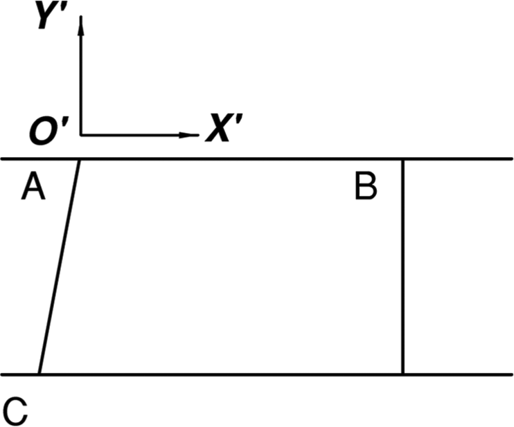
Straight welds.
The direction vector of the Y′ axis in the weld coordinate system,

where a
The direction vector of the Z′ axis of the weld coordinate system,
Coordinate system of curved welds
It is currently difficult to accurately predict the curvatures of non-circular curved welds. Since the distances between the nodes in the finite element analysis model are much smaller than the radii of the curves of the welds, it is sufficient to replace the actual shape of the welds with the arc formed by the inspection point and the two adjacent points and meet most engineering needs. The coordinate system of the curved welds is shown in Figure 2, where node D is the inspection point, nodes E and F are two adjacent nodes, and H and J are the midpoints of line segments DE and DF, respectively. When establishing the weld coordinate system, the external reference point of the welds, that is, the coordinates of the center G of the arc, should be obtained first.
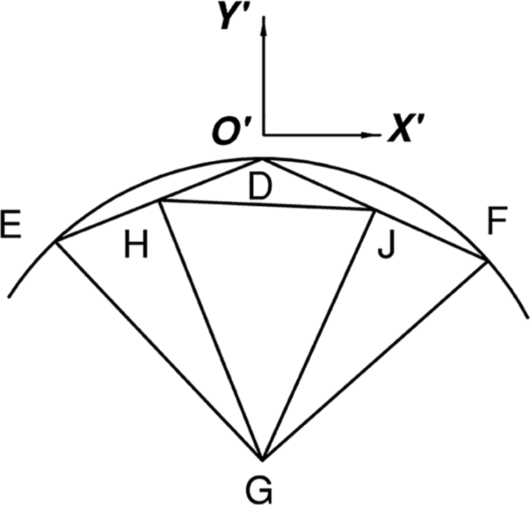
Curved welds.
The curved weld joints are shown in Figure 2, and vector

where

After the unit vector e


where r
Based on the coordinates of the center G and the inspection point D, the direction vector of the Y′ axis of the curve weld coordinate system,
Node stress components in the weld coordinate system
The stress components of the nodes in the global coordinate system include the normal stress components, that is,

where
Fatigue strength evaluation method for welded joints under random load
Time history of the stress components
When the vehicle is running on an irregular track, the bogie frame is subjected to various loads that vary with time. At time

where
The bogie frame exhibited a linear stress–strain relationship under various loads. At time
Influence of average stress
The rain-flow counting method was used to process the time history of each stress component to gain a 3D stress spectrum composed of the mean value, amplitude value, and the number of cycles of each stress component. As recommended by the FKM Guideline,

where
The fatigue strength of the weld of the bogie frame is affected by the stress cycle characteristics and the residual stress state, and a relatively high residual stress will weaken the fatigue strength of the structure. Therefore, for complex structures in a state of global residual stress, Hobbacher 9 suggested that the influence of the average stress should be ignored, and the cyclic stress spectrum should be directly determined based on the stress amplitude and the number of cycles of each 2D stress spectrum block.
Node degree of utilization component under variable amplitude load
For the longitudinal load-carrying fillet weld, Figure 3 shows the different S–N curves given by the IIW Recommendation and FKM Guideline, the parameters of which are listed in Table 1. The FKM Guideline uses an S–N curve with a fatigue limit cut-off line.
14
When the number of stress cycles

S–N curves recommended in different studies. (a) Normal stress S–N curve and (b) shear stress S–N curve.
Characteristic parameters of the S–N curve.

IIW: International Institute of Welding.
For simplicity, the FKM Guideline did not consider the influence of the fatigue limits of the welded joints when calculating the equivalent constant amplitude stress. When the equivalent constant amplitude stress
When considering the influence of a small amplitude cycle on the structural fatigue strength for structures subjected to variable amplitude loads, the method proposed by Hobbacher
9
was used to extend the S–N curve with the exponent

where
The nodes’ degree of utilization of each stress component,

where
Fatigue strength under non-proportional load
In the non-proportional stress state, the direction of the principal stress of the weld joints changes with time, which deteriorates the fatigue strength of the structure. For the purpose of engineering simplifications, the IIW Recommendation and FKM Guideline proposed methods for evaluating structural fatigue strengths suitable for non-proportional stress cycles.
Based on the fatigue test results of steel welds in the non-proportional stress state, Sonsino
8
suggested that the criterion of

If the evaluation method is unified with a node’s degree of utilization of less than 1, equation (15) must be rewritten as follows

Due to the low elongation at the break of the welds, the FKM Guideline suggests that the node’s degree of utilization

where
The FKM Guideline suggests superimposing the node’s degree of utilization in various load conditions to evaluate the fatigue strength as follows

Fatigue strength of metro bogie under random load
Bogie frame characteristics under random load
To study the fatigue strength of the welded frame of metro bogies under random loads, a multi-body dynamics model of the vehicle system was established. When the vehicle passed an S-shaped curve with a radius of 450 m and a high-level track irregularity, the time histories of the vertical load between the wheel and rail, the vertical and lateral loads of the air spring, the lateral stop and damper loads, and the twist load experienced by the bogie frame were calculated according to the method proposed by Zhu. 15
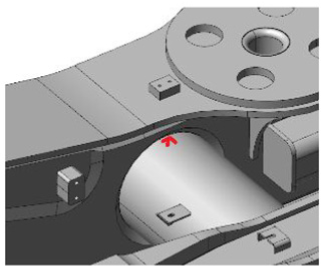
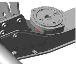
For the metro bogie frame as shown in Figure 4, it mainly bears the vertical and lateral loads of the air spring, the bump stop load, the damper load and the torsional load. Figures 5–9 show the time history of each load. As the vehicle passes the curve under the action of the unbalanced centrifugal force load, the air springs on the left and right sides of the same bogie will be loaded or unloaded, respectively, with the vertical load of the air springs taking on an opposite variation tendency. The lateral loads of the air springs on both sides have the same variation tendency, while the lateral stop load has a significant pulsation cycle characteristic. Mainly affected by the irregular tracks, the torsional load and damper load borne by the bogie frame are randomly distributed.

Metro bogie frame and its loads.

Time history of the vertical load on the central spring.

Time history of the lateral stop load.

Time history of the lateral load on the air spring.
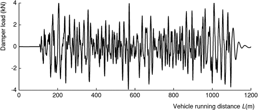
Time history of the damper load.
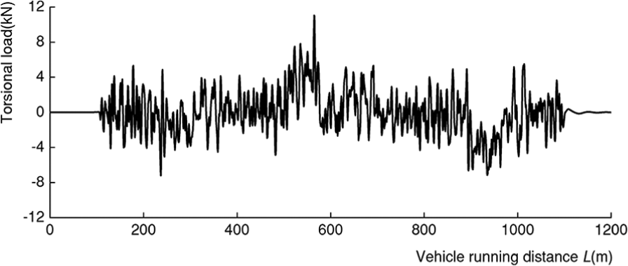
Time history of the torsional load.
Regular hexahedral elements were used for the finite element model (Figure 10). Since the analysis is based on the nominal stress method, it is not necessary to simulate the exact shape of the welded joint when building the finite element model. According to the recommendations of DVS, the stress at a certain distance, which is 1–1.5 sheet thickness from the weld toe, is used as the nominal stress of the joint. 16 A stress test was carried out on a bogie frame based on the vertical, lateral, and torsional loads specified in EN 13749 “Railway applications-Wheelsets and bogies-Method of specifying the structural requirements of bogie frames.”Table 2 shows the simulation and test results of two measurement points at the welded joint between the transom and inner web of the side frame, as well as two measurement points on the lower cover plate of the side frame. For the single-axis gauges or three axes rosettes, the stresses in the longitudinal direction of the strain gauges or the von Mises stresses are used for comparison. By comparing the results, it was found that for the above-mentioned four measurement points, the results obtained by the finite element model were larger than the test results under the corresponding working conditions, with a maximum relative error of 24.12%. The model could effectively predict the stress distribution of the structure under various loads. Based on this model, the distribution of stress on the bogie frame under a unit load for various loads was obtained and converted into the welded joint coordinate system.

Finite element model of the bogie frame.
Finite element results and that of the stress test.


Based on the above-mentioned method, the time histories of the stress components of each node were generated. Figure 11 shows the time history of each stress component of node 196178 at the welded joint between the transom and inner web of the side frame. The time histories of the three stress components of this node exhibited random distributions. The stress component

Time history of each stress component of the sample node. (a) Time history of the stress component
Fatigue strengths of welds using different methods
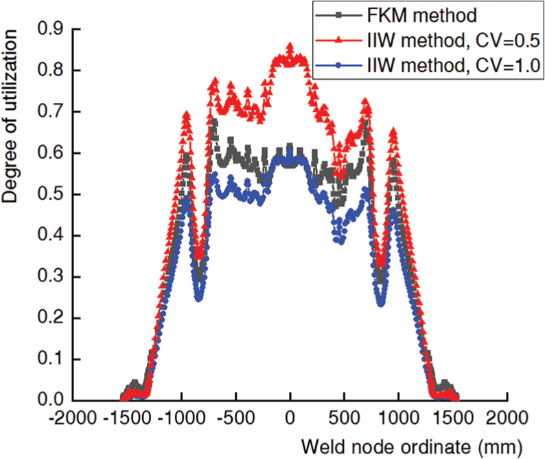
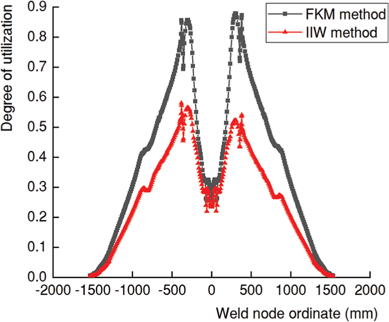
The time history of the stress components of each node were processed, and the node’s degree of utilization of the typical welds of the bogie frame were calculated based on the method proposed by the IIW Recommendation (hereinafter referred to as the “IIW method”) and the method recommended by the FKM Guideline (hereinafter referred to as the “FKM method”). Figures 12–17 show the degree of utilization of the welds between the outer web of the side frame and the upper and lower cover plates (hereinafter referred to as “weld A” and “weld B”), the welds between the inner web and the upper and lower cover plates (hereinafter referred to as “weld C” and “weld D”), and the welds between the transom and the outer and inner webs of the side frame (hereinafter referred to as “weld E” and “weld F”). These welds are marked in Figure 3.

Distribution of node’s degree of utilization of weld A.
Distribution of node’s degree of utilization of weld B.
Distribution of node’s degree of utilization of weld C.

Distribution of node’s degree of utilization of weld D.

Distribution of node’s degree of utilization of weld E.

Distribution of node’s degree of utilization of weld F.
The results showed a significant difference between the results obtained by the FKM Guideline and the IIW method. For all welded joints except welded joint B, the node degree of utilization obtained by the FKM method was greater than that gained by the IIW method. In the middle part of welded joint A, there was the largest difference between node degree of utilizations obtained using the two methods. For node 159533, the node degree of utilization obtained using the FKM method was 221.62% larger than that obtained using the IIW method. For most areas of welded joint B, the node degree of utilization obtained based on the IIW method was larger than that obtained by the FKM method. Considering node 169910 in the middle as an example, the node degree of utilization obtained based on the IIW method was 39.15% larger than that obtained by the FKM method. The FKM Guideline applied a simple but overly conservative method for evaluating the structural fatigue strength in the non-proportional stress state, which was the main cause of the above difference.
Under a single load, the time history of each stress component of the weld joints changed synchronously. According to the FKM Guideline, the node degree of utilization should be calculated based on the maximum principal stress criterion. For structures in the non-proportional stress state, the FKM Guideline suggests that the node degree of utilization under a single load should be calculated first, after which the structural fatigue strength should be evaluated through linear superposition based on the algebraic sum of the node degree of utilization under each load. If the time history of each stress component of the nodes continues to change synchronously under different loads, the time histories of the three stress components calculated according to equation (10) under the integrated action of various loads also change synchronously. At this time, the obtained node degree of utilizations will have the same value, whether it is calculated based on the stress-time history under the integrated action of various loads or based on the stress-time history under each load alone. The difference between the node degree of utilization obtained using the IIW method and that obtained using the FKM method is determined only by the criterion value, CV. For general cases, with the simultaneous action of different loads, the loads are not correlated with time. Under the combined action of various loads, the time histories of the three stress components of the nodes exhibit non-proportional variations. If the calculation is based on the superposition method determined by the FKM Guideline, the time history of the stress component under different loads should be characterized by proportional variations. The node degree of utilization obtained based on this simplified method tends to be conservative. The more significant the synchronism is between the time histories of the three stress components obtained according to equation (10), the closer the results obtained by the FKM method are to the actual fatigue damage level of the welded joints. Hence, without considering the criterion value, CV, the node degree of utilization obtained based on the FKM method will be larger than that obtained based on the IIW method.
For some nodes, the criterion value
Conclusion
Accounting for the influence of small amplitude cycles on structural fatigue damage, the S–N curve recommended by the FKM Guideline and the equivalent constant amplitude stress calculation method were corrected.
Based on node stress components in the weld coordinate system, a method for evaluating the fatigue strengths of bogie frames under random loads was determined based on the IIW and FKM methods to evaluate the fatigue strengths of typical welds. For different welded joints, there were differences in the distribution of node degree of utilizations obtained based on the different methods.
For welded joints with significant non-proportional characteristics between stress components, the node degree of utilization obtained using the FKM method was larger than that obtained using the IIW method. When the stress components of the weld joints were synchronized, the difference between the node degree of utilizations obtained using the FKM and IIW methods was mainly determined by the criterion value CV.
The FKM Guideline provides a conservative approach to structural fatigue strength analysis. The fatigue test results of typical welded joints confirm the effectiveness of the IIW method. Therefore, the IIW method is used in the fatigue strength analysis of the welded structure under the spectrum load, which can effectively balance the lightweight design and reliability of the structure.
Footnotes
Appendix 1
The equivalent constant amplitude stress of the variable amplitude cycle is calculated as follows.
The damage caused by a spectrum block is calculated as follows
where
When the exponent of the S–N curve is
According to Hobbacher’s suggestion, the S–N curve is extended with the exponent
When the stress range is
According to equations (20) and (21),
Similarly, when
In this case,
Handling Editor: Liyuan Sheng
Declaration of conflicting interests
The author(s) declared no potential conflicts of interest with respect to the research, authorship, and/or publication of this article.
Funding
The author(s) received no financial support for the research, authorship, and/or publication of this article.