
Abstract
In this study, a coil gun was designed using a trigger that can discharge a capacitor using physical contact. Controlling the discharge time of the capacitor in a multi-stage coil gun is an important factor for the final velocity of the projectile. To control the discharge time, we used the physical contact of the projectile and the trigger and controlled the point in time when discharge occurs by sensing the projectile location using a sensor. Controlling the discharge using sensors allows for more accurate timing control than physical discharge systems, but the circuit is more complex, and the high current results in a higher risk of malfunction and higher costs. In contrast, systems that use physical contact are simple, have low risk of malfunction, and have low cost. The velocity of the projectile was predicted using the electromagnetic analysis simulation program MAXWELL, and the final velocity of the projectile was compared to the results of a prototype.
Introduction
A coil gun is a device that accelerates a projectile using electromagnetic force, which is generated around a coil when an electric current flows through it for a short period of time. A multi-stage solenoid coil design is required to improve the final velocity of the projectile.1–4 The projectile moves through the passage and accelerates when current is applied to the next solenoid coil. The final velocity of the projectile is significantly affected by the discharge time of the capacitor connected to the solenoid coil according to the projectile’s position. 5
The discharge time can be controlled using a limit switch based on physical contact or a sensor. A limit switch is used to control the movement of the elevator and the factory conveyor belt. The current can be turned on and off based on a simple principle and operation. It is an electric component that is widely used in industry due to its simple manipulation, ease of installation, and operational reliability. The operating principle of a limit switch involves a physical connection of the actuator to various contacts, and if an object is in contact with the actuator, the electrical circuit is connected or disconnected. A switch was manufactured to discharge the coil gun’s capacitor using the operating principle of a limit switch.
Previous studies used optical sensor to control the discharge time of capacitors. The location of the projectile was determined using an optical sensor and used to determine when to discharge the capacitor. The discharge circuit using the optical sensor is complicated to design, and the very high sensitive optical sensor is necessary to react with very high velocity of moving projectile. They result in high cost. Nevertheless, the optical sensor may malfunction sometimes under experiment condition such as by reactive force from projectile, environmental light, and high temperature in coil under high current.
In this article, finite element modeling was performed using the electromagnetic simulation program MAXWELL.6–8 The simulation was designed to maximize the final velocity of the projectile, and a prototype was built based on the design.9,10
In this article, we propose the new control system of discharge time using physical contact. The two stages of coil gun systems using optical sensing and physical contact sensing are fabricated, respectively, and their performances are compared. It shows the possibility that the control system of discharge time using physical contact could be in practical use.
Two-stage coil gun
Structure of two-stage coil gun
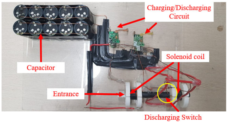
Two methods were used to control the time when the secondary capacitor discharges using physical contact and an optical sensor. The coil gun is shown in Figure 1. The discharge of the primary capacitor results in current flow into the primary solenoid coil, and the projectile is subjected to a force and passes through the tube. For the secondary acceleration of the projectile, a space was created to install a system to control the discharge point between the solenoid coils, as shown in Figure 1. The prototype consists of a discharging switch that uses physical contact with the projectile and an optical sensor that reacts when the projectile reaches the sensing range to control the discharge time.
Components of the two-stage coil gun.
Design concepts of a discharge system using physical contact
Figure 2 shows a diagram of the method used for discharging the secondary capacitor through physical contact. When the charging switch is turned on in the initial state (Figure 2(a)), the capacitor is charged with a voltage (Figure 2(b)). When the projectile reaches the position of the discharging switch and discharges the primary capacitor, the capacitor is discharged due to a collision with the discharging switch (Figure 2(c)). Current then flows through the solenoid coil, and a magnetic field is generated, resulting in a secondary acceleration of the projectile.

Diagram of secondary capacitor discharge using physical contact: (a) Initial state before launch. (b) Charging capacitor. (c) Capacitor discharging. (d) Second acceleration of projectile.
Design concept of discharge system using a sensor
Figure 3 shows a diagram of a two-stage coil gun that uses an optical sensor instead of a switch. In the initial state (Figure 3(a)), the capacitor is not charged because the charging switch is off. The capacitor is charged (Figure 3(b)), where the charging switch is turned on. The projectile reaches the sensing range after discharging the primary capacitor, the projectile is then detected, and a signal is sent to the controller. The controller then sends a signal to the trigger circuit to discharge the capacitor (Figure 3(c)). As a result, the trigger circuit discharges the secondary capacitor, a magnetic field is generated in the solenoid coil, and the projectile is subjected to secondary acceleration (Figure 3(d)).
Diagram of second capacitor discharge using an optical sensor: (a) Initial state before launch. (b) Charging capacitor. (c) Capacitor discharging. (d) Second acceleration of projectile.
Design of two-stage coil gun using a finite element model
Figure 4 shows a diagram of the MAXWELL model using cylindrical coordinates about the Z-axis. The projectile material is Steel 1010 with a radius of 5 mm and a mass of 3.52 g (Table 1). The radius of the tube through which the projectile moves is 6 mm, and the material is aluminum, which has conductive characteristics but is not magnetic. The solenoid coils are wound in the axial direction 14 times and in the radial direction 5 times. The coils have a radius of 0.5 mm, and there is a distance of 4.5 cm between them.
Diagram of two-stage coil gun.
Magnetic properties of steel 1010.

The projectile was positioned at a distance of z1 from the first solenoid coil. When the capacitor connected to the first solenoid discharges, the projectile accelerates with force in the +Z direction. The projectile experiences a second acceleration when the projectile passes between the solenoid coils, and the second capacitor is discharged at a distance of z2 from the entrance of the second solenoid coil. This process continues to change the velocity for a very short period of time, so the analytical method of the simulation was set to transient.
An electrical circuit is also needed to generate electromagnetic force for the acceleration of the projectile. Each solenoid coil is connected to a capacitor. An electrical circuit was constructed using the circuit editor in MAXWELL, as shown in Figure 5. The capacity of the capacitor is 5000 µF, and the charging voltage is 400 V (Table 2). The resistance R was calculated using equation (1). Figure 6 shows the design variables for the solenoid coil, and Table 3 shows the definitions and values for the design variables. The inductance changes with time, but MAXWELL calculates it automatically (Figure 7)


External circuit of coil gun in MAXWELL.
Electronic characteristics.
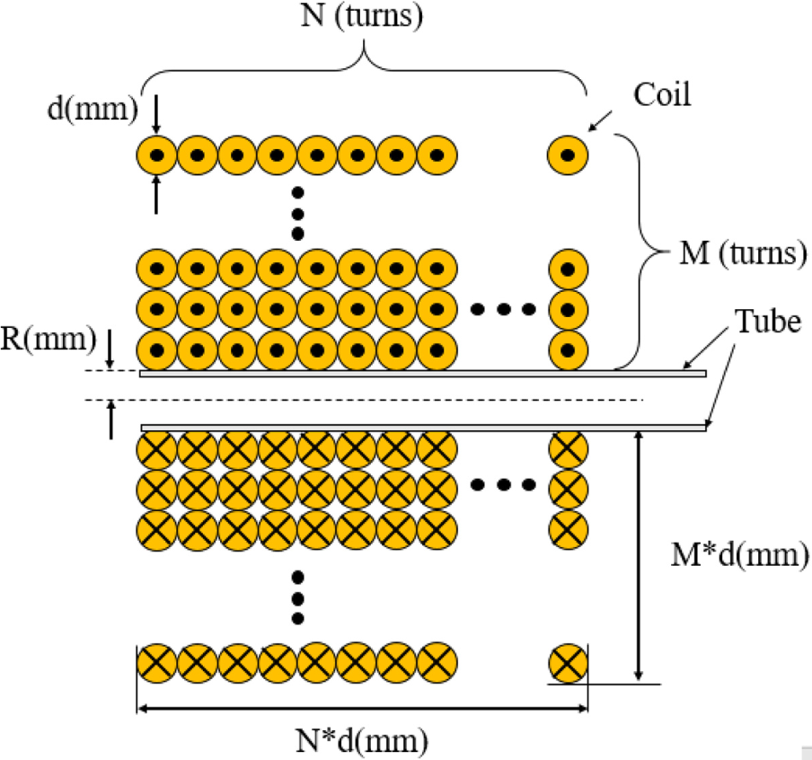
Diagram and variables of solenoid coil.
Specifications of solenoid coils.

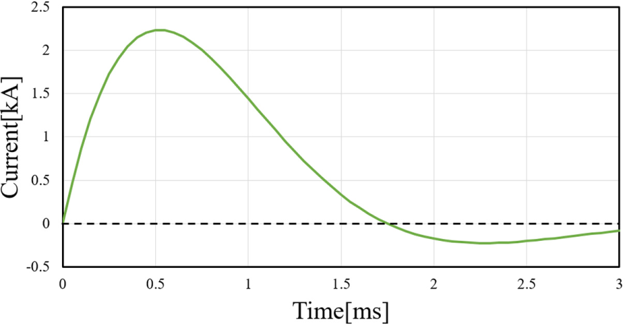
Electric current.
Analysis results of the first stage
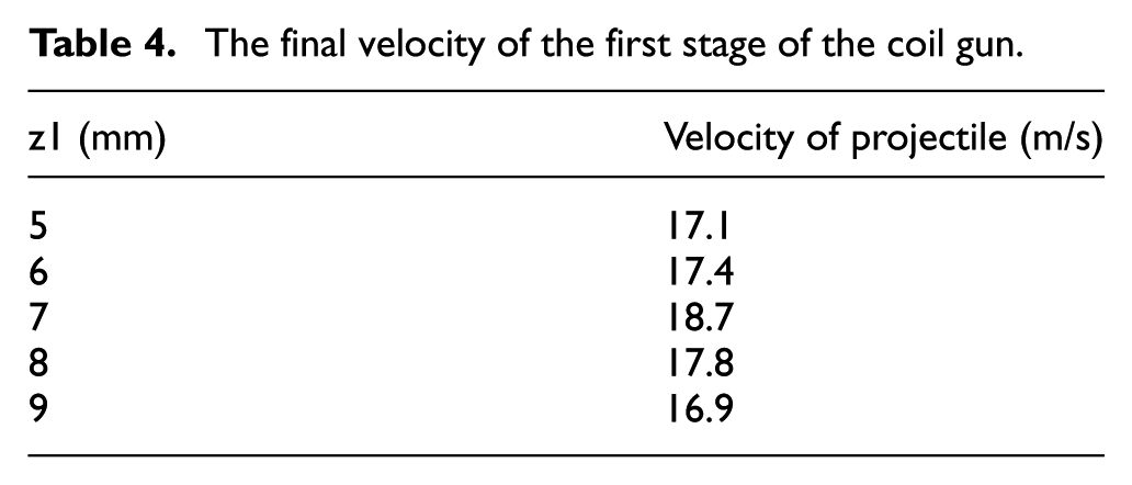
The initial position of the projectile was controlled using MAXWELL to discharge the first capacitor, and the velocity was analyzed over time. Table 4 shows the final velocity of the projectile, according to z1, which is the initial position of the projectile. When z1 is 7 mm, the velocity of the projectile was the highest as 18.7 m/s. Accordingly, the trigger point is determined at the first stage of coil. Figure 8 shows the graph of the current and magnetic force according to time as the projectile pass into the first solenoid coil. The magnetic force is maximum where the projectile is at the entrance point of the solenoid coil at time 1.25 ms and is decreased as the projectile passes into the solenoid coil. Figure 9 shows the velocity of the projectile over time. As the magnetic force acting on the projectile converges to zero from 1.6 ms, it can be seen that there is almost no change in velocity.
The final velocity of the first stage of the coil gun.

Magnetic force and electric current after firing first stage coil gun.

Projectile velocity after firing first stage coil gun.
Analysis result of the second stage
The result of the analysis of the first stage was z1 = 7 mm, which was selected as the initial location for the analysis of the second stage. We used the dataset method for the second capacitor. We entered a value for the current over time in the second solenoid coil when the projectile is located in z2. Because each solenoid coil has the same specifications, the current is the same over time. By using the dataset method, the value of z2 was controlled to derive the velocity value of the projectile over time. Table 5 shows the final velocity of the projectile, according to z2 which is the initial position of the projectile at the second stage of coil. When z2 is 13 mm, the velocity of the projectile was the highest as 26.85 m/s. Accordingly, the trigger point is determined at the second stage of coil. Figure 10 shows the graph of the current and magnetic force according to time as the projectile pass into the second solenoid coil. The magnetic force is maximum when the projectile is at the entrance point of solenoid coil at time 0.4 ms and is decreased as the projectile passes into the solenoid coil. The magnetic force rises again after 1.1 ms, when the projectile exits the coil. Figure 11 shows the velocity of the projectile, and the velocity decreases from 0.75 ms. And it is confirmed to have a constant velocity from 1.75 ms when the magnetic force is not working.
Final velocity of the second stage of the coil gun.

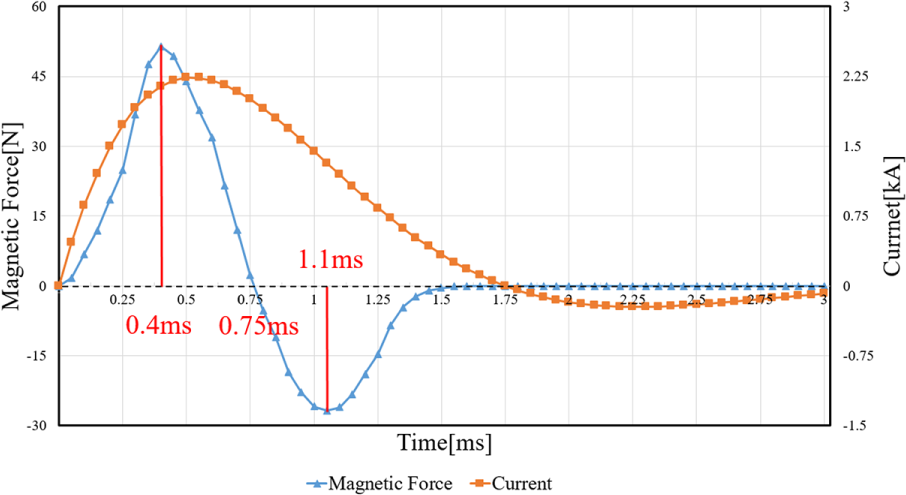
Magnetic force and electric current after firing second stage coil gun.

Projectile velocity after firing second stage coil gun.
Prototype production and results
Using MAXWELL, a prototype was made to verify the simulation results. The X3200 in Figure 12 is a product made by Chronograph. Chronograph creates a velocity measurement device for projectiles or bullets. Using the above product, the projectile velocity of the two prototypes was measured. To control the time when the second capacitor discharges, we designed two discharge systems using a switch and an optical sensor. The prototype of the switch using physical contact was designed to discharge the second capacitor when the projectile contacts the switch. Figure 13 shows a picture of the prototype. The charging and discharging system was implemented using a camera circuit. Figure 14 shows an enlarged view of the area in the yellow circle in Figure 13. After the discharge of the primary capacitor, the projectile comes into contact with the discharging mechanical switch located between the solenoid coils shown in Figure 14. The mechanical switch then rotates in the direction of the arrow so that the discharging circuits are in contact with each other. As a result, the discharge of the secondary capacitor occurs, and the projectile is subjected to secondary acceleration.

Velocity measuring device.
Coil gun with a discharging system using physical contact.

Discharge method of the second capacitor using physical contact.
Figure 15 shows the prototype of a two-stage coil gun that was designed using optical sensor. A camera circuit was used to implement the charging and discharging system. When the projectile reaches the sensing range between the solenoid coils due to the discharge of the primary capacitor, the optical sensor detects the projectile and signals the controller, which discharges the secondary capacitor according to the settings entered in the controller. The secondary capacitor discharges, and current flows into the solenoid coil, which causes the projectile to accelerate for a second time.

Coil gun with a discharging system using optical sensors.
Table 6 shows data of projectile final velocity standard deviation. Ten experiments of each trigger method were performed, which result in the highest final velocity of 24.32 m/s for the optical sensor and 22.57 m/s for the mechanical switch. The highest firing velocity of coil gun with a light sensor is 7.94% higher than the one with a mechanical switch. The final velocity of the projectile is higher when using an optical sensor, but it is necessary to check whether the control is stable. The average final velocity of projectile is 23.005 m/s for optical sensor and 21.897 m/s for mechanical switch. The standard deviation of the projectile velocity of the optical sensor is 1.207, and the standard deviation of the projectile velocity of the mechanical switch is 0.673, which is twice the difference. As a result, it was confirmed that the velocity of the projectile using the optical sensor is far from the average, and the control of the optical sensor is more unstable than the mechanical switch. It probably results from the fact that the optical sensor may malfunction sometimes under experiment condition such as by reactive force from projectile, environmental light, and high temperature in coil under high current.
Standard deviation of projectile final velocity.
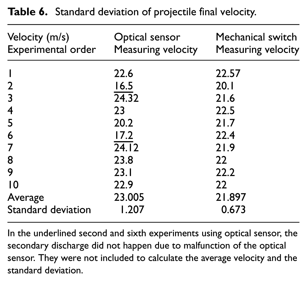
In the underlined second and sixth experiments using optical sensor, the secondary discharge did not happen due to malfunction of the optical sensor. They were not included to calculate the average velocity and the standard deviation.
Figure 16 shows the final velocity of the projectile obtained when using a mechanical switch and an optical sensor. The velocity of the projectile with the optical sensor was 7.6% higher than that obtained with the mechanical switch. This difference is due to friction between the path and the projectile when the mechanical switch is used. It is also believed to be caused by the impact of the contact with the mechanical switch and the time it takes for the mechanical switch to come into contact with the discharge circuit. Furthermore, unlike the simulation, the projectiles are not located in the middle of the tube in the prototypes.

Final velocities of the projectile.
Conclusion
This study compared methods of controlling the discharge system of the secondary capacitor of a two-stage coil gun by physical contact. The coil gun was designed using MAXWELL, and the initial position of the projectile was analyzed to maximize its final velocity. It resulted in the final velocity of 26.85 m/s for a two-stage coil gun. Based on the design values obtained from the simulation, the discharge system was designed using mechanical switch and optical sensor, and the final highest velocity was 22.57 and 24.32 m/s, respectively. The final velocity of the projectile obtained using the optical sensor was 7.6% higher than that obtained with the mechanical switch. However, the optical sensor malfunctions two times of 10 experiments which results in higher standard deviation than that of the mechanical switch. It means that the control of optical sensor provides more sensitive and precise discharge time than the mechanical switch, but the mechanical switch provides more steady control.
As the number of stages increases, the velocity of the projectile increases, and very sensitive optical sensor which is functional in high velocity is needed in the high number of coil stages. It results in high cost and the unexpected risk of malfunction due to experimental condition. On the other hand, the switch using the mechanical contact has a low risk of control since the discharge is generated by the contact between the projectile and the mechanical switch. This switch system has the following advantages: the final velocity fluctuation is small and it has stable control and is relatively inexpensive.
The drawback of the mechanical switch system has time delay due to the operating structure that the projectile contacts the mechanical switch and then the mechanical switch makes the electric discharge on. In the upcoming research, the new operating structure of discharge system using mechanical contact which is more sensitive will be designed and its enhanced performance will be demonstrated.
Footnotes
Handling Editor: James Baldwin
Declaration of conflicting interests
The author(s) declared no potential conflicts of interest with respect to the research, authorship, and/or publication of this article.
Funding
The author(s) disclosed receipt of the following financial support for the research, authorship, and/or publication of this article: This research was supported by Basic Science Research Program through the National Research Foundation of Korea (NRF) funded by the Ministry of Education (2017R1D1A3B03032139) and a Yeungnam University research grant in 2019.