
Abstract
With a 10-kW, 120,000-r/min, ultra-high-speed permanent magnet synchronous motor taken as a prototype, experimental research is conducted on the rotor dynamic behaviours of a three-pad bidirectional gas foil bearing high-speed motor rotor system. Load-carrying properties of the three-pad bidirectional gas foil bearing are analysed, and natural frequencies of conical and parallel whirling modes of the elastically supported rotor are calculated based on an appropriate simplification to the stiffness and damping coefficients of the gas foil bearings. The prototype passes through a 90,000-r/min coast-down experiment. Experiments show that there are violent subsynchronous whirling motions that are evoked by the gas foil bearing–rotor system itself. The cause of shaft orbit drift is analysed, and the corresponding solution is put forward. The theoretical analysis and experimental results can offer a useful reference to the bearing–rotor system design of ultra-high-speed permanent magnet motors and its subsequent dynamic analysis.
Keywords
Introduction
The next generation of propellers and ground power turbines will use oil-free bearings to meet weight and performance requirements. 1 To reduce volumes and weights of machines, some new technologies, such as bearingless permanent magnet machine2,3 and permanent magnet biased active magnetic bearing, 4 are applied to make the machines run at a high speed, but they all require complicated control techniques. As another type of oil-free bearing, gas foil bearings (GFBs) have many advantages such as uncontrollability, high bearing capacity, low friction power, wide working temperature range, impact resistance, low assembly alignment requirements and superior start–stop performance. 5 GFBs have successfully been applied in gas turbines under extreme conditions (DN value > 300 × 104 and 538°C working environment) and have broad application prospects in fields such as fuel cells, distributed power stations, aircraft thrusters and gas processing. 6
Experiments show that subsynchronous whirling phenomena may occur in many GFB–rotor systems. The whirling frequency sometimes varies with the rotational speed, but it is often close to the natural frequency of the bearing–rotor system. 7 For gas bearings without foils (having a stiff surface), owing to the high cross-stiffness, the subsynchronous whirling frequency is nearly twice the rigid critical frequency of the bearing–rotor system. 8 To alleviate or suppress the subsynchronous whirling phenomenon, elastic elements can be used to develop GFBs with large damping. Generally, there are two ways to increase the damping of GFBs: by increasing Coulomb friction damping and by increasing material internal damping. For the former, a multilayer 9 or multileaf10,11 foil structure can be used; for the latter, a metal mesh 12 or a vibration damper component 13 can be introduced. Moreover, three-pad GFBs6,14,15 and three-pad bidirectional GFBs 16 have been developed to further increase the stability of bearing–rotor systems. Research has shown that the stiffness and damping of GFBs are affected by the disturbance frequency, namely, rotor rotational frequency and rotor whirling frequency. At present, there is considerable literature on the calculation of the stiffness and damping coefficients of GFBs; however, few experimental studies focus on GFB–high-speed permanent magnet rotor systems, especially on three-pad bidirectional GFBs. Feng et al. 17 presented rotor dynamic experimental results of a 100-kW, 43,000-r/min, high-speed permanent magnet synchronous motor (PMSM) supported by five-pad multileaf GFBs. Choe et al. 18 presented the experimental results of a 225-kW, 60,000-r/min motor–generator double-span shafting system supported by GFBs. For a 120-kW, 45,800-r/min gas turbine generator supported by GFBs, bearing performances were estimated and dynamic behaviours of the double-span rotor were analysed, and it was pointed out that conical whirling at the turbine end was the main cause of the instability. 19 In the design of GFBs, to some extent, the foil should be flexible. If the foil is too rigid, the amount and rate of deformation of the foil will be weakened, which will decrease material internal damping and Coulomb friction damping, thereby deteriorating the stability of the bearing–rotor system. Therefore, it is necessary to ensure that the foil can generate sufficient deformation under actual service conditions to produce greater damping to absorb the vibration energy of the rotor. In engineering, a single-span rotor supported by GFBs is usually designed as rigid; that is, the working speed of the rotor is lower than the first-order bending critical speed. Because the stiffness and damping of GFBs are very sensitive to rotational speed, if the rotor is not designed properly, rigid mode natural frequencies (cylindrical and conical mode frequencies) of the GFB–rotor system may approach the working frequency, thus causing resonance. Even if the natural frequency of the shaft is lower than the working frequency, it is also possible that the rotor will not be accelerated to its rated speed because of the small bearing damping at a high speed. 20 A feasible solution is to use low-stiffness foils, so that the natural frequency of the shaft can be arranged in a very low speed region where the GFBs have large damping. At present, there are few reports on efforts to employ the above method. In addition, a drift of shaft orbit sometimes occurs in GFB–high-speed motor rotor systems, but the phenomenon has not been reasonably explained in theory.
To test rotor dynamic performance of a three-pad bidirectional GFB–high-speed motor rotor system, we (1) designed three-pad bidirectional GFBs and integrated them into a 10-kW, 120,000-r/min, ultra-high-speed PMSM prototype, (2) conducted speed-up and coast-down experiments of the PMSM and measured the rigid mode natural frequencies and (3) give a qualitative explanation of the drift of the shaft orbit.
GFB design
The test-compliant gas foil journal bearings (GFJBs) were designed in the form of a three-pad structure as shown in Figures 1 and 2. The top and underlying foils are made of Inconel X-750 and 304 stainless steel band, respectively.
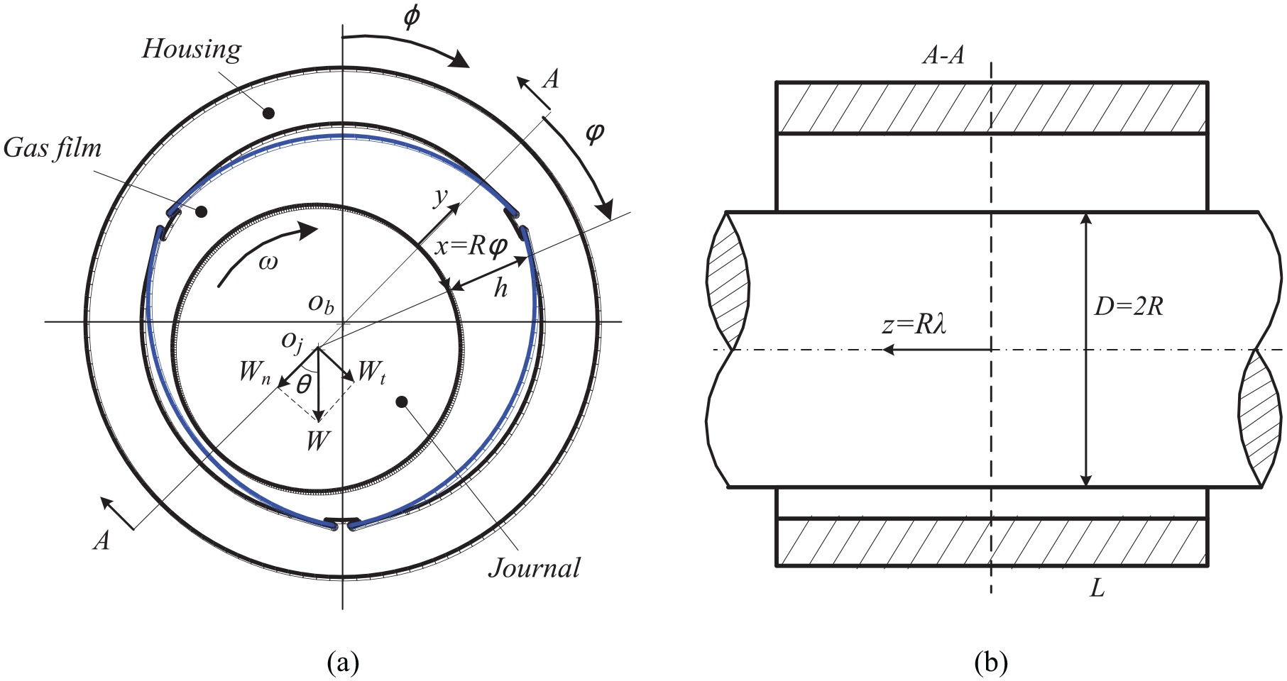
Sketch of the three-pad bidirectional GFB: (a) cross-section and (b) longitudinal section.
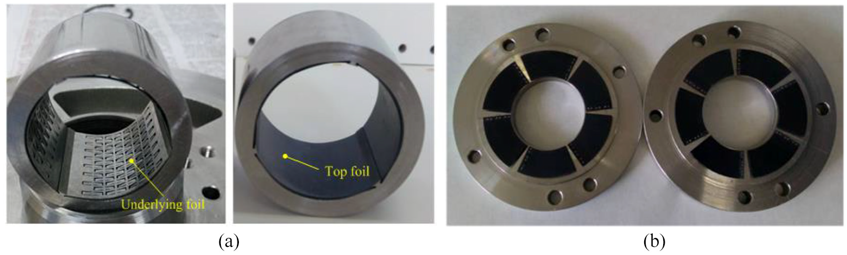
Gas foil bearings: (a) three-pad bidirectional gas foil bearing and (b) thrust foil bearing.
The physical GFJB adopts a three-pad bidirectional structure and the bearing sleeve has six slots, which is shown in Figure 2(a). Once the foil is inserted into the bearing sleeve, radial freedom on both sides is constrained completely; however, a tiny displacement can be allowed in the circumferential direction, as would be the case for a freely supported structure. The bidirectional structure makes the foils robust against being rubbed off by the rotor during preload starting. In the bearing mechanism, the three-pad bearing has three convergent air gaps in the circumferential direction and therefore it will produce three pressure peaks, which make the pressure distribution of the gas film more uniform than for a single-pad circular bearing. In addition, the three-pad structure itself will produce three pre-convergence gaps, and, even though the rotor is not eccentric, it will produce a certain bearing capacity. For the underlying foil, a staggered array cantilever structure is adopted. The structure dissipates the energy by Coulomb friction between cantilever foils and the top foil as well as the bearing sleeve, and also by the vibration of the cantilever foils.
For the gas foil thrust bearings (GFTBs) to be tested, we employed six pads and used a spot-welded structure, as shown in Figure 2(b). One end of the backing bump foils and top foils is welded onto the thrust bearing foundation, and the other end is free to move. To maintain a smooth face of the thrust collar and bearing, the welded spots were polished. A pair of compliant GFTBs was designed to withstand the axial forces caused by the impeller and fan. The geometries of the GFBs are listed in Table 1.
Geometry of the GFJB and GFTB.

GFJB: gas foil journal bearing; GFTB: gas foil thrust bearing.
If the contacts between cantilever foils and the top foil as well as cantilever foils and the bearing sleeve are considered, the calculation will become very complex. Therefore, we ignore these contacts and only consider the elasticity of the top foil, which will be equivalent to a freely supported structure. By fluid–solid coupling analysis, the dynamic stiffness and damping coefficients of the bearing will be obtained. The numerical results for the stiffness and damping performance are shown in Figure 3(a) and (b), respectively. The results indicate that both kxx and kyy increase slowly with the increase of speed and then trend to a certain value; the numerical results for kxy and kyx show that they fluctuate with the increase of speed, but eventually approach 0 r/min. The dynamic damping coefficients decrease with the increase of speed and then converge to zero (as shown in Figure 3(b)). The above results are consistent with those from the literature. 5
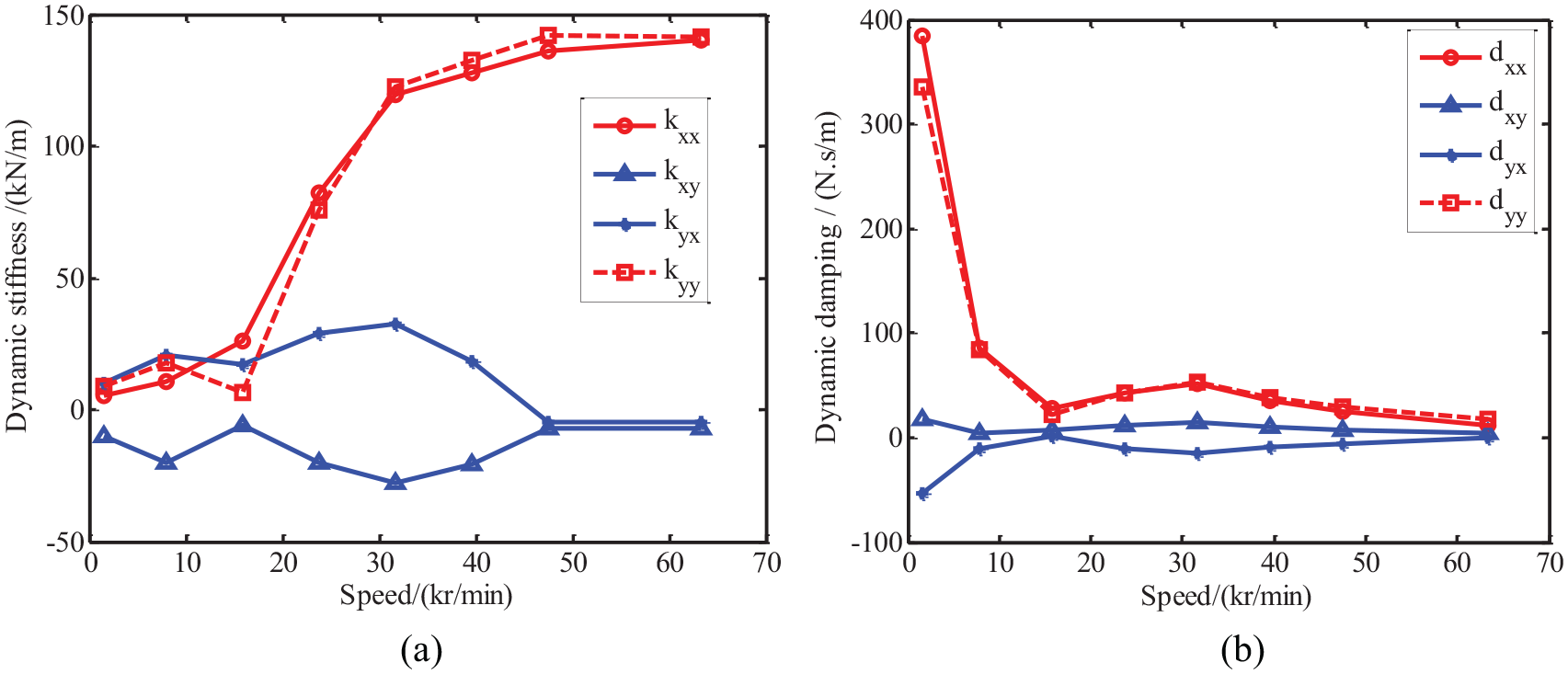
Dynamic stiffness and damping coefficients of three-pad GFBs: (a) stiffness–speed curves and (b) damping–speed curves.
Rotor dynamic analysis
A hammer test was conducted to investigate the first-order bending critical speed of the rotor. The test rig is shown in Figure 4, and the results are illustrated in Figure 5.

Hammer test rig: (a) rotor without impeller and fan and (b) rotor with impeller and fan.

Hammer test of the rotor: (a) test results of the rotor without impeller and fan and (b) test results of the rotor with impeller and fan.
When the impeller and fan were not installed, the first-order bending mode frequency of the rotor was 3140 Hz, which is 57% higher than the designed working frequency of 2000 Hz, as shown in Figure 5(a). After installing the impeller and fan, the first-order bending mode frequency of the rotor was 2661 Hz, which is 33% higher than the working frequency and has a greater safety margin, as shown in Figure 5(b). The hammer experiment demonstrates that the rotor is rigid and meets the design requirements.
A rotor dynamic analysis has been performed using a finite element (FE) model, enabling the rigid mode (conical and parallel modes) frequency to be obtained. The geometrical parameters and material specifications of the rotor without impeller and fan are listed in Table 2. Figure 6 shows the rotor model divided into FEs and the position of the GFJBs.
Geometrical and material properties of the rotor.

PM: permanent magnet.
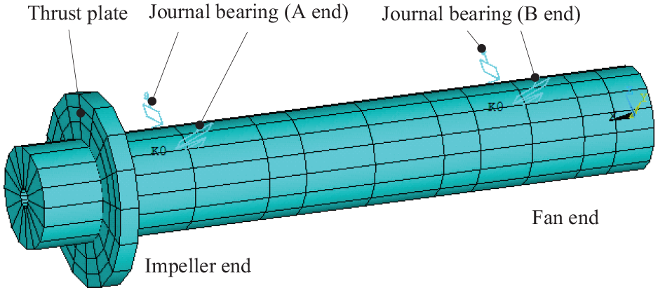
Finite element model of the rotor.
Figure 7 shows a Campbell diagram for the bearing–rotor system obtained using the FE model. The first and second rigid critical speeds were predicted at 4500 r/min (conical mode) and 3500 r/min (cylindrical mode), respectively. The first bending critical speed was obtained at 177,720 r/min (2962 Hz), yet the rated speed of the rotor was 120,000 r/min. Therefore, the rotor rated speed is far higher than the rigid critical speeds and is lower than the bending critical speeds. This indicates that the rotor is rigid.

Campbell chart of the FE model.
Test rig
A test rig was built to demonstrate the running characteristics of the GFB–rotor system. Figure 8 shows the whole test rig, which is composed of a stator, a PM rotor, a set of GFTBs and two three-pad bidirectional GFJBs. In the rotor dynamic experiment, the impeller and fan were not assembled into the rotor. The motor was driven by the frequency converter and cooled by a blower. The motor (rated at 10 kW and 120,000 r/min) was designed independently.
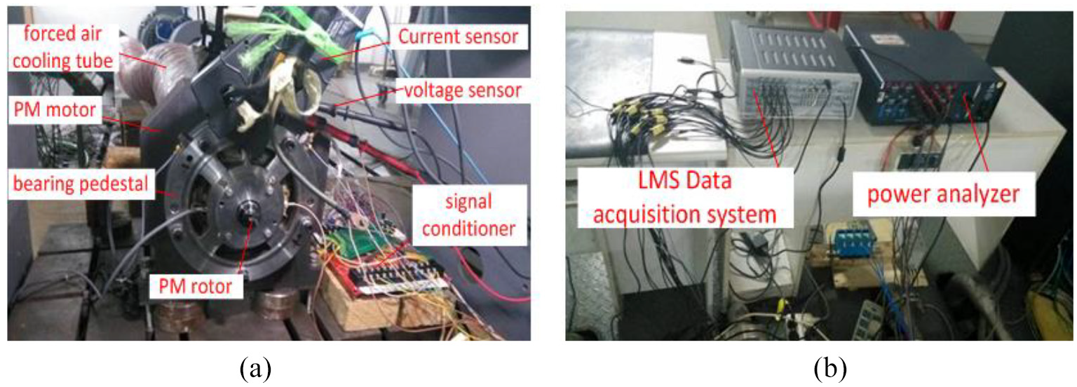
Prototype and measurement system: (a) ultra-high-speed PMSM and (b) signal pickup assembly.
The sketch of the rotor dynamic experimental rig is shown in Figure 9. Horizontal and vertical displacements denoted by x and y at the two rotor ends (impeller end and fan end) were measured by four eddy current displacement sensors. The displacement sensors had a range of 0–0.5 mm, are solution of 0.2‰ and a sampling frequency of 102.4 kHz.

Sketch of the rotor dynamic experiment.
Test results and discussion
A 90,000-r/min speed-up experiment was conducted. The results show that, when the speed increased to the range of 37,439–58,318 r/min, the subsynchronous whirling frequency became dominated by 128 Hz (about twice the cylindrical mode frequency), as shown in Figure 10(a). When the rotor speed increased to 85,437 r/min, the whirling frequency was 160 Hz (about twice the conical mode frequency) and the amplitude of the whirling frequency was smaller than that of the working frequency, so the shaft orbit was still approximately elliptical, as shown in Figure 10(b). When the rotating speed reached 90,000 r/min, it had a 152 Hz whirling frequency whose amplitude was equivalent to or even exceeded the amplitude of the working frequency, and the shaft orbit became petal like, as shown in Figure 10(c) and (d). However, the rotor did not become unstable at 90,000 r/min and could still run continuously. This indicates that the rotor had entered a nonlinear stable region. The above phenomenon in which subsynchronous whirling frequencies are close to twice the rotor rigid mode frequencies may be related to the structural properties of the foil.7,21
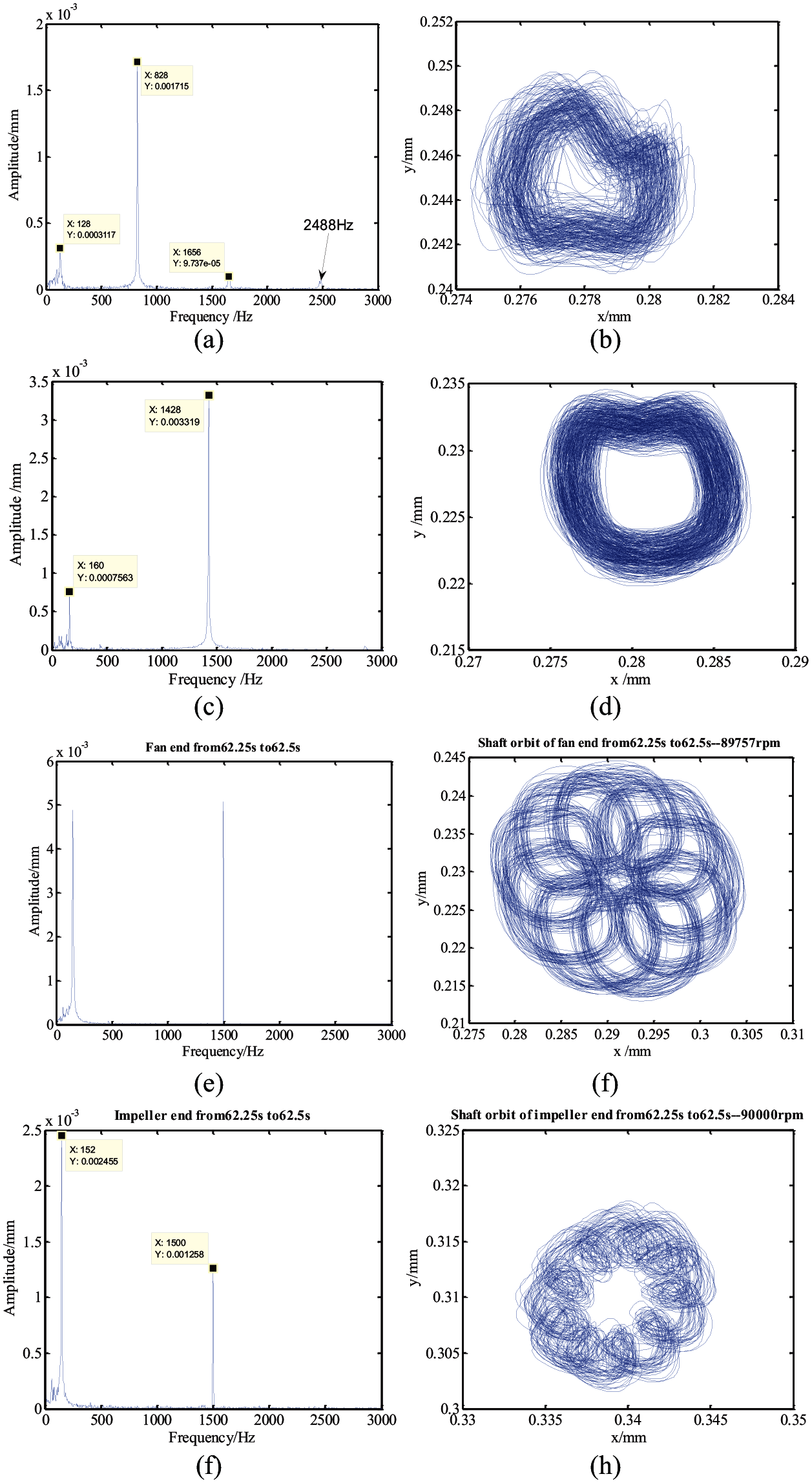
Spectrum and shaft orbit for the 90,000-r/min speed-up test: (a1) spectrum at 50,000 r/min of fan end; (a2) shaft orbit at 50,000 r/min of fan end; (b1) spectrum at 85,000 r/min of fan end; (b2) shaft orbit at 85,000 r/min of fan end; (c1) spectrum at 90,000 r/min of fan end; (c2) shaft orbit at 90,000 r/min of fan end; (d1) 90,000-r/min spectrum at impeller end and (d2) 90,000-r/min shaft orbit of impeller end.
To investigate the source of the subsynchronous whirling mentioned above, a coast-down test at 90,000 r/min was conducted; that is, the frequency converter was turned off when the rotor was stable at 90,000 r/min, and then the rotor speed decelerated to zero by overcoming air friction. In this process, the stator experienced a back electromotive force (EMF), but, because there was no current, the rotor was not subjected to the electromagnetic force. The waterfall chart shown in Figure 11 was thus obtained.

Waterfall chart for the 90,000-r/min speed-up and coast-down test.
It can be seen from Figure 11 that, when the rotor frequency increased to 1500 Hz in 42.5 s, the amplitude of the subsynchronous whirling frequency component suddenly increased, becoming equivalent to the working frequency. At 95.0 s, the frequency converter turned off and the rotor started to coast down. It can be seen that there was still a 140-Hz subsynchronous whirling frequency component until 99.5 s, which indicates that the subsynchronous whirling is caused by the self-excitation of the bearing–rotor system. The peak–peak value of the vertical displacement at the fan end in the coast-down section is displayed in Figure 12.
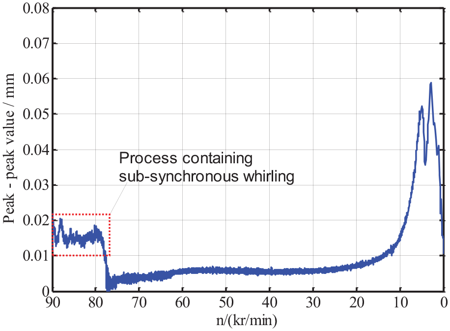
Peak–peak value curve for the 90,000-r/min coast-down test.
Figure 12 shows the peak–peak value curve of the vertical displacement of the fan end in the process of coasting down from 90,000 to 0 r/min, when the frequency converter is turned off. It can be found that the peak–peak value is ∼15 µm in the coast-down test involving subsynchronous whirling. When the subsynchronous whirling disappears (at which the corresponding speed is ∼80,000 r/min), the peak–peak value immediately decreases and remains at the level of ∼5 µm before the speed drops to 20,000 r/min. When the rotational speed continues to decrease from 20,000 r/min, the peak–peak value increases rapidly and there are two obvious peaks, the corresponding frequencies of which are 84.8 and 47.6 Hz, respectively. The rotor modes at the above two frequencies are shown in Figure 13.

Rotor mode according to the peak value of the coast-down test: (a) rotor mode according to 84.8 Hz and (b) rotor mode according to 47.6 Hz.
In general, cylindrical and conical modes are usually concurrent. Previous FE results show that the two rigid mode natural frequencies of the prototype rotor are very close to each other, and then the two modes corresponding to these two frequencies should be excited simultaneously during the coast-down experiment. As shown in Figure 13(a), when the working frequency was reduced to 84.8 Hz, for the shaft orbits at both ends of the rotor, their motion directions were in the same direction as that of the rotation speed. However, the two long axes corresponding to the two orbit ellipses had an included angle of ∼40°, which means that the positive conical mode and the positive parallel mode occurred at the same time. As shown in Figure 13(b), when the speed was reduced to 47.6 Hz, the shaft orbit at the impeller end became enlarged and its rotation direction was opposite to the speed direction, but the rotation direction of the shaft orbit at the fan end was the same as that of the speed. The above situation indicates that a negative conical mode and a positive parallel mode appear simultaneously. The peak–peak value of the shaft orbit at the impeller end is 130 µm reaching the maximum bearing clearance, meaning that the journal had already rubbed against the bearing.
The mode frequencies of the bearing–rotor system are given in Table 3. It can be seen that the conical mode frequency calculated using an FE analysis is close to the experimental result, and the error is 10.5%. The difference may be that, in the FE model, simplified stiffness and damping coefficients are applied, and these are insufficient for accurately describing the actual conditions of the bearings.
Natural frequencies (in Hz) of the GFB–rotor system without impeller and fan.
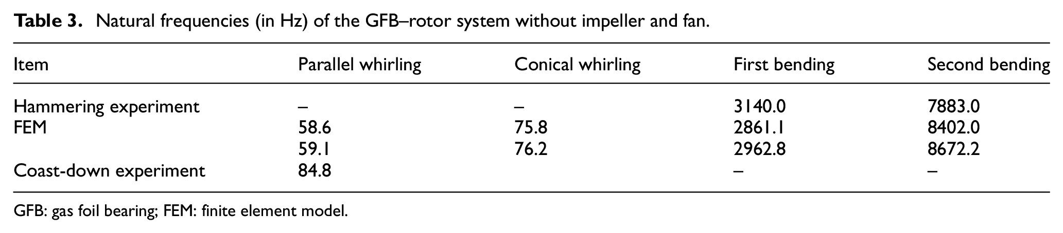
GFB: gas foil bearing; FEM: finite element model.
Experiments also show that shaft orbit drift occurred when the rotor ran stably at different speeds. In this study, a 30,000-r/min comparative experiment was conducted with two different bearing preloads being considered. It is widely known that the bearing preload can be applied by reducing the hole diameter of the bearing sleeve or by inserting the sheet into the foils, and in this study we adopted the former. Two kinds of bearing sleeves with different hole diameters were designed and manufactured. After assembly, the preload moments of the rotor were measured to be 0.1 and 0.3 N m, respectively. The experimental results under a 0.1 N m preload moment are shown in Figure 14. It can be found that both ends of the rotor exhibit shaft orbit drift, and the rotor ran at 30,000 r/min stably from 12 to 222 s. In the process, for the fan end, x and y crawled by ∼13 and ∼12 µm, respectively. For the impeller end, x and y shifted by ∼72 and ∼45 µm, respectively. It can be seen that the drift is more obvious for the impeller end, especially in the horizontal direction.

Shaft orbits under 30,000 r/min and 0.1 N m preload: (a) shaft orbit at fan end and (b) shaft orbit at impeller end.
The experimental results under a 0.3 N m preload moment are shown in Figure 15. It can be found that both ends of the rotor also exhibit shaft orbit drift, and the rotor ran at 30,000 r/min stably from 27 to 87 s. In the process, for the fan end, x and y crawled by ∼72 and ∼22 µm, respectively. For the impeller end, x and y shifted by ∼95 and ∼63 µm, respectively. By comparing Figures 14 and 15, it can be seen that, at both ends of the rotor, the drift in the horizontal direction was larger than that in the vertical direction, and the maximum drift was in x at the impeller end. In addition, for a large bearing preload, the shaft orbit drift phenomenon was more dramatic, which will lead to collision if no safeguards are taken.

Shaft orbits under 30,000 r/min and 0.3 N m preload: (a) shaft orbit at fan end and (b) shaft orbit at impeller end.
According to views A and B in Figure 9, the drift path of the shaft orbits at both ends of the rotor can be drawn, as shown in Figure 16. It can be seen from the figure that the drift of the shaft orbits at both ends of the rotor has the same regular pattern; that is, the steady working point of the rotor moves towards the location corresponding to a greater bearing capacity. It also indicates that the bearing capacity of the bearing continues to decline. One possible explanation is that the gas deliverability of the bearing is insufficient, resulting in deterioration of bearing capacity. Because of gas film pressure, the top foil will deform three-dimensionally, manifesting as an indentation in the middle and a marginal uplift. The deformation can contribute to seal the gas in the bearing to a certain extent; however, it will also hinder gas exchange with the outside. Normally, the high-pressure area of the GFB will force the gas in the bearing to the outside, while the negative pressure area of the GFB will also suck external gas, and then the gas flow rate will reach a dynamic balance. However, if the foil is very soft, its three-dimensional (3D) deformation will be greater, that is, the seal effect will become more significant, which may inhibit external air from flowing into the bearing, so that gas deliverability of the bearing is insufficient and the bearing capacity decreases. The phenomenon is more noticeable especially for a large bearing preload and low-structural-rigidity foils. It is suggested that the drift phenomenon can be eliminated by introducing high-structural-rigidity foils.

Drift tendency of shaft orbits: (a) view A of impeller end and (b) view B of fan end.
Conclusion
In this study, a three-pad bidirectional GFB–high-speed motor rotor system was designed, and a prototype of a 10-kW, 120,000-r/min PMSM was developed using the above scheme. Theoretical and experimental research on rotor dynamics was conducted. The main results are as follows:
The natural frequencies of the rigid mode of the GFB–rotor system were calculated, and a 90,000-r/min coast-down test was conducted. The conical mode frequency calculated using the FE method is close to the experimental result, and the error is 10.5%. The natural frequencies of the rigid mode not only avoid the working frequency of 2000 Hz but also are in the very low speed region. The prototype can reach 90,000 r/min successfully, which demonstrates that the proposed supporting scheme in this study is effective.
Experiments show that, when the rotating speed reaches 90,000 r/min, the whirling frequency is focused in the 140–160 Hz region, the amplitude according to the whirling frequency component is equivalent to or even exceeds the amplitude of the working frequency, and the shaft orbit is petal like. The subsynchronous whirling is caused by the self-excitation of the bearing–rotor system and is about twice that of the rotor rigid mode frequencies.
Experiments also show that shaft orbit drift occurs when the rotor runs stably at different speeds. The ‘seal effect’ caused by 3D deformation of the top foils could be the reason for the above phenomenon because it will lead to an insufficient deliverability of gas. It is suggested that the drift phenomenon can be eliminated by introducing high-structural-rigidity foils.
Footnotes
Handling Editor: Xiaodong Sun
Declaration of conflicting interests
The author(s) declared no potential conflicts of interest with respect to the research, authorship and/or publication of this article.
Funding
The author(s) disclosed receipt of the following financial support for the research, authorship and/or publication of this article: This work was supported by the National Natural Science Foundation of China (Grant Nos 51705413, 51705416 and 11502196) and Chinese Postdoctoral Science Foundation (Grant No. 2017M613291XB).