
Abstract
With the advancement of technology, aiming for achieving a greater lightness and smaller size of 3C products, parts processing technology not only needs to explore the basic scientific theory of materials but also needs to discuss the process of deep drawing numerical and the plastic deformation. This study is based on the square shape of the deep drawing numerical simulation, and aluminum alloy plastic flow stress was input into the finite element method for simulation of plastic deformation in the aluminum alloy friction, mold clamping force, and frequency, as well as amplitude in the influence of forming mechanism and the drawing ratio of aluminum alloy. Finite element analysis software has the function of grid automatic rebuild, which can rebuild the broken grid in the analysis into a complete grid shape, which can avoid the divergence caused by numerical calculation in the analysis process. The greater the obtained error value, the best plastic parameters can be found.
Introduction
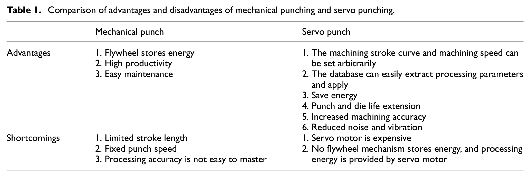
Although the general mechanical punch has the advantages of high energy storage capacity and high production efficiency, it has the disadvantage that the stroke length and the punch speed cannot be adjusted. Although the hydraulic punch can adjust the stroke length and the punch speed, the production efficiency is poor and the hydraulic system is difficult to maintain. Now the industry is actively developing servo punches. The servo control method can meet various conditions in the stamping and is suitable for a small variety of production types. Comparison of advantages and disadvantages of mechanical punching and servo punching is shown in Table 1. 1
Comparison of advantages and disadvantages of mechanical punching and servo punching.
Punching, bending, forming, and extension are the four processing types of sheet metal processing. Recently, due to the fluctuation of raw material prices and low-price competition from developing countries, traditional sheet metal processing industry which has encountered difficulties of cost increase and profit reduction is now under great operational pressure. In order to break through the predicament, the industry should elevate the quality of its products, and develop new products or profit from higher production technologies. Extension forming is one of the most widely used forming methods for sheet metal. The forming method is made of automotive sheet metal, outer casing or front and rear fenders, metal nozzles of aerospace industries, battery casings of 3C electronics industry, micro motors, bullet shells, the outer casing, and so on. However, the use of the extension forming sheet metal is related to many factors such as material properties, product shape, product stress state, and so on.
Figure 1 shows the battery case of 3C electronic products. The depth of the battery case is much larger than that of the other two directions. In the traditional continuous stamping process, multiple passes are required to complete the finished product, and the workpiece has a large amount of rebound deformation as well as poor surface quality. Application of servo punch deep extension forming technology to the battery casing process can effectively improve production yield and the preciseness of the products.
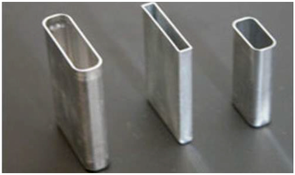
The outer casing of the battery in the 3C product.
In contemporary society, most of the battery casings are mainly aluminum shells and rigid shells. The lithium batteries with the same capacity are lighter than the steel shells because the aluminum shells can be made thinner. Therefore, this study used aluminum alloy 6061 for extension analysis. Stamping processing can be divided into four stages. They are shearing, bending, forming, extension and other items. Various actions have different stamping curves. In the past, the stamping curve of the connecting rod punching machine was determined by different punching machines. The servo punching machine is different from the traditional connecting rod punching machine. The stamping curve can be programmed by the processing requirements. In addition to the adjustability of the stamping curve, another advantage of the servo press is that the stamping process is numerically controlled. The desired stamping curve can be easily set by the computer program setting. 2 This study will discuss the parameters and characteristics of the stamping curve of the die design and the servo punch. The research process is shown in Figure 2.
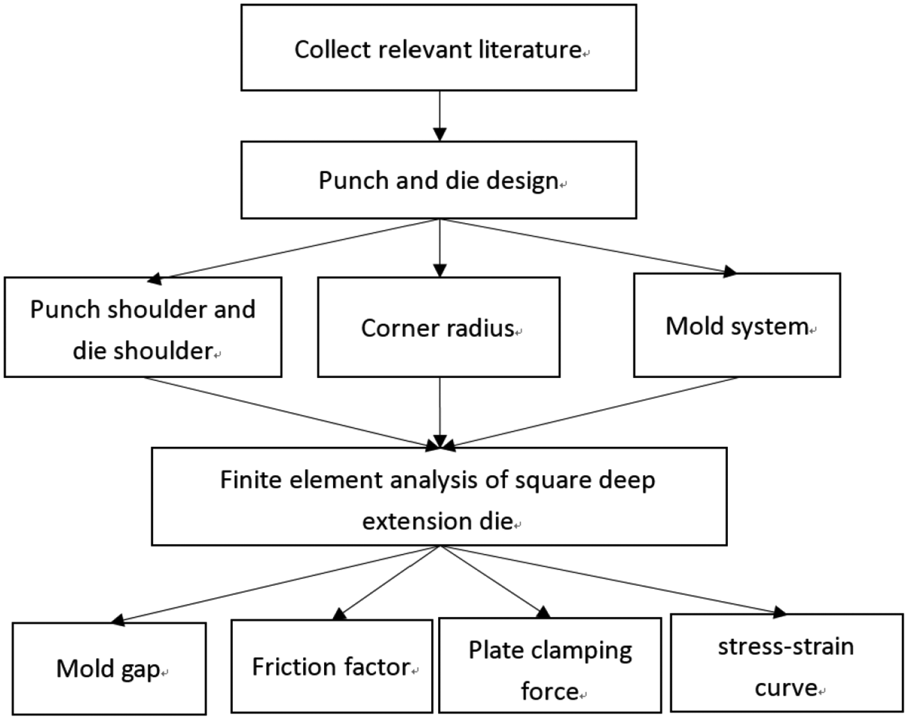
Research flow chart.
Literature
Literature discussion
Mori et al. 3 have used a servo punch to make a V-bending experiment on high-strength steel plates to explore whether different stamping speeds and times can improve the rebound phenomenon, and used the finite element method to simulate the situation where the punches continue to press down the material after reaching the bottom dead center. More specifically, the influence of the die gap on the rebound phenomenon, the high-strength steel plate stamping and forming, and the influence of parameters such as mold material, surface treatment and lubricant selection on the formability were discussed, and the finite element method simulation and experimental verification were used. Wu 2 mentioned that if the plastic deformation is microscopically, which meant that when the metal was subjected to an external force, causing the stress to exceed the metal stress, the lattice was distorted, and a part of the crystal was generated along another crystal plane for another part. Relative sliding, after the sliding was generated, the external force was removed, and the deformation of the crystal could not be completely recovered.
Manabe et al. 4 have proposed the interaction between the extension speed and the pressing force, having simulated the wrinkling and rupture of the metal material during the extension process, having analyzed the thickness distribution of the finished product, and having defined the range value of the wrinkle, indicating that the extension was related to the extension speed and the pressing force. Liu 5 mentioned the reason for improving the formability of the servo punch curve. In the simulation, the friction condition was set as the friction coefficient changes with the stroke of the punch, and in the rising phase of the curve, the friction coefficient would decrease, and finally the material was simulated. The thinnest thickness was used as the basis for judging the formability. The simulation results showed that under the conditions of double-sided lubrication and single-sided lubrication, the thinnest thickness was improved compared with the pulse-free curve. Therefore, the simulation proves that the pulse-wave curve is improved by the effect of relubrication.
Jiang 6 studied the extension ratio as a measure of the deformation index of micro-extension forming materials. The appropriate extension ratio could reduce the phenomenon of extension and generation of wrinkles and cracks. In Han’s 7 experiment, the friction between the plate and the mold directly affected the fluidity of the plate during the forming process, which in turn affected the formability. It was recommended to reduce the friction between the plate and the lower die and the pressure plate, and moderately increased the friction between the plate and the punch to slow down the thinning of the mold and the sidewall. Controlling the width of the truncated angle could effectively improve the formability of the panel at the corner of the mold. Singh and Agnihotri 8 examined the combination of deep extension quality process parameters as a way to keep defects to a minimum. In this study, the coefficient of friction varied from 0.2 to 0.07. The effect of friction coefficient on thickness variation was investigated. By examining the thickness, it was possible to evaluate the thinning tendency of the R angle area of the mold and the radius area of the punch. The results showed that as the friction coefficient decreases, the thickness distribution of the entire part was significantly improved.
Lang et al. 9 have tested the aluminum 1050 H0 and 6016 H4 sheets to reach the extension ratios of 3.11 and 2.46, respectively, and explored the influence of different pressure paths on the thickness distribution of the finished cup wall, which was consistent with the finite element method simulation results. Afterward, the radial pressure deep extension forming method was combined with the experiment to explain the three types of failure and failure modes in the initial, middle and final stages of forming, and the pre-expansion pressure, the in-mold pressure, the sheet material, and the lower mold gap were compared with the limit extension ratio of the product. Witulski et al. 10 have used deep extension with a polymer body which enhanced the complex shape of the layer and hard coat layer was obtained by indirect spraying. Leu 11 found that plastic instability was defined by the measurement of the ultimate extension ratio. Xu et al. 12 have discovered that the complex recovery behavior of a laminate undergoing a tensile bending process was depending on the operation and material parameters.
Research method
Battery square aluminum mold design
In the extension processing of designing a square container, if the radius of the corner portion is reduced, the corner portion is increased, and the difficulty in the deformation of the extension processing is increased. 13 But not necessarily, this will reduce the limit of extension processing. When the radius of the corner portion is reduced and the straight side portion is increased, the corner portion is subjected to contraction deformation, and it is easy to flow out to the straight side portion. Therefore, the amount of contraction deformation was substantially reduced, and the elongation resistance of the drawing processing was alleviated. In the extension processing of the corner cylinder, the curved portion of the square corner had the same deformation as that of the extension of the cylinder, and the straight portion was only subjected to the bending process, and therefore, it was considerably more difficult than the extension processing of the cylinder. For the extension processing of the stability, the radius of the four corners must be about 20% of the extension depth, and the radius of the corner of the punch and the corner radius of the die shoulder were at least 10 to 15 times the thickness of the plate. Figure 3 shows the battery square mold design.
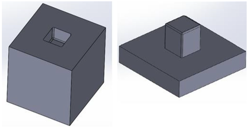
Battery square mold design.
Punch impulse
The punching force was required for the deep drawing apply on the flange and the shoulder material to resist the frictional resistance of moving tools, and the sum of the shoulder bending resistance. The Pmax (N) is deep drawing cylindrical container maximum punching force. It was necessary to obtain the maximum punch momentum from the tensile deformation of the cylinder

where
Flange crimping plate
During the extension process, the outer edge of the aluminum alloy billet was pulled into the punch, and the amount of compression and thickening was larger, and because the metal was pressed, it tended to wrinkle and was not easily compressed, especially in thin pieces or deep. The extension was particularly obvious, so the wrinkle force should be minimized in the range where the flange wrinkles did not occur. The minimum pressure to suppress flange wrinkles is increased with deep drawing ratio. The smaller the thickness and the greater the deformation force of the material was, the more necessary the minimum crimping force was required. The minimum crimping force required to extend the cylindrical container was determined by this experimental formula

where
Punch and die gap
If the side wall of the molded product was stretched and the gap was increased by a small amount, the ironing phenomenon might occur. The increase in the thickness of the side wall varied depending on the material or the ratio of the stretching process. If it was molded without ironing at all, the general gap was 1.5 times the thickness of the plate. Ironing was to apply the material to the ironing resistance to increase the impact effect, and the other side could also prevent the breaking force from being generated between the punch and the material. Therefore, the ironing space with the maximum extension limit had the most suitable amount of clearance.
Punch fillet radius
When the fillet radius of the punch was smaller than the thickness of the punch, the bending resistance would increase, which not only causing the increase of the punch’s impulse but also increasing the thickness of the bent portion, resulting in easy cracking and rushing. The excessive radius of the fillet of the head would also increase the portion which was not restrained by the flange crimping plate, so that the sidewall wrinkles of the blank were prone to occur. Therefore, in order to prevent the occurrence of wrinkles, it was preferable to use the recommended values in the following ranges

Female die shoulder fillet radius
For the undersized parent mold die shoulder fillet radius, the plate was prone to cracking; as for the oversized parent mold shoulder fillet radius, at the end of the processing, the edge of the plate was detached from the pressed wrinkle, resulting in easy wrinkles. The deformation of the shoulder of the punch, because the deformation was completed at the beginning of the stroke of the punch, did not affect the impulse of the largest punch. When the radius of the shoulder of the female die shoulder was too large, the influence of the biaxial tension deformation at the bottom of the punch would increase the thickness of the plate, and when it was too small, the thickness of the plate would decrease due to the bending deformation. It was easy to form a break. Therefore, the recommended value for the range shown below was excellent

Finite element analysis
Square element finite element analysis
First, computer-aided engineering analysis was carried out to simulate the deep extension process of the aluminum alloy casing of the battery, and according to different process parameters, such as mold fillet, pressing force, mold gap and friction coefficient, it was found that the suitable ratio was not broken. Finite element analysis methods such as DEFORM, ANSYS, and DYNAFORM were used in metal plastic forming. Deform can be used to predict and analyze the stress, strain, flow velocity, and other information of the deformation of the billet, and the simulation results can be used as the mold development with relevant design or manufacturing experience. References can improve many mold designs and process defects, reducing the time and cost of trial and repair molds. 3 In this study, the square shape of the battery was numerically simulated by deep extension, and the optimal aluminum alloy plastic flow stress was input into the finite element method to simulate the friction force, mold clamping force, and frequency of the aluminum alloy during the plastic denaturation process. How does amplitude affect the forming mechanism and optimize the aluminum alloy’s drawing ratio? The finite element analysis can re-establish the mesh broken in the analysis into a complete mesh shape, which can avoid the divergence behavior of the numerical operation during the analysis process.
The CAE extension analysis uses the finite element analysis software to simulate the deep extension of the square tube. The process parameters that can be set on the analysis software are (1) punch speed, (2) billet temperature, (3) mold temperature, (4) material of the billet, and (5) coefficient of friction. The geometric parameters of the mold are an important part of the influence of the extension forming. In this set of simulation software, the geometric parameters of the mold were set by the CAD software in the drawn mold, such as the mold R angle. In the simulation mold design, only the forming part was considered, because in the finite element analysis software, the mold was set as a rigid body, and that’s the reason why when the mold was designed by using CAD, only the formed part was considered, and the overall strength of the mold was not. In this study, the square tube extension was used to establish the extension ratio and the extension shape parameters. Therefore, the R angle design was adopted in the mold cavity setting.
Extension speed and pressing force
Manabe et al. 4 have studied the extension speed and the pressing force proposed by the research institute to simulate the wrinkling and rupture of the metal material during the extension process, analyze the thickness distribution of the finished product, and define the range value of the wrinkle, indicating the extension condition and the extension speed and the pressing force. The servo punch curve was discussed to improve the formability. 14 In the simulation, the friction condition was set as the friction coefficient changes with the stroke of the punch, and in the rising phase of the curve, the friction coefficient would decrease. Finally, the thinnest thickness after material simulation was used. The simulation results showed that under the conditions of double-sided lubrication and single-sided lubrication, the thinnest thickness—the basis for judging formability—was improved in comparison with the pulse-free curve.
Servo punch curve simulation
Analysis of the motion curve of servo punch
The servo punch curve is discussed and experimented. The computer-assisted engineering analysis is used to simulate the servo motion curve. The simulation of deformation, stress, strain distribution, and fracture situation is discussed. Then, the servo casing is used to carry out the deep extension forming of the square shell aluminum alloy. For materials, in the tensile test, different stretching speeds will correspond to different elongations; in this case, it can also be seen in the metal extension processing, and the extension results will be different at different extension speeds. In general, the slower the strain rate of the metal, the better the tensile results. Therefore, this experiment used a constant velocity extension curve and tests at different extension speeds. It was expected to be the same as the tensile test. At speed, a larger extension depth could be obtained, which was achieved by servo punching and to find the relationship between speed and maximum depth of extension. After finding the extension depth that can be achieved at each speed, the changes of the billet during the extension process will be analyzed, and the hypothesis proposed in this article will be supported by the mechanical point of view.
Constant speed extension drawing stamping curve planning
The punching curve of most traditional punching machines is a constant speed extension curve. Although the traditional punching machine cannot change its curve characteristics, the punching speed can still be adjusted. The most important part of the drawing curve of the drawing process is the extension zone where the punch and the test piece are in contact. The parameters of this part including the extension speed and the target depth of the extension, and the target depth has been determined. Therefore, only by obtaining the extension speed, the stamping curve can be drawn, and the shape of the mold for processing and the test piece material are first analyzed for the extension capacity at various speeds and the relationship between the extension speed and the extension capacity is plotted, as shown in Figure 4. When the target depth of the extension is determined, the extension speed corresponding to the depth on the map is found, and the stamping curve can be determined. The stamping curve defined by this method has the highest speed per minute (SPM) without wrinkles and cracks. The speed is drawn to the drawing curve.
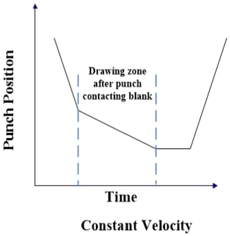
Fixed-speed extension drawing curve.
Variable-speed extension stamping curve planning
The variable-speed extension curve is the only action that can be achieved by the servo punch. The process of attracting the extension is according to the change of the punching pressure during the extension, and the method of changing the speed of the extension curve to try to reduce the probability of rupture, as shown in Figure 5. In the front section, it is not easy to cause the blank to be pulled off. The faster extension speed can be applied first, so that the thermal effect generated by the test piece during the faster extension of the section increases the temperature, thereby improving the plasticity of the metal. Thus reducing the deformation resistance, in the rear section; the deformation resistance at the flange of the test piece begins to rise. So the punch speed is gradually reduced to reduce the stress, and the deeper the extension depth, the smaller the punch speed should be lowered.
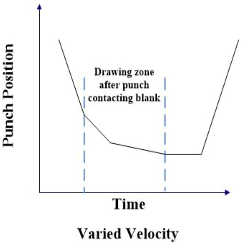
Variable-speed extension stamping curve.
Planning method of vibration-type extension stamping curve
The shock-type stamping curve is different from the variable-speed curve, as shown in Figure 6. The curve of the constant speed extension was formed by adding a sine wave to the extension section. The characteristic of this curve was that the punch was constantly vibrating, so that the temperature of the test piece rose during the process of deformation and rebound, softening the metal, and making the test piece. The ductility rose and the test piece was easily relieved of stress due to back and forth vibration.
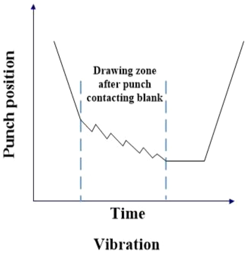
Vibration-type extension drawing curve.
Results and discussion
Simulation analysis of the size design of circular aluminum alloy mold
Simulations were conducted using the rigid-plastic finite element method with 6061 aluminum materials. This study made the following assumptions: (1) the mold, die, and punch are all rigid bodies and (2) the aluminum alloy (AL-6061) is a right plastic material. This study used a given velocity profile extension stamping circular aluminum mold planning simulation design size—DEFORM simulation. The thickness of the test piece is 5 mm, as shown in Table 2. Find the stress, strain, and flow velocity of the aluminum alloy during plastic deformation.
Round aluminum alloy mold size.

DEFORM software analysis circular aluminum alloy set data grid number 32000, material AL-6061-T4COLD (20°C), friction force 0.12 N, and extension constant speed 2 mm/s. The stress is the internal force of the material subjected to external force, the internal force is resisted, and the internal force per unit area; the circular extension die simulates the stress distribution diagram, as shown in Figure 7. The highest strain is 9.19 mm/mm; the strain is the force applied by the material, the deformation amount per unit length or unit volume; and the strain distribution diagram of the circular extension die is simulated, as shown in Figure 8. The highest flow velocity is 5 mm/s, and the circular extension die simulates the flow velocity profile, as shown in Figure 9.
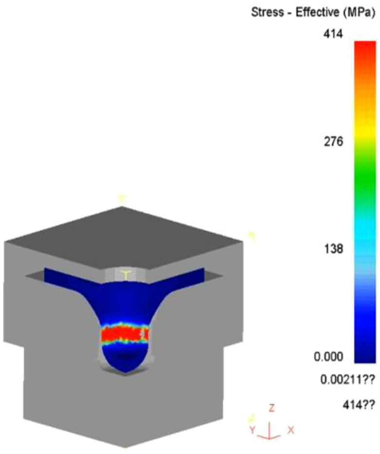
Circular extension die simulation analysis effective stress distribution map.
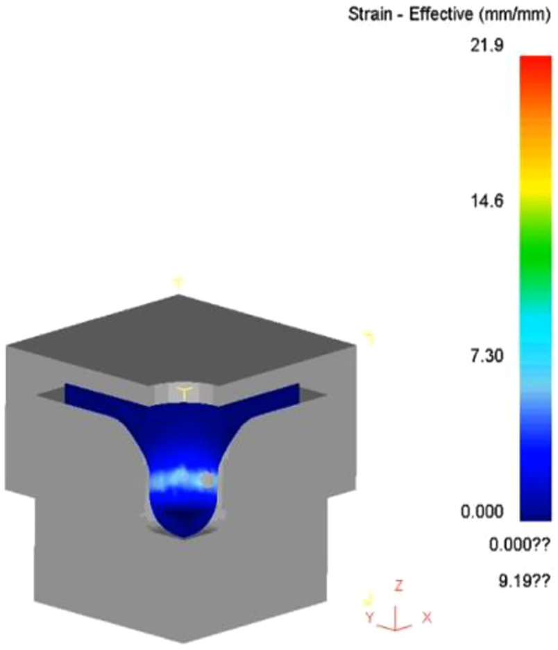
Circular extension die simulation analysis effective strain distribution diagram.
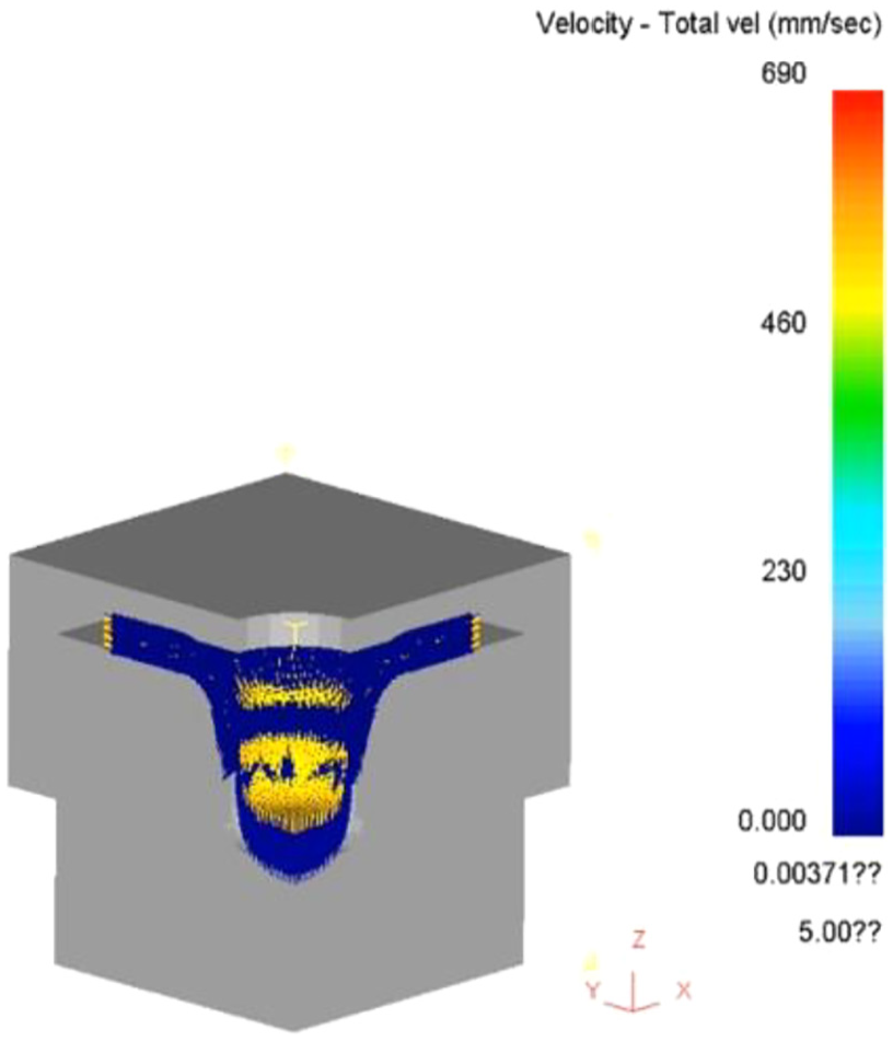
Circular extension die simulation analysis flow velocity distribution map.
Simulation analysis of square aluminum alloy die size design
The dimensional design of the square aluminum alloy mold was analyzed by DEFORM, and the thickness of the test piece is 5 mm, as shown in Table 3. Find the stress, strain, and flow velocity of the aluminum alloy during plastic deformation.
Square aluminum alloy mold size.

DEFORM software analysis square aluminum alloy setting data grid number 32000, material AL-6061-T4COLD (20°C), friction force 0.12 N, extension constant speed 2 mm/s, and the highest stress 617 MPa; the square extension die simulates the stress distribution diagram, as shown in Figure 10. Figure 10 shows the material fracture caused by the tensile force of the material beyond the deformation. The highest strain is 13.5 mm/mm, and the square extension die simulates the strain distribution diagram, as shown in Figure 11. The highest flow velocity is 5 mm/s, and the square extension die simulates the flow velocity profile, as shown in Figure 12.

Square extension die simulation analysis effective stress distribution map.

Square extension die simulation analysis effective strain distribution map.

Square extension die simulation analysis flow velocity distribution map.
Conclusion
There are many factors affecting the cracking of the finished product in the square aluminum alloy extension die process, which may come from each curve parameter of the servo punching machine, the nature of the material, the design of the mold, the structure of the product, the frictional force in all directions, and so on. It is possible to cause the rupture of the finished product. In this study, we will further investigate the servo punching parameters adjustment with the best mold design. First, we will collect relevant servo punching parameters and material literature, and set up the factors that mainly affect the extension and rupture in the literature. The finite element analysis software DEFORM is simulated with different molds of circular and square shape, and the square aluminum alloy mold design is set with the circular data experience reference. The optimal mold design is set by the analysis result, and the simulation results show that the rupture is extended. After the subsequent improvement of its factors, the mold is opened and actually verified on the servo press with different curves.
Footnotes
Handling Editor: James Baldwin
Declaration of conflicting interests
The author(s) declared no potential conflicts of interest with respect to the research, authorship, and/or publication of this article.
Funding
The author(s) disclosed receipt of the following financial support for the research, authorship, and/or publication of this article: The authors gratefully acknowledge the financial support of the Ministry of Science and Technology of the Republic of China, Taiwan, under Grant No. MOST 107-2622-E-110-006-CC2.