
Abstract
In the deep drawing process, achieving a higher drawing ratio has always been considered by researchers. In this study, a new concept of hydrodynamic deep drawing with two consecutive stages without additional operations such as annealing is proposed to increase the limit drawing ratio of the cups. The effective parameters were investigated numerically and experimentally in the forming of Al1200 cylindrical cups. At first, the desired value of punch diameter ratio was determined based on finite element simulation results and was utilized to increase the cup formability. Next, the effects of pressure paths on the cup thickness, separation, and rupture were studied in each forming stage. The cup formability was investigated based on a new proposed framework to obtain the maximum possible limiting drawing ratio, and the desired conditions were determined. Finally, a cup was formed with a high drawing ratio of 3.4 which was a good achievement in comparison with the literature.
Keywords
Introduction
The sheet hydroforming process has a wide range of applications in automotive, aerospace, etc, and has many advantages over conventional deep drawing.1–5 In recent years, hydrodynamic deep drawing assisted by radial pressure (HDDRP) has given good results in the forming of parts with a higher limit drawing ratio. In HDDRP, the blank is formed on the surface of the punch by the pressurized liquid in the die cavity. Meanwhile, the liquid flows out dynamically which leads to a uniform pressure on the blank outer edge. Many other advantages are obtained by using this process, such as high dimensional accuracy, good surface quality, and production of complicated parts.2,6
Lang et al. 2 investigated the forming of Al6016-T4 aluminum alloy in the HDDRP process experimentally. They studied and predicted the fracture and wrinkling of cylindrical cups. Finally, they formed the cylindrical cup with the maximum drawing ratio of 2.46 from a 1.15 mm thick sheet. Hashemi et al. 7 investigated the HDDRP forming of conical parts numerically and experimentally. They determined the process window diagrams (PWDs) to compare Al1050/St14 laminated sheet and its constituent single layers. They redefined the limiting drawing ratio (LDR) of a conical cup in three forms depending on cone angle, tip radius, and cup height to investigate the effects of those parameters under similar conditions. They obtained various values of drawing ratios for different LDR definitions from 3.12 to 9.9. Hashemi et al. 8 developed a new optimization procedure by an adaptive combination of simulated annealing optimization algorithm and finite element method to predict the optimal pressure load in hydrodynamic deep drawing (HDD) of bilayer composite cups. Salahshoor et al. 9 investigated the effects of several HDDRP parameters on punch force and thickness distribution of pure copper cylindrical cups with a drawing ratio of 1.9 numerically and experimentally. Khademi et al. 10 modified the HDDRP with inward flowing liquid. Also, they studied the effect of controlling radial pressure and the cavity pressure on thickness distribution numerically and experimentally. Bhatt and Buch 11 developed an expert system to design a die for multi-stage deep drawing (MSDD) operations to improve quality and productivity. Pourkamali et al. 12 studied the MSDD of an industrial part with annealing between steps. Zhu et al. 13 proposed the multi-stage HDD to form a stainless-steel cup with complex stepped geometries. They stated that it is difficult to manufacture the part in a single HDD stroke due to the large unsupported areas of the blank between the punch and the die and also the small corner radius which can lead to wrinkling and tearing. So, the elimination of the defects needed a multi-stage HDD process. They investigated the effect of pre-form depth on the final products and could obtain a drawing ratio of 4 with a 0.4 mm thick stainless steel sheet. Li et al. 14 put forward a multi-stage HDD process to study the precision of deep conical parts. They stated that forming a desired conical part with a single deep drawing process is difficult due to the large deformation and the high drawing ratio. Also, they explained that the control of defects such as wrinkling and tearing in the multi-stage HDD process is difficult contrary to the single HDD process. Thus, it is crucial to investigate the defect pattern and parameters interaction for controlling the forming quality. Accordingly, they examined the sequential deformation of a conical part using theoretical and numerical analyses and experiments. They formed a conical part with a drawing ratio of 3.7 from the 2024O aluminum alloy sheet with a thickness of 1 mm.
In the deep drawing process, getting a higher drawing ratio as well as less production time with the desired quality has been always considered by researchers. Oluwole et al. 15 investigated the drawing ratio in conventional deep drawing of fully annealed Al1200 sheets with different thicknesses of 0.6–2 mm. They formed a cylindrical cup with a maximum drawing ratio of 1.87 for 1.55 mm sheet thickness. Li et al. 14 formed a conical 2024-O aluminum cup from an initial blank with 1.0 mm thickness and 96.5 mm diameter with a maximum drawing ratio of 3.7. Zhang et al. 16 were able to reach a drawing ratio of 2.5 and 2.6 for Al1100 and mild steel (A-K steel) cups, respectively from 1 mm thick blanks using the hydromechanical deep drawing. Lang et al. 17 formed cylindrical cups with the maximum drawing ratios of 2.46 and 3.11 for a 1.15 mm thick Al6016-T4 and a 1.24 mm thick Al1050-H0, respectively by hydromechanical deep drawing.
In this study, a novel two-stage hydrodynamic deep drawing process (TS-HDD) based on the HDDRP process in only one die set was utilized to achieve a higher drawing ratio. It is worth noting that the forming of a similar cup by a conventional deep drawing process requires an increase in the number of forming stages in several separate dies. Also, in most cases, additional operations such as annealing or redrawing are required between successive stages. The proposed TS-HDD design in this research improved the limiting drawing ratio using only one die set in two consecutive stages without additional operations. This will cause a reduction of production time and tooling cost compared to the conventional deep drawing process. The most important feature of this new design is the use of only one die set with two coaxial punches and a stepped pressure chamber instead of several separate dies. This feature reduces the number of drawing stages compared to the conventional deep drawing and causes a consecutive forming without moving the part between different dies. Therefore, it is crucial to investigate the defects and the process parameters to achieve a high-quality part with a high drawing ratio. So, the effects of parameters on rupture and thickness distribution have been discussed in the TS-HDD using FE simulations and experimental tests.
Material and methods
In this research, first, a method for determining the appropriate diameter ratio of the punches was studied. Then, the desired pressure paths and maximum values at each stage were investigated separately. A new framework was proposed considering a two-stage consecutive process to determine the obtainable maximum drawing ratio in TS-HDD. Finally, a cylindrical cup was formed with a high “drawing ratio” and high “height to diameter ratio” by the TS-HDD process under the desired working conditions obtained from investigations.
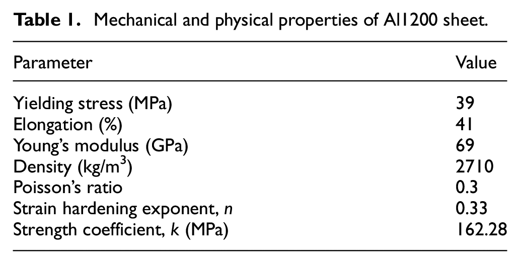
A 1.5 mm thick Al1200 sheet fully annealed at 350°C for 120 min was used. Round blanks were cut from aluminum sheets. Standard tensile tests according to ASTM-E8M were performed at three rolling directions of 0°, 45°, and 90° to obtain the mechanical properties. The material properties and the true stress-strain curve of the material obtained from the tensile tests are given in Table 1 and Figure 1, respectively.
Mechanical and physical properties of Al1200 sheet.
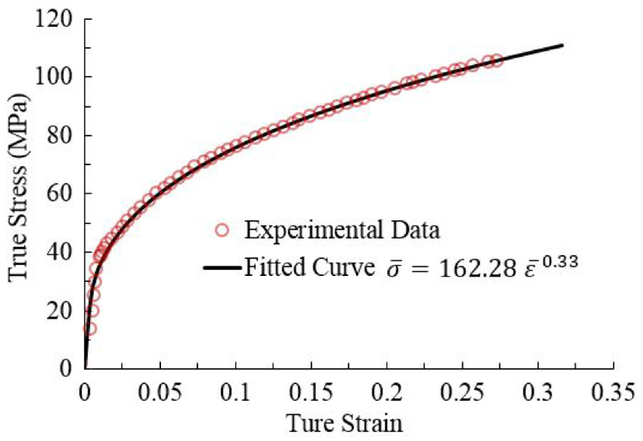
Stress-strain curve of Al1200.
Figure 2(a) shows a schematic of the TS-HDD process and the die parametric dimensions. The main components consist of two coaxial punches (primary and secondary), metal blocks, a blank holder, and a stepped pressure chamber. Based on the nature of the hydrodynamic process, no sealing is used in the process. In the TS-HDD for each stage, the oil leaks out dynamically from the contact surface of the blank holder and the die. The interface between the die and blank holder was ground metal contact and no o-ring was used for sealing in the die (region g in Figure 2(a)). In stage one, the leaking liquid creates pressure under the blank and around its rim at the same time as in the HDDRP process. In stage two, the hydrodynamic process occurs by small leakage of liquid from the blank holder/die interface like the first stage, but the pressure is created on the outside and the edge of the pre-formed cup. Also, an initial pressure of 2 MPa was exerted before the movement of the punches at each forming stage. The SAE 20/5.6 cSt hydraulic oil was used in the experiments. Figure 2(b) shows the assembled TS-HDD die set installed on the press machine. The experiments were performed using a 150 kN hydraulic press.
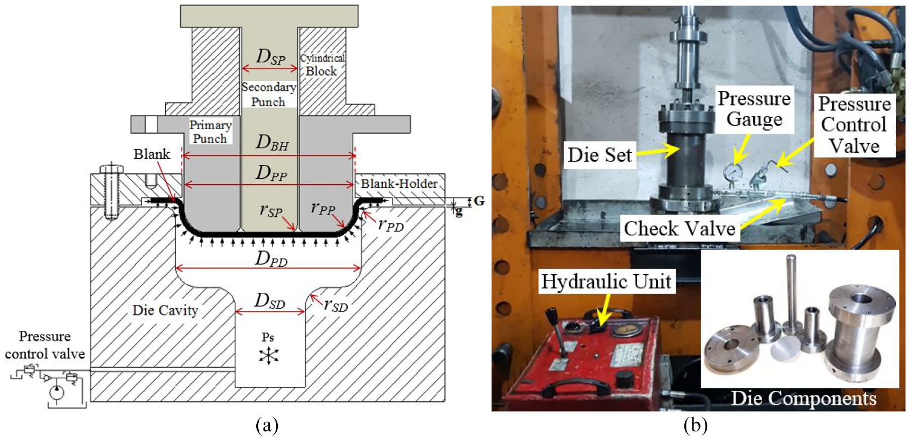
(a) Schematic of TS-HDD process and die parametric dimensions and (b) assembled TS-HDD die installed on the press.
Figure 3 schematically illustrates the forming stages of the TS-HDD process. In stage one, the pre-formed cup is produced by moving the primary and secondary punches in the vertical direction simultaneously, and the oil leakage from the grounded blank holder/die interface causes the pressure around the blank outer edge. In stage two, by removing the cylindrical block and fixing the primary punch on the blank holder, the final cup is formed by moving down the secondary punch. Also, there is low oil leakage from the blank holder/die interface, which creates pressure on the wall and edge of the pre-formed cup. In each stage, the pressure in the die cavity is increased to the maximum value adjusted by the pressure control valve. The blank holder does not apply any force on the sheet independently. In the second stage, the primary punch plays the blank holder role for the pre-formed cup, which is constrained with the main blank holder and also exerts no force on the pre-formed cup. It should be noted that the forming stages are performed consecutively. So, the pre-formed cup is not removed between the first and second stages and no additional operations such as annealing are performed. This is an essential feature of the TS-HDD process in this study.
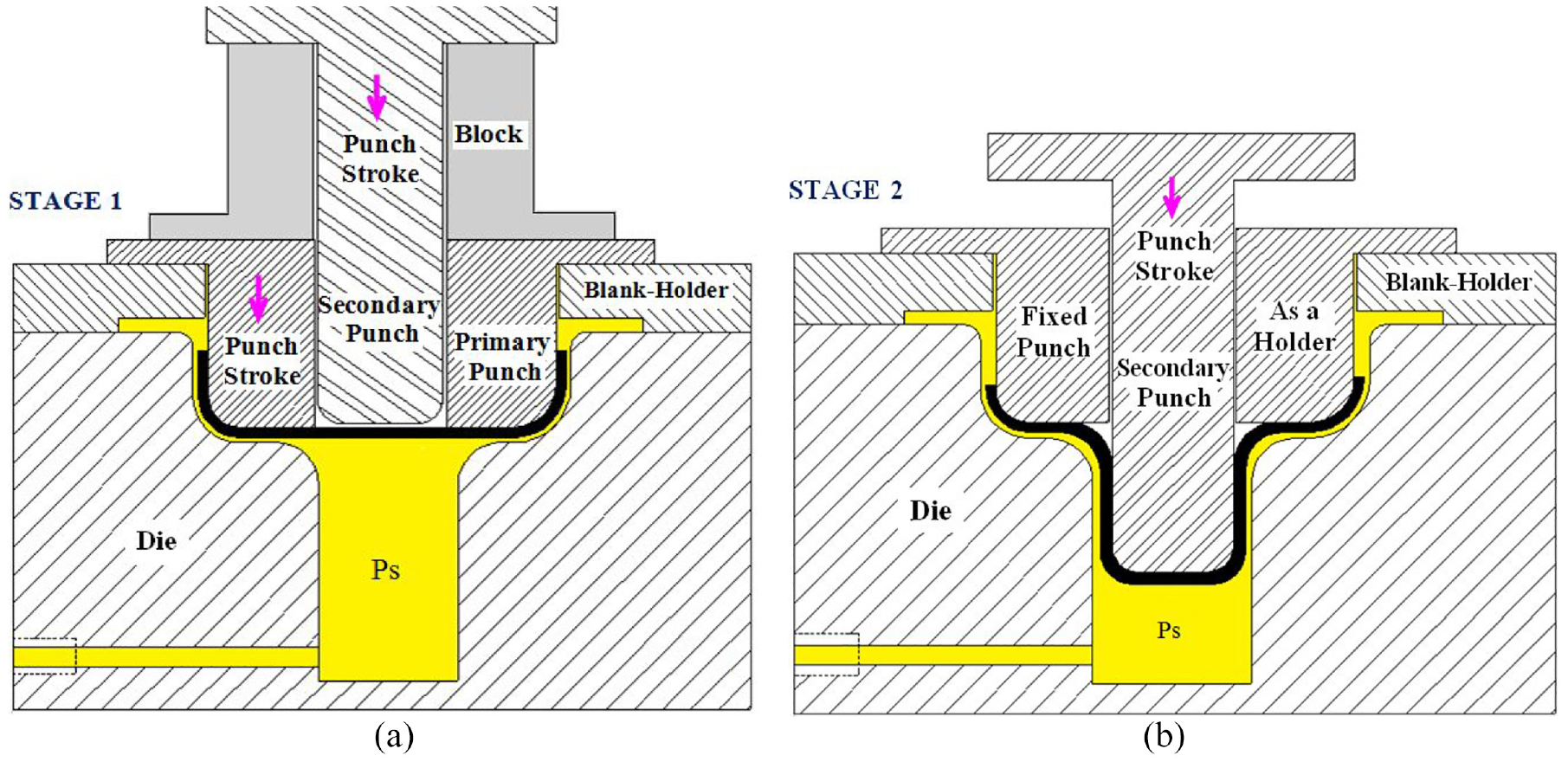
Schematic of: (a) stage one; forming of the pre-formed cup and (b) stage two; forming of the final cup.
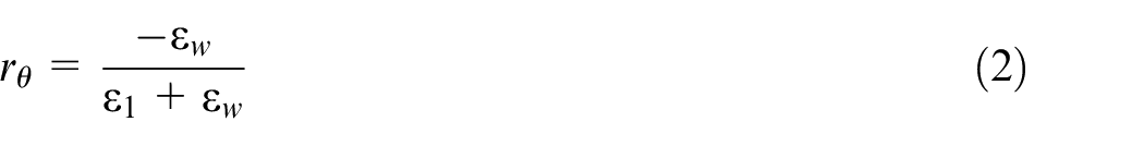
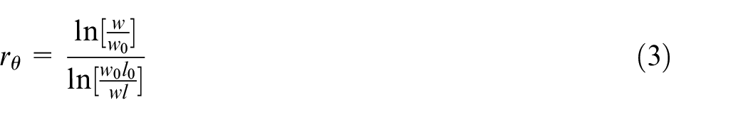
To evaluate the anisotropy behavior at a given angle θ to the rolling direction, the plastic strain ratio (r-value) is calculated using the following equations, 18
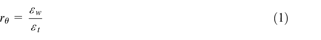
where
where
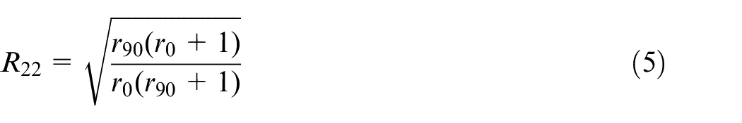
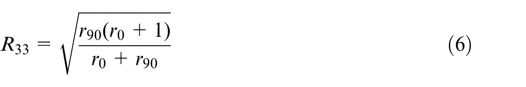
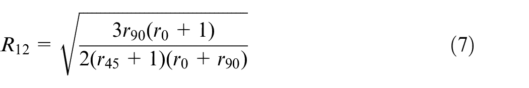
On the other hand, to apply sheet anisotropy in finite element simulation, the yield stress ratios (R values) must be introduced as 19 :
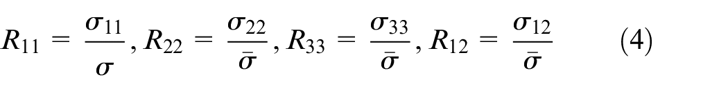
where
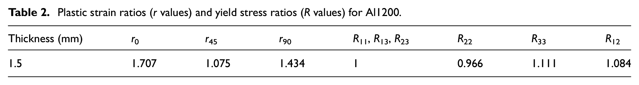
Subsequently, plastic stress ratios can be obtained by equations (5)–(7) with assuming
Plastic strain ratios (r values) and yield stress ratios (R values) for Al1200.
The explicit finite element analysis was used to simulate the process by ABAQUS 6.12. The Hill yield criterion was used to assign anisotropic yielding.
19
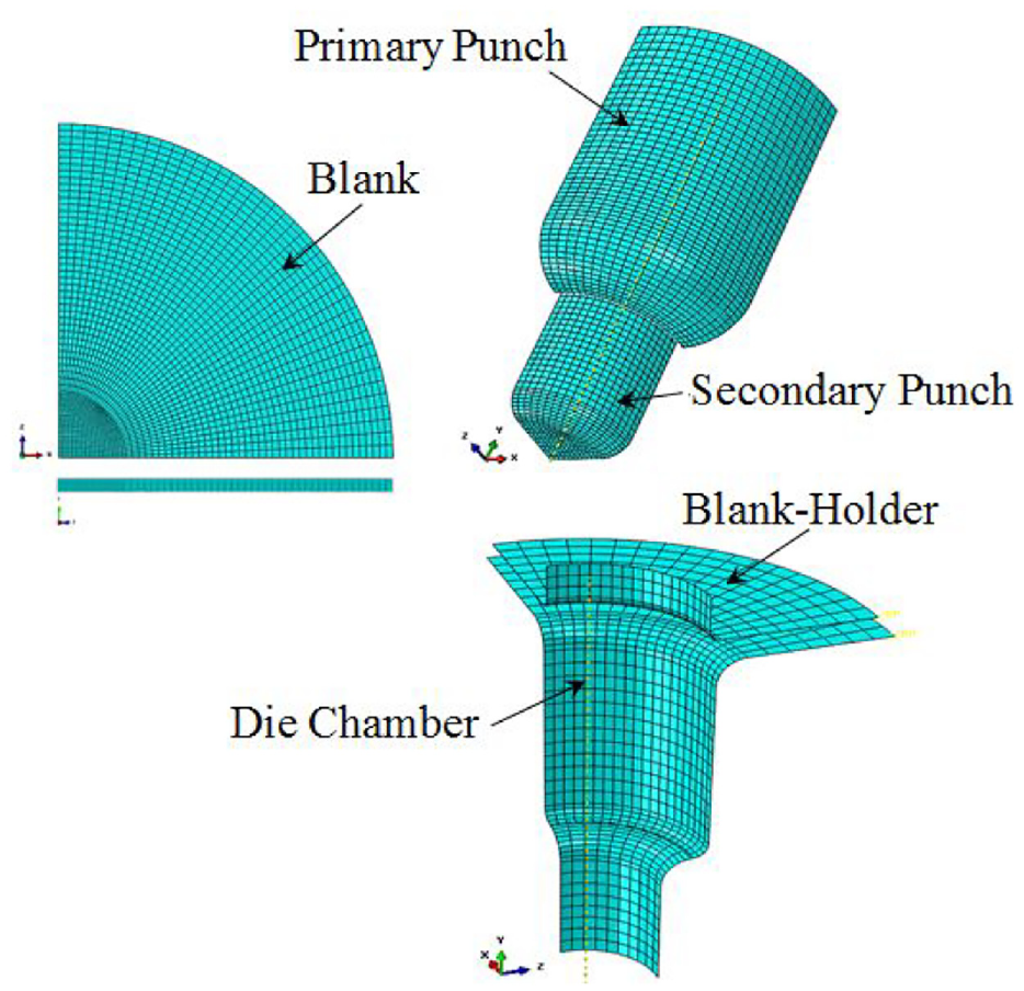
Three-dimensional models were used for the tooling and the blank. Figure 4 shows the FE model of the die for the TS-HDD process. Only one-quarter of the 3D model was used because of structural symmetry and reducing the computation time. C3D8R 8-noded solid linear brick element was used for meshing the blank. Four elements along the thickness were meshed based on the convergence of the maximum punch force. For meshing the die rigid model, a four-node shell element R3D4 was applied. The pressure chamber and the blank holder were entirely fixed while the punches were defined to move in the vertical direction. Fluid pressure constraints were exerted under the blank surface and also on the outer edge of the blank. According to Figure 2(a), the gap between the pressure chamber and the blank holder (G) was exerted and fixed. The velocity of both punches was 20 mm/s. The multiplication factor of 100 was applied in the simulation.
20
At stage two, the primary punch was fixed as a blank holder of the pre-formed cup and the secondary punch moved down with the constant velocity. The whole process was performed in four steps, that is, two steps in each stage; Step one, applying the pre-bulging pressure, and step two, loading the fluid pressure in the pressure chamber. Coulomb friction model was used to define the contact frictions. Coefficients of frictions of 0.14 and 0.04 were used at the punch-blank and other interfaces, respectively.6–8 The Hollomon’s power law equation of
Finite element model of the die set.
The maximum thinning was considered as a fracture criterion which was calculated by equation (8).
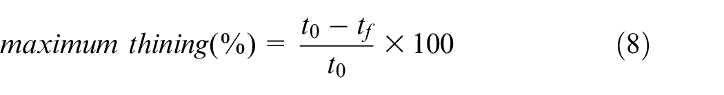
Where
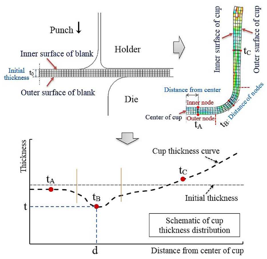
The thickness of the formed cup in the finite element simulations is calculated by measuring the distance between the nodes on the inner surface and the nodes on the outer surface of the blank. Figure 5 schematically shows the method of measuring the thickness of a formed cup by finite element simulation and the corresponding thickness distribution. In this study, the maximum thinning percentage of 41% was obtained, which means rupture occurs if the thickness of the aluminum part in simulations becomes <0.885 ≃ 0.89 mm, and the forming process fails. This value was in close agreement with those measured experimentally.
Schematic of measuring cup thickness in the finite element model.
Results and discussions
Punch diameter ratio (PDR)
In TS-HDD, the diameter of the preformed cup is determined by the diameter of the primary punch, and its height is determined by the limit drawing ratio of the first stage and the diameter of the primary punch. Meanwhile, it is necessary to determine the desired ratio between the diameter of the primary and secondary punches to get the higher total drawing ratio. So, to investigate a criterion for evaluating the degree of formability, the ratio of the primary punch diameter (
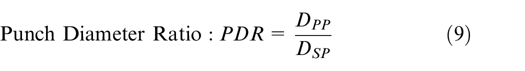
The PDR is approximately equal to the drawing ratio of the second stage. The limiting drawing ratio of stage one (
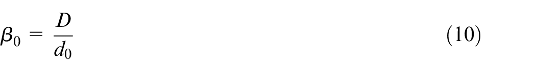
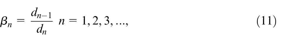
where D is the initial blank diameter,
In this study, the diameter of the secondary punch is constantly equal to 35 mm, so it is necessary to determine the desired primary punch diameter to obtain the desired PDR. A higher amount of PDR makes it difficult to form the final cup and may lead to rupture. On the other hand, lowering the amount of PDR may cause severe thinning or tearing of the pre-forming cup. Therefore, determining the desired PDR can lead to the production of a sound part with a high drawing ratio.
Based on previous studies on the conventional drawing process, the “diameter reduction percentage” according to equations (12)–(14) and “height-to-diameter ratio” according to equations (15)–(17) are used for determining and comparing the formability at each stage:

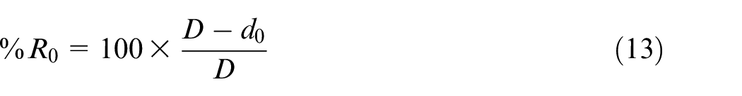
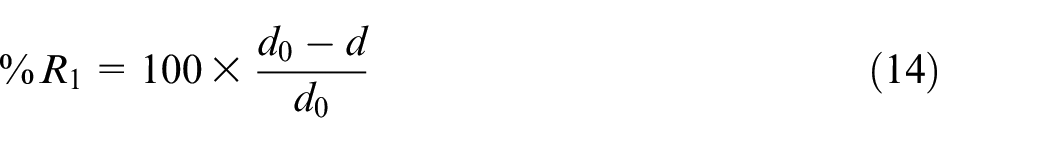
where
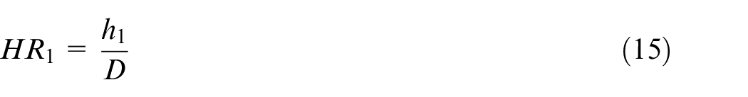
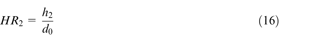
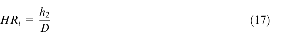
where
Because the maximum possible drawing ratio of the pre-formed cup in the first stage may not result in the best thickness distribution of the final cup and it may even increase the risk of rupture in the second stage, FE simulations were performed for different initial blank diameters of 85, 90, and 95 mm and different primary punch diameters with a constant tip radius of 7 mm to determine the desired drawing ratio. Then, the minimum thicknesses at the critical region of final cups (zone B) were compared as shown in Figure 6(a). The constant maximum pressure of 10 MPa for both stages was applied. As shown in Figure 6(a), the lowest percentage of thickness variation ratio (TVR%) for three different total drawing ratios shows the same results as occurred with the primary punch diameter of 54 mm.
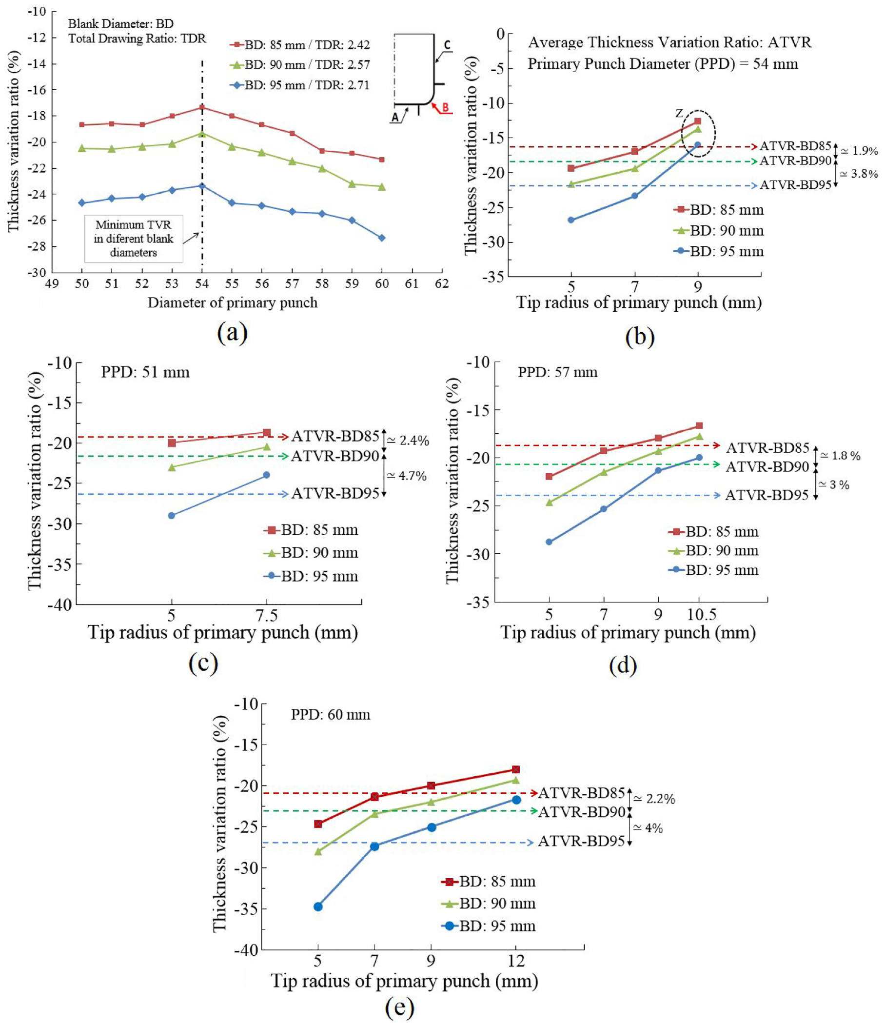
Thickness variation ratio of critical area B: (a) versus different primary punch diameter, and versus different tip radius in primary punch diameter of, (b) 54 mm, (c) 51 mm, (d) 57 mm, and (e) 60 mm.
In the following, to evaluate the effect of the primary punch radius and determine the desired value, experiments were performed by several optional radii for different primary punches diameters and the results were compared (Figure 6(b)–(e)). According to the two-stage die design, for a certain diameter of the primary punch, the maximum size of the punch radius is about the maximum radial distance between the primary and secondary punches’ radii. Therefore, due to the constant diameter of the secondary punch, the maximum applicable radius for the primary punch will also increase with increasing the diameter of the primary punch.
As shown in Figure 6(b) to (e), the thickness variation ratios of the critical region corresponding to the final cup are reduced with an increasing radius of the primary punch tip. Also, it can be seen for all cases that the effect of the tip radius on critical thickness will increase with increasing the diameter of the initial blank, as shown by ATVR%. Also, as shown in zone Z in Figure 6(b), in addition to reducing the amount of thickness variation ratio for the maximum radius (9 mm), the differences between the TVR% of various blanks have been reduced too. This can be seen in almost all other cases too (Figure 6(c)–(e)). Comparing the results shown in Figure 6, it can be seen that despite the increase in maximum tip radius in punches 57 and 60 mm and subsequently decrease in TVR%, the minimum TVR% is related to the radius 9 mm of the primary punch with the diameter of 54 mm. So, according to the results and what was discussed, the primary punch diameter of 54 mm and the radius of 9 mm were considered as the desired values. Due to the constant diameter of the secondary punch (35 mm) and based on equation (9), the desired PDR value was obtained 1.54. So, based on equation (13), the desired
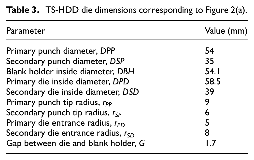
Table 3 shows the TS-HDD die dimensions shown in Figure 2(a). Dimensions of the die and the primary punch were considered based on the results discussed above.
TS-HDD die dimensions corresponding to Figure 2(a).
Forming pressure paths
In the hydroforming process, the pressure loading path affects the part thickness distribution as an important parameter. Since the hydrodynamic process is performed in two consecutive stages, the desired pressure path for each stage should be investigated separately. The basis of the pressure path in this research which applied for each stage was according to paths
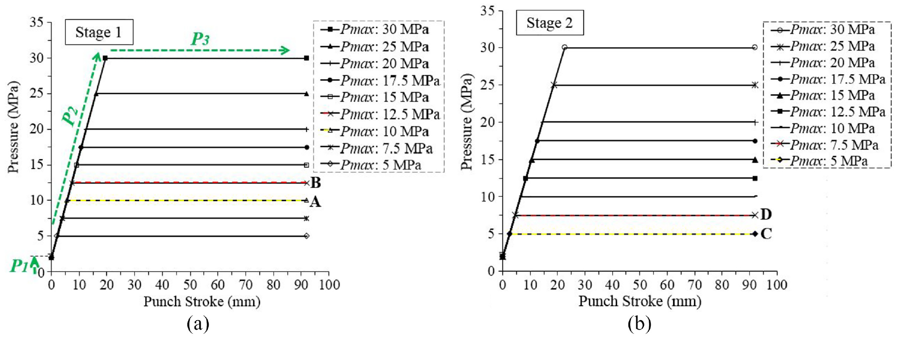
Pressure paths corresponding to different
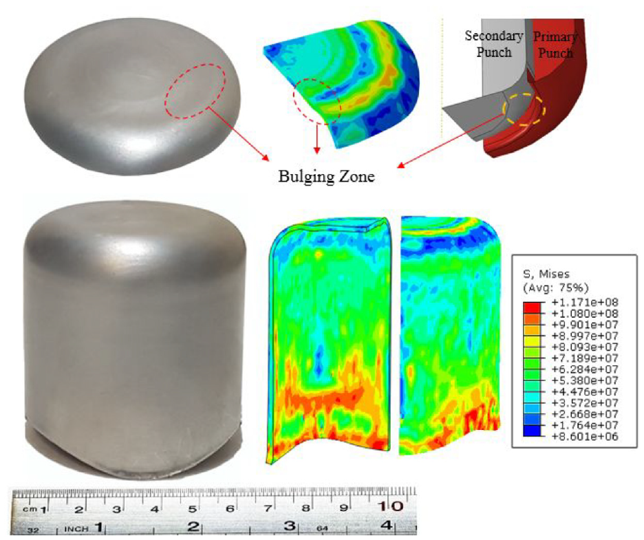
To determine the best pressure path, the variation curves of the thickness decrease in area B of the cylindrical cup were compared at different maximum pressure. Figure 8 shows the thickness decrease curves in area B of the pre-formed and the final cups related to different pressure paths in simulation and experimental tests. It can be seen in Figure 8(a), as the final pressure increases, the decrease in thickness also increases with an almost constant gradient. Also, at the final pressure of near 5 MPa and less, bursting occurred on the radius of the deformed cup. Figure 9(a) illustrates the deformed part in which bursting occurred because of the low level of pressure in the forming stage one. For the maximum pressure between 5 and 10 MPa, the separation defect occurred at the contact area of the pre-formed cup wall with the primary punch. At pressures higher than 10 MPa, the thickness reduction increased with slight fluctuation. Therefore, although higher maximum pressure eliminates the separation defect, it was caused an increase in the thickness reduction and also the punch force. Therefore, the lowest final pressure that resulted in a non-defective part was considered as the desired pressure in stage one.
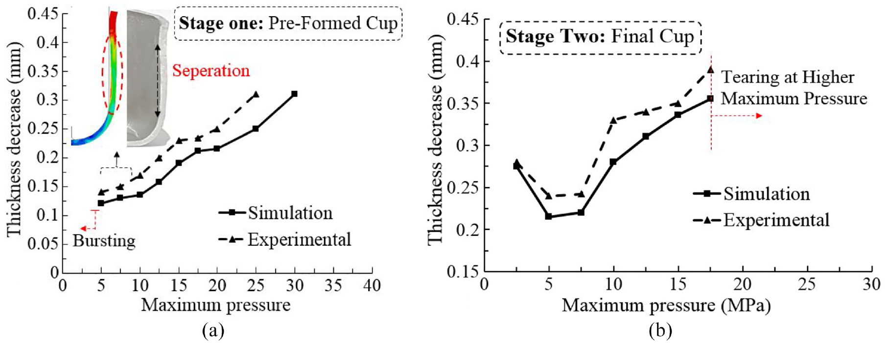
Thickness decrease curve for area B at different maximum pressures: (a) the pre-formed cup and (b) the final cup.
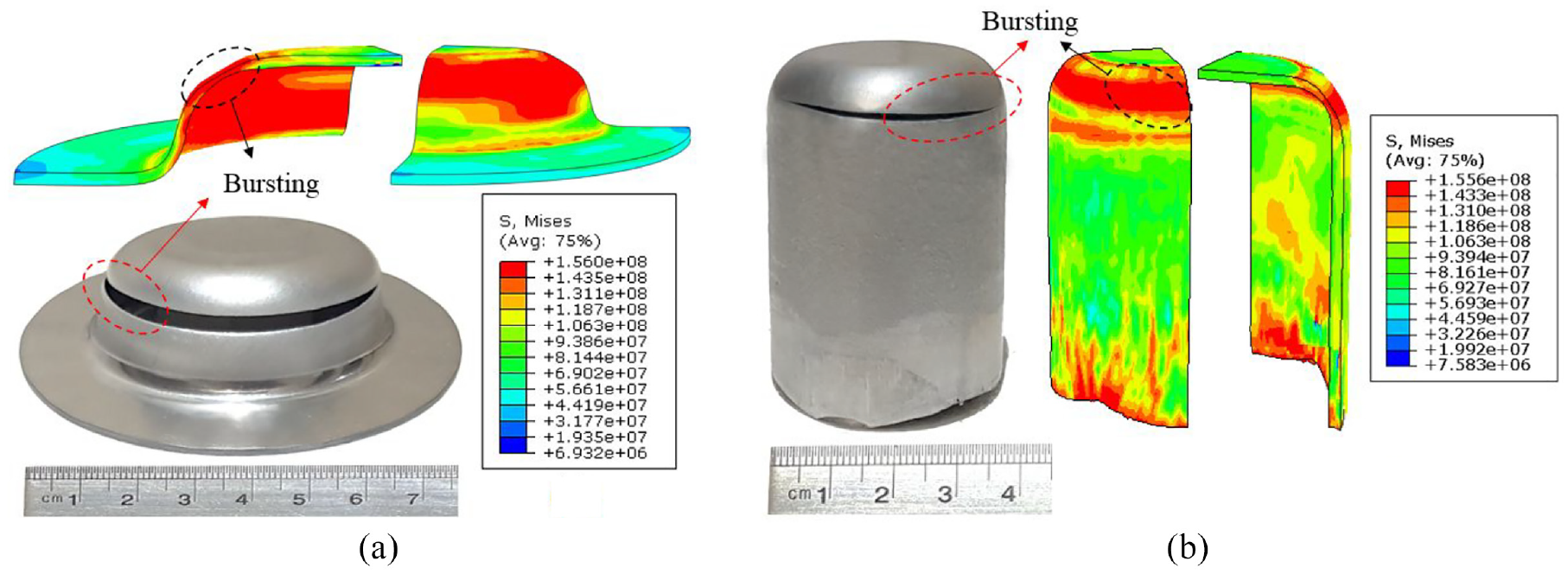
Defective workpieces: (a) the pre-forming stage,
Also, as shown in Figure 8(b), the results for the final cup show that at final pressures lower than 7.5 MPa the thickness decrease was reduced. At maximum pressures higher than 7.5 MPa, the thickness decrease was increased again with a steep gradient. And finally, for the pressures more than 17.5 MPa, tearing occurred in the critical region. Figure 9 indicates the defective part in which the higher level of pressure has caused the bursting of the workpiece at the end of forming stage two.
So, according to the results, considering the pressure paths associated with the least thinning, pressure paths with the maximum value of 10 and 5 MPa were considered as the desired pressure paths of the primary and secondary forming stage, respectively. Figure 10 shows the thickness distribution curve and final aluminum cup formed with a high drawing ratio by these pressure paths (paths A and C in Figure 7). The critical zone is B where the highest reduction in thickness occurred. Furthermore, it is worth mentioning that the maximum prediction error of thickness distribution is 5%, which is due to the error accumulation and the material work hardening at the primary stage.
Final cylindrical cup and thickness distribution curve corresponding to the paths with
Maximum drawing ratio (MDR)
To determine the maximum possible total drawing ratio (
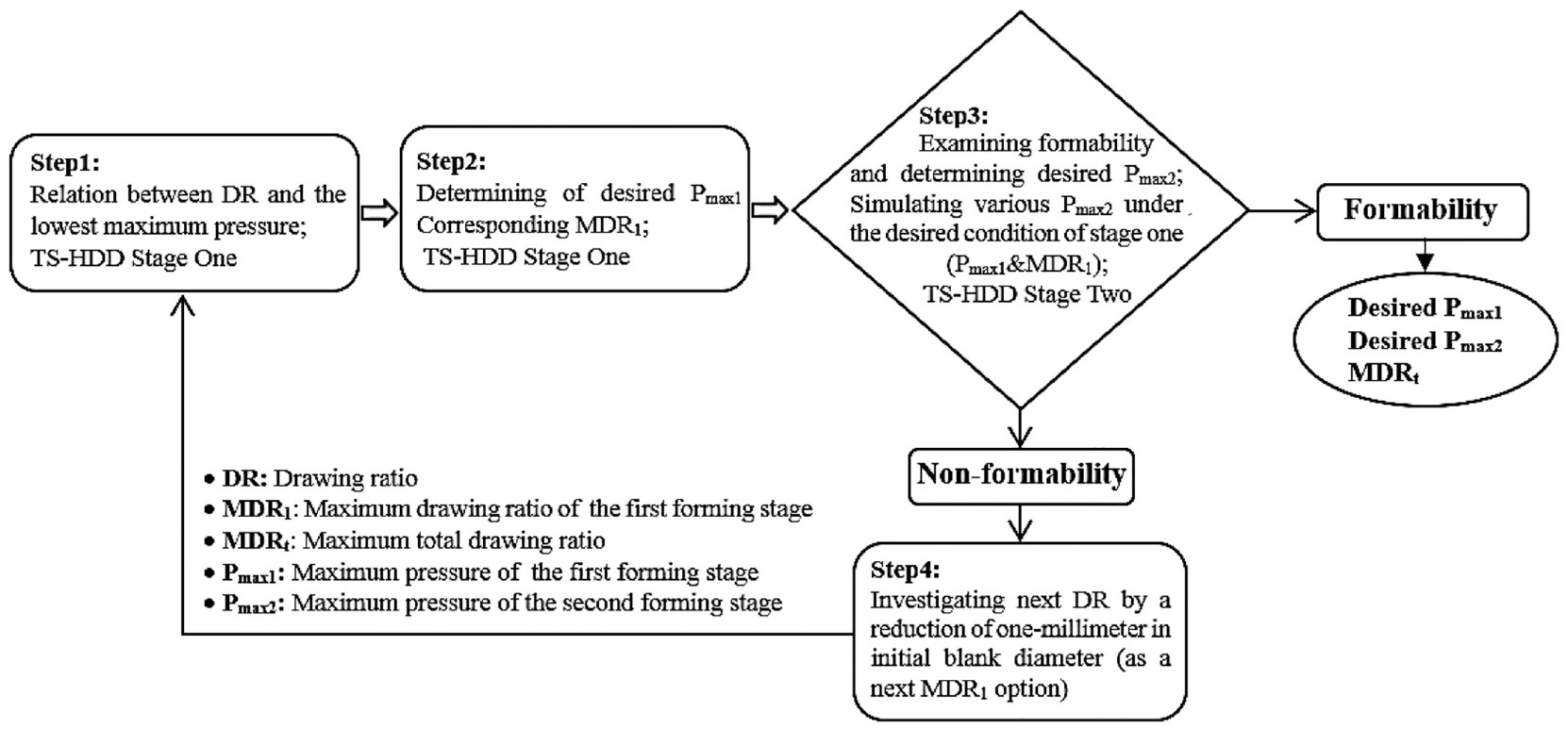
Framework to determine maximum drawing ratio in TS-HDD process.
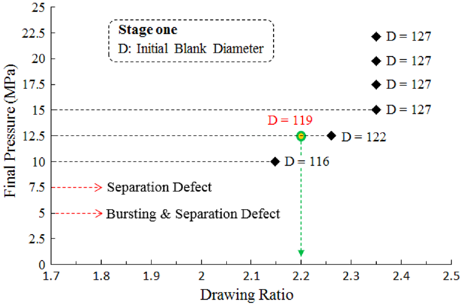
The drawing ratio corresponding to maximum pressure in stage one of TS-HDD.
According to the results, the
Figure 13 shows the simulation and experimental pre-formed cup corresponding to the
The pre-formed cup corresponds to the path with a final pressure of 12.5 MPa.
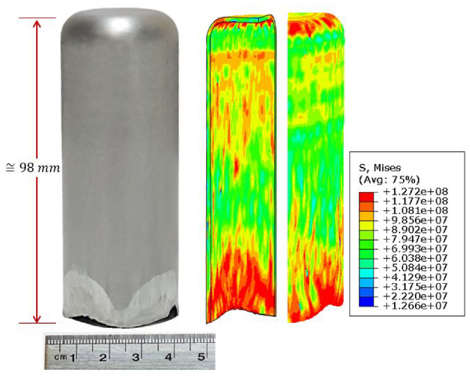
The final cup corresponds to the path with a final pressure of 7.5 MPa.
The desired working and geometrical conditions of cups in TS-HDD.
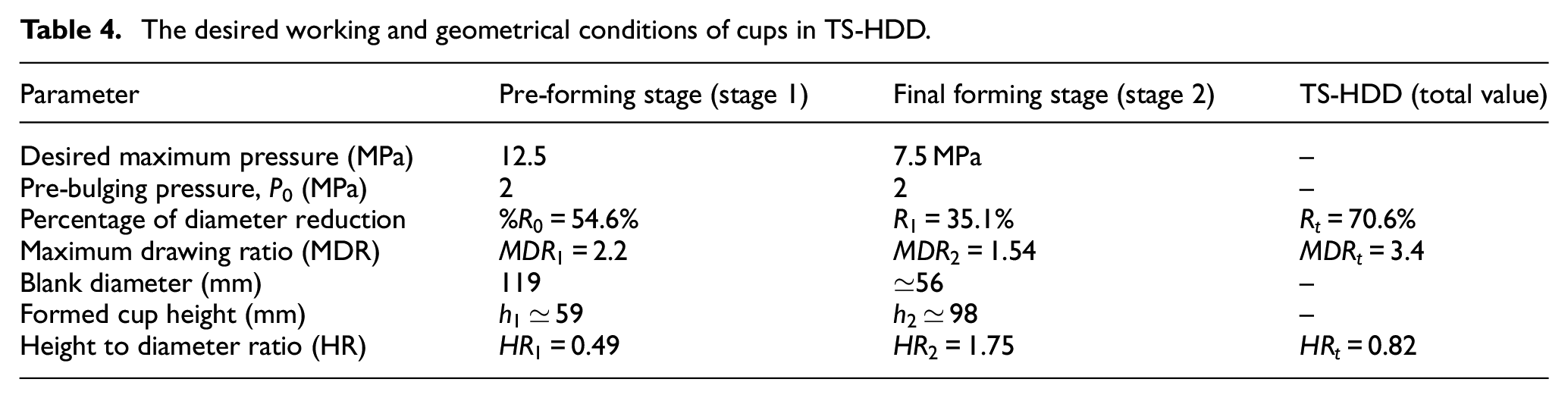
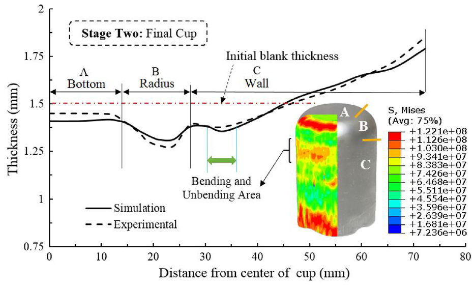
Figure 15 indicates the thickness distribution of the final formed cup with the maximum drawing ratio. The precision of the numerical model along the A-B-C direction was validated by the experiment. The highest decrease in thickness occurred in the radius of the final cup (critical zone B). Also, there is a slight local thinning in the cup wall area which occurred due to bending and unbending in the tip radius area of the pre-formed cup. The maximum prediction error of thickness distribution is 5%, which is attributed again to the error accumulation and also the effect of material work hardening during the process.
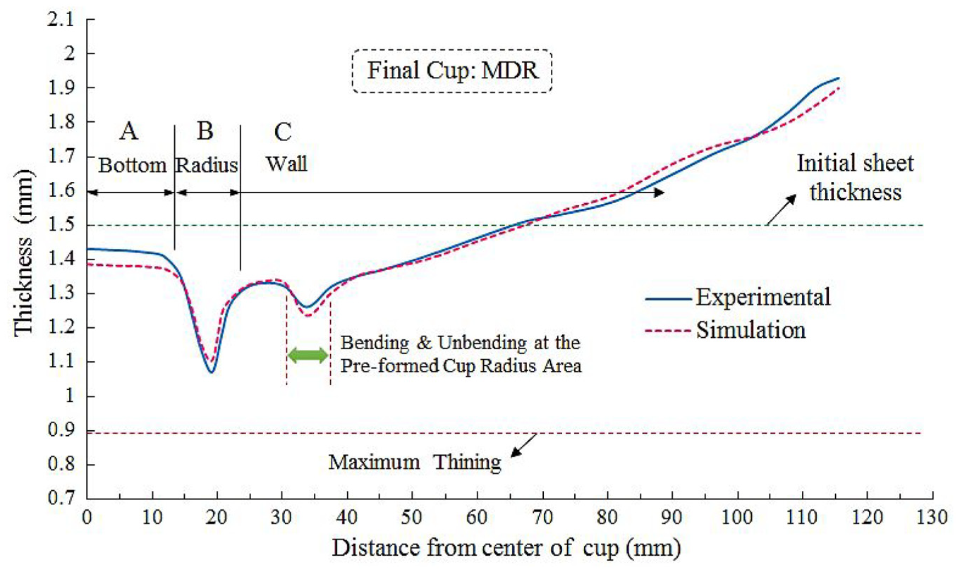
Thickness distribution curve of the final cup with the maximum drawing ratio.
As it was discussed, a cylindrical Al1200 cup was formed with a high drawing ratio of 3.4 and
Conclusion
In this research, a two-stage hydrodynamic deep drawing (TS-HDD) was proposed as a new design of the HDD process. To study the process efficiency, the effects of process parameters on thinning and rupture of aluminum Al1200 cylindrical cups were discussed by experiments and FE simulations.
The punch diameter ratio (PDR) and the primary punch tip radius were investigated by FE simulations. The PDR of 1.54 and the punch tip radius of 9 mm were obtained as the desired values which led to the smallest thinning percentage at the final cup critical area.
Then, the effects of pressure paths on cups thickness were examined for a specified initial blank diameter. It was concluded that rupture, separation defects, or critical thinning occurred in the lower final pressure. The separation defect was eliminated by increasing the maximum pressure, but higher maximum pressure led to higher thinning and tearing in the critical area. Therefore, in both forming stages, the pressure paths with the lowest maximum value that produced a sound part were considered as the desired pressure paths (
Finally, the maximum possible total drawing ratio (
Footnotes
Declaration of conflicting interests
The author(s) declared no potential conflicts of interest with respect to the research, authorship, and/or publication of this article.
Funding
The author(s) received no financial support for the research, authorship, and/or publication of this article.