
Abstract
In this article, a deep-drawing process using a double-action hydraulic press is examined for its ability to machine the shaping deformation of a fuel-filter cup made from SPCC steel. Many researchers have studied the geometric, physical, and technological parameters of the deep-drawing process. However, most of those studies ignored the optimization parameters of the two shaping deformation states to ensure uniformity of thickness and the disappearance of wrinkling and tearing during machining. In this study, geometric and technological parameters (e.g. blank-holder force, die-shoulder radius, and radial clearance between punch and die) are optimized in both states. The deep-drawing process for a fuel-filter cup is simulated using ABAQUS software, and optimal parameters are determined by applying the Taguchi orthogonal array computation and combining it with an analysis of variance method. The numerical results are then verified with corresponding experiments. The obtained numerical and experimental results show that the die-shoulder radius is one of the most influential parameters affecting the shaping of the cup during the deep-drawing process. Moreover, the influences of technological parameters on the formability of sheet metal are finally analyzed and selected for designing and improving deep-drawing molds.
Keywords
Introduction
Fuel-filter cups on cars and trucks are used to remove impurities from oil before returning it to the engine for lubrication and cooling. These cups are formed using a double-action hydraulic press with a deep-drawing process. Sometimes during this process, cups suffer wrinkling, tearing, and uneven thicknesses. To avoid these defects, fuel-filter cups are machined through two deformation states. Optimal parameters for the deep-drawing process are essential for improving cup quality. Padmanabhan et al. 1 sought to optimize sheet-metal forming using the finite element method (FEM) with the Taguchi orthogonal array. The die-shoulder radius, blank-holder force (BHF), and characteristic friction coefficient of a deep-drawn cup made of stainless steel were used to reduce production costs. Raju et al. 2 researched the influence of technological and geometric parameters of the deep-drawing process for cups made of sheet material AA6061. The Taguchi orthogonal array was used to determine the BHF, the shoulder radius of the die, and the nose radius of the punch. Singh et al. 3 discovered the effectiveness of deep-drawing parameters (e.g. shoulder radius of die, nose radius of punch, coefficient of friction, and rate of deep drawing) based on the Gen algorithm with the cylindrical shaping process. Wifi and Mosallam 4 researched the FEM-based assessment of performance for some non-conventional blank-holding techniques. A three-dimensional (3D) explicit-FEM was used to investigate the influence of various BHF on sheet-metal formability limits (viz. wrinkling and tearing). Aleksandrovic and Stefanovic 5 used the BHF to control the friction on the blank holder during the deep-drawing process. Their cup was made of low-carbon steel sheet using three friction regimes (i.e. dry, oil, and polyethylene terephthalate foil). Reddy et al. 6 and Gharib et al. 7 developed optimizing coefficients for the deep-drawing process to determine BHF and minimize the drawing force. It was achieved without defects. Atrian and Fereshteh 8 examined the effects of various deep-drawing process factors for steel and brass workpieces. FEMs were constructed and tested to show the tearing position on a cup. Sheng et al. 9 studied the formation of tearing and wrinkling as two main failures in the deep-drawing process. Simulation and experimental models were built and compared to improve the process.
The proposed model has been successfully applied to two cone-drawing processes. Sherbiny et al. 10 developed a FEM to simulate the deep-drawing processes for 3D sheet metal using ABAQUS/EXPLICIT FEM analysis software with appropriate material properties and boundary conditions. The development model of reverse elasticity prediction and distribution of thickness of the sheet metal were affected by the parameters of the deep-drawing process, including geometric and physical parameters. Nguyen et al.11–15 performed FEM simulations to investigate the influence of technological and geometric parameters on the deformation of various products to improve the formability of materials.
In this study, FEM and experimental models are constructed for the deep-drawing process of a fuel-filter cup. Numerical simulations using the Taguchi orthogonal computation and analysis of variance (ANOVA) methods are used to determine the optimal parameters. Then, the optimal geometric and technological parameters are applied to ensure uniformity of thickness without the tearing and wrinkling phenomena. Numerical and experimental results show that cup defects are significantly reduced with the proposed method.
Geometric model and material of the fuel-filter cup
Geometric model
The fuel-filter cup is usually used in cars to filter out dregs and rust in fuel and create clean fuel for engines. The shape and size of fuel-filter cups are shown in Figure 1. The shaped surface is required to be absent wrinkling, tearing, or scratching. The normal thickness of the fuel-filter cup is 0.6 mm, and the variation of thickness should not exceed 0.1 mm with the deep-drawing process. The 3D model of the cup is used to design a deep-drawing mold using ABAQUS software. In Figure 1,
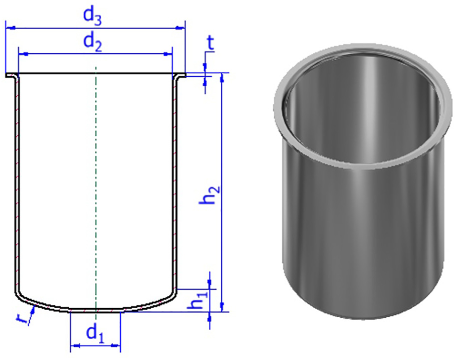
The size and shape for 3D model of fuel-filter cup.
Material
The fuel-filter cup is made from SPCC sheet steel (JIS G3141), having a thickness of 0.6 mm. The mechanical properties of the steel (i.e. directional tensile strength and material response curve) are used in the FEM simulation, as shown in Table 1. The flow-stress curve of SPCC sheet steel is defined with equation (1)
where K is the plasticity coefficient,
Properties of the SPCC sheet steel (JIS G3141). 15

Deep-drawing process of the double-action hydraulic press
FEM model
In this study, the deep-drawing process of shaping the fuel-filter cup is simulated with ABAQUS software. 16 The 3D FEM model for the deep-drawing process is shown in Figure 2, wherein the punch is fixed, and a blank holder and die are moved in the vertical direction to achieve the size of the shaped cup via two deformation states. Rigid models are used to analyze the punch, blank holder, and die, and their displacements are represented with reference points. The blank is modeled using deformable elements and a shell model of S4R-reduced integration.

The 3D model of FEM in ABAQUS software.
To express the anisotropic behavior of the material, elastic and plastic deformations of SPCC sheet steel were simulated based on the Hill’48 productivity criteria. 17 The Hill’48 classic-yield surface function is the most prominent and frequently used yield function to account for the plastic anisotropy of steel materials, mainly because of its simple handling in manual and numerical calculations. It is a simple extension of the isotropic von Mises function, which can be expressed in terms of rectangular Cartesian stress components, as used in equation (2)
where x, y, and z are the rolling direction (RD), transverse direction, and normal direction, respectively. F, G, H, and N are the current state parameters of anisotropy obtained by different material tests. They are defined by equation (3)

where
Parameter determination for deep-drawing process
The deep-drawing mold-design parameters are classified into two categories. The first category refers to the geometrical parameters used to design the mold. The second refers to the physical and technological parameters used during the deep-drawing process.
Design geometric-parameter determination of the fuel-filter cup molds
To design fuel-filter cup molds, geometrical parameters should be recognized, as shown in Figure 3, where

General geometric parameters of the cup molds.
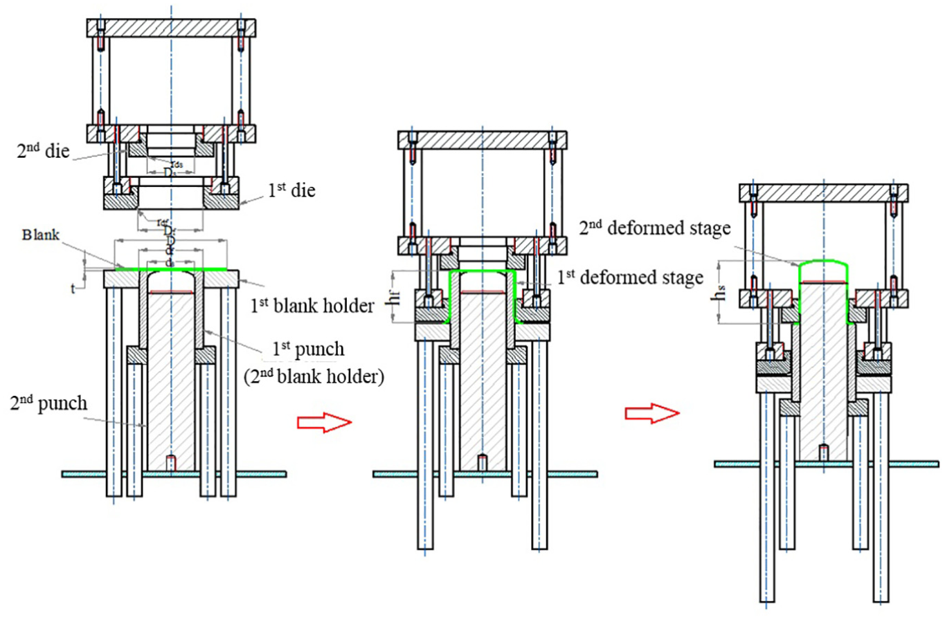
Deformation state model on the double-action hydraulic press machine.
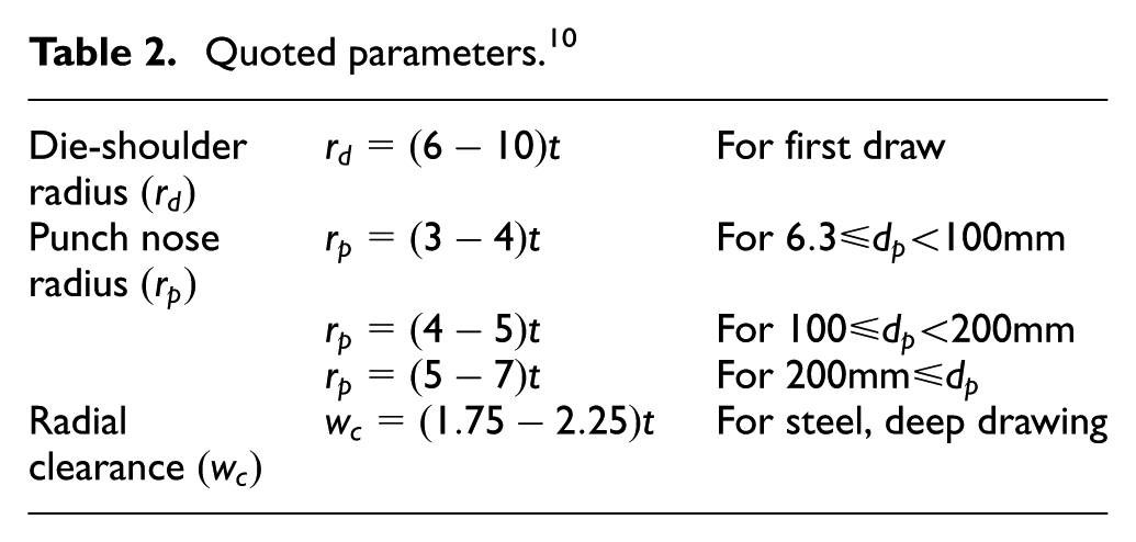
Quoted parameters. 10
Before starting the deep-drawing process, the size and shape of the workpiece must be identified for mold design. From the requirements of cup shape and size, as shown in Figure 1, the diameter of the blank is determined. To calculate the blank diameter, the entire symmetrical part of the cup must be divided into different individual symmetry axis components. Then, its surface areas are calculated. The diameter of the original blank can be determined using equations (5) and (6) 18


where


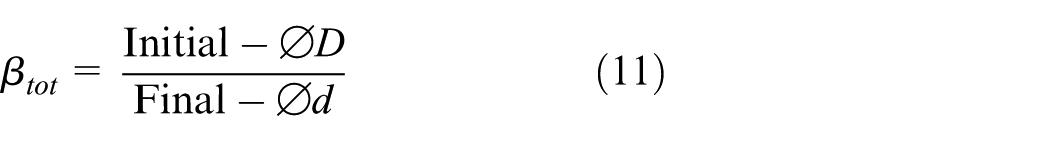
The total deep-drawing factor is calculated using the ratio between the diameters of the original blank and the final diameter of the deep-drawing process, as shown as equation (11)
With several deep-drawing steps, the total draw factor becomes a product of the individual draw ratios of equation (12)

The maximum height can be achieved from the size of the original blank using an approximate calculation, where the thickness of the drawing cup equals the thickness of the blank, and the radius of curvature of the punch can be ignored. The height of the filter cup for the first deformation state can be defined with equation (13) 19

where

Obviously,
Physical and technological parameter determination
To determine the physical and technological parameters used in the deep-drawing process, Figure 5 can be used, where

Friction areas when deep drawing a cup.
With deep drawing, tearing defects are caused by uncontrolled deep forces (equation (15)) that cannot be transmitted to the bottom of the cup 20

where


Work domain of blank-holder force in deep drawing.
Numerical simulation and experimental results
Numerical simulation
In this study, a FEM simulation was conducted and verified using a Hyundai design fuel-filter cup and the general parameters shown in Figure 1.
Based on calculated technological, geometric, and physical parameters, the preliminary data sheet of the deep-drawing mold used to determine the region of the BHF by means of FEM simulation and experiment is expressed in Table 3.
Geometric, technological, and physical parameters of the deep-drawing mold.

By using the FEM to simulate as the setting parameters, Figures 7 and 8 depict the deformed shapes of wrinkling and tearing phenomena when changing the BHF
Limited domain of blank-holder force (FBH) between wrinkling and tearing occurrence in the FE simulation in the first deformed state: (a) FBH = 9 tons (wrinkling) and (b) FBH = 13 tons (tearing).
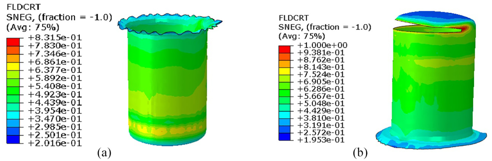
Limited domain of blank-holder force
Experimental results
The deep-drawing process of the fuel-filter cup was performed on the double-action hydraulic press at the maximum load capacity of 50 tons. Market oils were used as lubricant. 19 The experimental setup is shown in Figure 9. To confirm the accuracy of FEM results, corresponding experiments were conducted, as shown in Figure 10. The results showed good agreement between numerical simulation and experimental results.

The double-action hydraulic press and deep-drawing mold.

Typical wrinkling (a) and tearing (b) occurrence on the surface of the fuel-filter cup.
Parameter optimization
To improve the formability of the product, the deep-drawing process of the first deformation stage was performed as shown in Figure 11(a). During this stage, wrinkling at the top of the cup and uneven thicknesses occurred. Therefore, the measurement of 10 points on the wall angle of the cup was adopted, as shown in Table 4. Figure 11(b) shows experiments and corresponding FEM simulation results along the cross-section. The average thickness distribution from the FEM simulation was near the average thickness obtained from the corresponding experimental result. The difference between the average measured results on the FEM and experiment was lower than 1.6%. From the comparison data of the FEM and the corresponding experimental results, an optimal process is needed to obtain the uneven thickness values of the cup wall after deep drawing in the first deformation stage to prevent tearing during the second stage.

The location of the filter cup thickness at the first stage with original design by (a) experiment and (b) simulation.
Comparison between experimental results and FEM predictions for wall thickness.

FEM: finite element method.
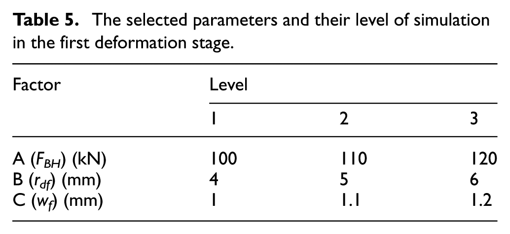
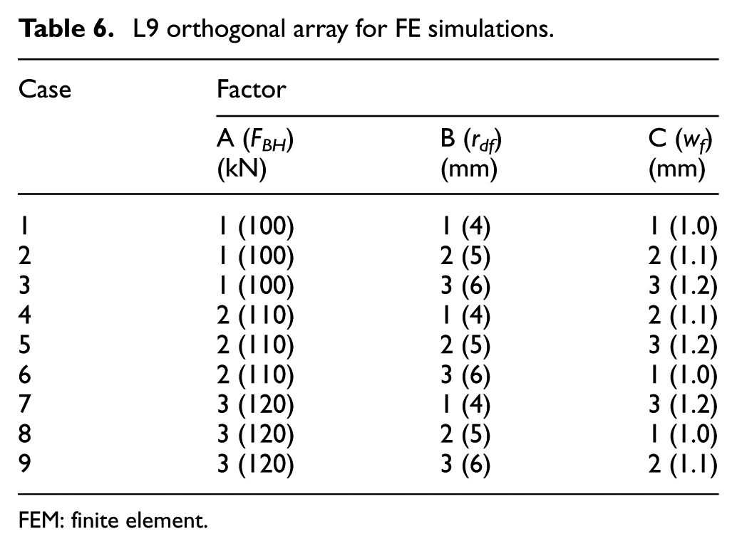
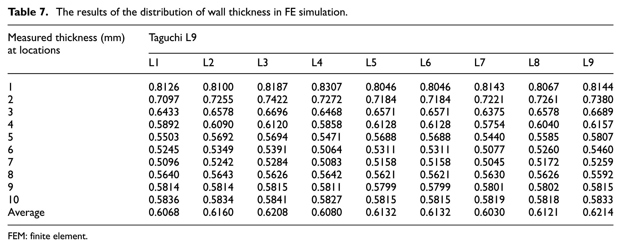
There are various parameters effected during wrinkling and tearing, such as BHF, radial clearance between die and punch, die/punch shoulder radius, and so on. If those conditions change, the stress and strain of the cup will also change, leading to changing thickness of the sheet and the ductile fracture forming-limit diagram failure criterion (FLDCRT) in the FEM simulation. Thus, in the current study, the influence of the BHF (FBH), die-shoulder radius (rd), and radial clearance between die and punch (wc) on the formability of product was evaluated. The BHF was determined using the limitations between wrinkling and tearing. Table 5 lists the levels of the selected parameters. Using the Taguchi method 22 and an orthogonal array, L9 was used for experimental design planning. Using the Taguchi orthogonal algorithm reduced the number of experimental designs from 27 to 9 cases, as shown in Table 6. Table 7 and Figure 12 present the measured thickness results of 10 points along the wall angle of the product via FEM simulation, according to the Taguchi orthogonal algorithm (i.e. L9).
The selected parameters and their level of simulation in the first deformation stage.
L9 orthogonal array for FE simulations.
FEM: finite element.
The results of the distribution of wall thickness in FE simulation.
FEM: finite element.

Thickness distribution of wall angle from FEM simulation.
From the wall-angle thickness measurements of the FEM (Table 7 and Figure 12), the thinness position occurred at point 7, where the cup thickness was 0.5045 mm, 15.92% thinner than the original (case no. 7). Otherwise, case no. 3 of the FEM simulation had the smallest thickness (0.5284 mm), 11.93% thinner. Thus, case L3 (A1B3C3) with BHF (FBH1) = 100 kN, die-shoulder radius (rdf) = 6 mm, and radial clearance between die and punch (wf) = 1.2 mm were chosen for the first deformation stage.
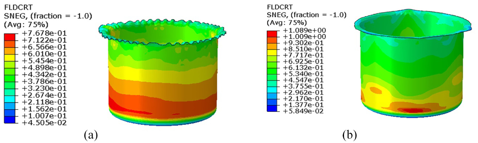
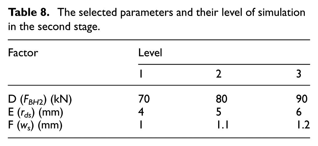
In the fuel-filter cup deep-drawing process, thin variations in the wall-angle and tearing often occurred during the second deformation stage. The Taguchi orthogonal array was carried out via simulation for each case based on the levels of the selected parameters (Table 8). The FEM simulation results are shown in Table 9, indicating the FLDCRT of the final shape. If FLDCRT > 1, a fracture will occur. According to the Taguchi method, the bigger the FLDCRT, the better the formability of the final product. Then, the signal-to-noise ratio is determined with equation (17). As shown in Table 9, The phenomenon of ductile fracturing during simulation occurred for cases 1, 4, 7, and 8, where the FLDCRT value was greater than one unit

The selected parameters and their level of simulation in the second stage.
Simulation results by Taguchi orthogonal array.

FLDCRT: forming-limit diagram failure criterion.
As part of the Taguchi method, 21 ANOVA was used to describe the relationship between the parameters and the observed values of the FLDCRT. Table 10 summarizes the calculated results of equations (18) and (19)

where

and

Results obtained after calculation.

Indicates the optimal level.
The results ANOVA, shown in Table 10, support that the die-shoulder radius, rd, was the most influential for shaping at 52.5%. The influence of BHF (FBH) and the radial clearance between the punch and die were 36.4% and 11.1%, respectively. Thus, the die-shoulder radius was the most important factor of the formability of the final product after FEM simulation.
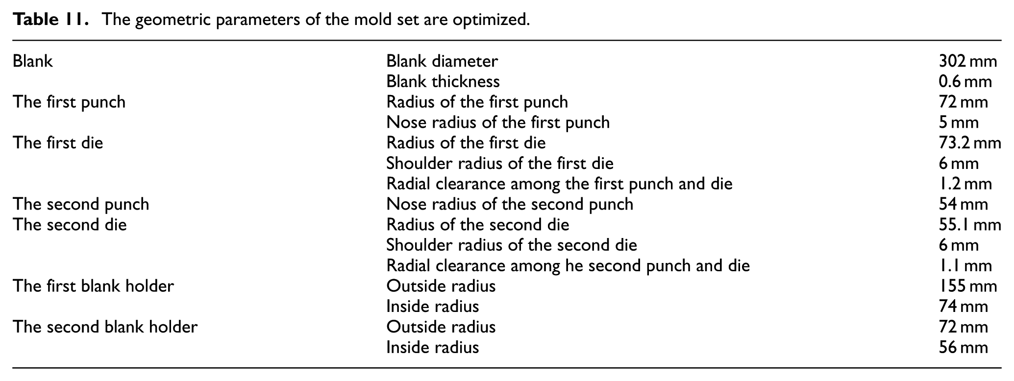
Via the combination of FEM simulations and Taguchi orthogonal arrays, the influence of component parameters on the formability of the final shape was analyzed for the second deformation stage. The selected parameters, D1E3F2 (BHF (F) of 70 kN, die-shoulder radius (rds) of 6 mm, radial clearance between punch and die (ws) of 1.1 mm, respectively) should be used for the deep-drawing process at the second deforming stage. To validate the FEM simulation result, the experiment was set up with a double-action hydraulic press of 500 kN and a punch speed of 1 mm/s. Table 11 and Figure 13 show the dimensions and geometrical parameters of the injection molds, respectively. Optimal result of FEM simulation and corresponding experiment are also presented in Figure 14, showing good agreement.
The geometric parameters of the mold set are optimized.

The composition of the mold after improving by FEM: (a) Blank holder, (b) the first punch, (c) the second punch, and (d) die for first and second stages.

Deformed shape in FE simulation (a) and experiment (b) of the optimal case.
Conclusion
A combination of the FEM and our deep-drawing process was proposed to determine the optimal parameters for manufacturing the molds of fuel-filter cups. The results showed that
The similarity between the results of the uniformity of thickness of the plate in the experiment with the FEM was a very small range, not exceeding 1.6%.
During the first deformation stage, the fuel-filter cup with BHF, FBH1 = 100 kN; die-shoulder radius, rdf = 6 mm; and radial clearance between punch and die, wf = 1.2 mm, ensuring more uniformity and a minimum thickness of the cup.
The second stage gave optimal results of FLDCRT = 0.7563, ensuring no cracks and no tearing with an optimal BHF, FBH2 = 70 kN. The die-shoulder radius, rds = 6 mm, and the radial clearance between punch and die, ws = 1.1 mm, where the die-shoulder radius was the most important parameter affecting the formability of the final shape with a 52.5% contribution.
Our experiment with optimal parameters provides a reliable method of fabricating a final product without wrinkling and tearing, and it guarantees the formability of the deep-drawing cup according to technical requirements.
Footnotes
Handling Editor: Jianbo Yu
Declaration of conflicting interests
The author(s) declared no potential conflicts of interest with respect to the research, authorship, and/or publication of this article.
Funding
The author(s) received no financial support for the research, authorship, and/or publication of this article.