
Abstract
Thermal efficiency development in a square channel heat exchanger attached with sinusoidal wavy surface is presented numerically. The affectation of flow attack angles (α = 30°, 45°, and 60°), flow directions or sinusoidal wavy surface arrangements (V-apex directing downstream named “V-Downstream” and V-apex indicating upstream named “V-Upstream”), and amplitude ratios (blockage ratios = 0.10, 0.15, 0.20, and 0.25) for heat transfer and flow structure are examined for laminar flow regime (Re = 100–1000). The physical model for the present investigation is validated with the correlation data. The current problem is resolved with the finite volume approach (semi-implicit method for pressure-linked equations algorithm). The computational information is illustrated in forms of flow topology and heat transfer mechanism in the square channel heat exchanger. The understanding of flow topology and heat transfer mechanism in the square channel heat exchanger is important knowledge to develop the heat transfer coefficient in the heat exchanger. The present of the sinusoidal wavy surface in the square channel heat exchanger can expand the heat transfer coefficient greater than the plain channel in all examples (Nu/Nu0 > 1). The maximal heat transfer rate is around 5.58 times above the plain square unit with the optimal performance around 1.98.
Introduction
The development for thermal effectiveness in several kinds of heat exchangers and many engineering devices had been performed by many researchers. The thermal performance and heat transfer enhancements in heating/cooling systems can be divided into two ways: passive and active techniques. The active technique is the addition of the energy such as vibration into the system to grow heat transfer coefficient and efficiency. The passive method is the placement of the vortex generator or turbulator such as wing, winglet, baffle, and so on, into the system to create the vortex/swirling flow, which interrupts the thermal boundary layer on the transferred surface. The vortex flow stream and thermal boundary layer disturbance are causes for heat transfer coefficient and efficiency improvements in the heating unit. The passive technique is extremely found in many industries more than the active technique, because the passive technique does not need added power or energy into the system. Therefore, the passive technique system can help to save the operation cost much more than the active technique.
Due to the need of high thermal efficiency of the heating/cooling unit, the experimental research on heat transfer and efficiency augmentations in the heating/cooling systems had been reported. However, almost cases of the experiments cannot explain the flow topology and heat transfer mechanism in the system. The flow topology and heat transfer mechanisms in the heat exchanger unit are important factors to support to design and improve the heat exchanger. Therefore, the numerical researches on flow topology and heat transfer characteristics are performed to describe the topologies in the heat exchanger unit. The numerical investigation is the creation of the computational domain to forecast the flow topology and heat transfer in the system. However, the selection of the numerical investigation must be confident that the design of the computational design has enough reliability to predict the mechanism in the test section.
The experimental and numerical examinations on flow topology and heat transfer behavior in the heating unit that placed with wavy surface and rib are illustrated as follows.
Li et al. 1 experimentally and numerically examined the efficiency in wavy and plain fins with radiantly arranged winglets around tube for fin-and-tube heat exchangers. Zhang et al. 2 presented heat transfer and flow configuration in heating unit with humped wavy surface for the Reynolds number 500–5000. The numerical and experimental researches were selected to solve their problem. The flow structure in the test section was concluded. Lu et al. 3 selected the wavy porous fins in the microchannel heat sink with the main aim to relieve the pressure loss in the heating unit. The effects of wavy amplitude, wavelength, channel width, and channel height on heat transfer, pressure loss, and thermal efficiency were studied. Xiao et al. 4 experimentally examined the heat transfer and performance enhancements in wavy finned flat tubes by water spray cooling for the Reynolds number 210–680. They concluded that the Nusselt number increases around 48%–68%. Chang et al. 5 studied the thermal performance of the longitudinal wavy rib in a wavy two-pass channel with experimental investigation. They indicated that the thermal performance factor is around 1.51–1.62. Harikrishnan and Tiwari 6 informed the influences of skewness on flow configuration and heat transfer behavior in a wavy channel. The effects of wave amplitude, skewness angle, and Reynolds number were numerically studied. The mechanisms on flow topology and heat transfer in the heating section were reported. Aneesh et al. 7 studied the heat transfer coefficient and thermal performance in a wavy channel of printed circuit unit. They found that the thermal performance is around 3.5, 2.5, and 1.5, respectively, for trapezoidal, sinusoidal, and triangular wavy channels. Wang et al. 8 reported the effects of continuous wavy ribs in a square channel of turbine blade on heat transfer and flow structure. The numerical investigation was selected to investigate their work. The influences of rib height, rib round radius, rib angle, and rib thickness on heat transfer rate and flow behavior were studied for the Reynolds number 10,000–40,000. Lin et al. 9 studied the effects of wave length and amplitude of the wavy channel on heat transfer rate and thermal efficiency in a micro-channel heat sink. Khoshvaght-Aliabadi et al. 10 investigated convective heat transfer in a wavy heat sink with rectangular ribs and Al2O3/water nanofluids. They spotted that the heat transfer coefficient and pressure loss increase around 4%–128% and 8%–185%, respectively, when compared with the smooth wavy sink. They also summarized that the thermal efficiency is around 0.93–1.75.
Singh and Ekkad 11 experimentally examined the heat transfer development in a two-pass channel with V-shaped rib and cylindrical dimple for the Reynolds number 19,500–69,000. They reported that the heat transfer rate of the combined generators is higher than the rib or dimple alone. Ruck and Arbeiter 12 numerically studied turbulent flow and heat transfer in cooling channels installed with various shaped ribs. They found that the transverse and V-shaped ribs in the heating channel gives higher heat transfer rate than the smooth channel around 1.6–1.8 and 2.2–2.5, respectively. They also showed that the 60o V-shaped ribs perform the best thermal performance. The flow topology and heat transfer behavior in the heating section were concluded. Ravi and Saini 13 presented heat transfer and friction factor in a solar air heater channel with discrete multi V-shaped and staggered ribs on the absorber plate. The influences of relative staggered rib pitch, relative staggered rib size, and relative roughness width on heat transfer and pressure loss in the channel were studied for the Reynolds number 2000–20,000. They pointed out that the heat transfer in term of Nusselt number increases around 4.52 times above the smooth channel. Wang et al. 14 numerically studied convective heat transfer and friction loss in a rotating rectangular channel with various shapes of discrete ribs. The influences of rib configuration, rib streamwise distance, rib widthwise distance, and inner-half-rib angle on heat transfer and flow pattern were reported. Kumar and Kim 15 considered the efficiency enhancement in a solar air heater unit with multi V-rib and staggered rib with numerical method. They concluded that the discrete multi V-rib with staggered rib shape gives the overall thermal performance around 6% higher than the other shaped ribs. Rao et al. 16 experimentally and numerically examined the heat transfer increment on the surface with micro W-shaped ribs (double V-shaped rib). The Reynolds number in the range around 15,000–30,000 was considered. They claimed that the micro W-rib performs higher heat transfer rate than the smooth plate around 9.6%. Moon et al. 17 showed the thermal performance in the channels inserted with various rib shapes with numerical analysis. The different 16 rib shapes: square, isosceles triangular, fan-shaped, house-shaped, reverse cut-trapezoidal, cut-trapezoidal, reverse boot-shaped, boot-shaped, reverse right-angle triangular, right-angle triangular, reverse pentagonal, pentagonal, reverse right-angle trapezoidal, right-angle trapezoidal, isosceles trapezoidal, and semicircular ribs were compared for the Reynolds number 5000–50,000. They reported that the boot-shaped rib provides the best thermal performance. Du et al. 18 presented convective heat transfer in a heating tube with sinusoidal rib for the Reynolds number 400–1800. The influences of rib height to diameter ratio, rib amplitude to diameter ratio, rib width to diameter ratio, and rib pitch to diameter ratios on heat transfer and flow structure were considered. They concluded that the optimum thermal performance factor is around 1.03–2.75. Khoshvaght-Aliabadi et al. 19 investigated performance improvement in straight and wavy miniature heat sinks with pin fin. They reported that the maximum thermal performance factor is around 2.65. Khoshvaght-Aliabadi and Nozan 20 reported the influence of corrugation shape in the heat sink of electronic devices. Khoshvaght-Aliabadi et al. 21 studied thermal performance of a nanofluid-cooled zigzag miniature heat sink with various pin fin.
As the literature reviews above, the V-shaped baffle/rib has high effectiveness to enhance heat transfer coefficient and efficiency in the heating section. The advantage for the wavy surface is easy to mold. Therefore, the configurations of V-shape and wavy surface are selected for the present investigation. The combination between two types of the vortex generators is called “V-shaped wavy surface.” The V-shaped wavy surface may help to expand the thermo-hydraulic performance and heat transfer coefficient in the square channel heat exchanger (SCHE). The insertion at the center of the SCHE is selected for the installation method. Moreover, the design of the sinusoidal wavy surface (SWS) in the SCHE also considers the manufacture, maintenance, and installation methods in the real system.
The numerical investigation is chosen for the current research. The numerical result helps to describe the structure of flow topology and heat transfer mechanism in the SCHE when equipped with SWS. The computational domain of the SCHE with SWS must be validating. The heat transfer coefficient, friction loss, and thermo-hydraulic performance in the SCHE with SWS are also summarized.
The first part, physical model and boundary condition, will show the configurations of the computation domain for the channel unit placed with SWS. The details of the computational domain and boundary conditions are also illustrated. In the second part, the assumption and initial condition of the current research are explained. The mathematical foundation, which shows the general equations of the present work and important variables, are stated in the third part. The computational method is also declared in this section. The reliability and accuracy of the computational design will report in the numerical validation part. The solutions of the present problem, flow topology, heat transfer configuration and performance assessment, will summarize in the numerical result section. The conclusion is the final section, which states the brief outcome of this research.
Physical model and boundary condition
The SWS is inserted in the middle of the SCHE as depicted in Figure 1. The computational domain (with mesh) for the SCHE inserted with SWS is also reported in the Figure 1. The fine mesh is applied near the square channel walls, where we extremely found the change of the velocity and thermal boundary layers. The hydraulic diameter of the SCHE, Dh, are identical to square channel height, H = 0.05 m. The effects of flow attack angles of the V-apex (α = 30°–60°), flow directions (V-Downstream arrangement (VDA) and V-Upstream arrangement (VUA)), and amplitude ratios (b/H, blockage ratio (BR) = 0.10–0.25) on heat transfer rate and flow configuration are studied numerically in three dimensions for the Reynolds number, Re = 100–1000 (laminar flow region).

SCHE inserted with SWS and computational domain.
The computational models for all examples are developed and set under the following boundary conditions:
The periodic term on flow and heat transfer are set for inlet and outlet of the computational design;
No slip wall condition is applied for all surfaces of the computational domain;
Constant surface temperature around 310 K is applied for the SCHE walls;
The tested fluid (air at 300 K and Pr = 0.707) flows into the SCHE;
The SWS is assumed to be insulator (heat flux around 0 W/m2).
Assumption and initial condition
Laminar region of the air with the Reynolds number around 100–1000 is analyzed for the present investigation. The test fluid is supposed to be incompressible fluid. The change of the thermal properties for the air is ignored. The thermal properties of the airflow are set at the average bulk mean temperature. The flow and heat transfer are steady in three dimensions. The forced convection in the SCHE is regarded, while the natural convective heat transfer and radiation are assumed to be neglect. The body force and viscous dissipation are unconsidered.
Mathematical foundation and computational method
The numerical method for the present investigation is referred from Promvonge et al. 22 The SCHE installed with the SWS is dominated under three important equations: the continuity, Navier–Stokes, and the energy equations.
Continuity equation

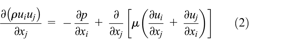
Momentum equation
Energy equation

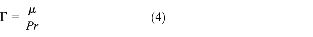
where Γ is the thermal diffusivity and is given by
The energy is discretized by the quadratic upstream interpolation for convective kinematics (QUICK) scheme, while the governing equations are discretized by power law scheme. The present examination is resolved by finite volume technique with semi-implicit method for pressure-linked equations (SIMPLE) algorithm. The numerical solutions are considered to be converged when the normalized residual values are less than 10−9 for energy equation, but less than 10−5 for the else variables.
The periodic boundary is set for the inlet and outlet of the computational domain. Therefore, the periodic conditions for flow are treated in the solution procedure as below description. More details about the periodic condition are described as Ref. (Available at: http://www.afs.enea.it/project/neptunius/docs/fluent/html/th/node18.htm#eq-periodic-p (1 April 2019)).
The pressure drop among the periodic module is written as equation (5)

where
In the pressure-based solver, the local pressure gradient is separated into two sections: (1) the gradient of a periodic component,

where
The significant variables of the current investigation are presented in terms of dimensionless variables. The air velocity is presented in terms of the Reynolds number, while the pressure loss and heat transfer rate are reported in forms of the friction factor and Nusselt number, respectively.
The calculation of the Reynolds number is plotted as equation (7)
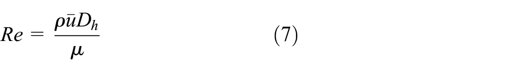
where ρ and μ are the density and viscousity of the test fluid, respectively. Dh is hydraulic diameter of the square channel, which equal to H. The
The pressure loss in the test section is shown in terms of the friction factor as equation (8)

where
The local Nusselt number, Nux, for the heat exchanger square channel is calculated as follow

where the local heat transfer coefficient is presented with hx, while k is the air thermal conductivity.
The average Nusselt number can be calculated by

where A is the heat transfer area of the SCHE.
The insertion of the SWS in the SCHE increases both heat transfer rate and friction loss. Therefore, the thermal enhancement factor (TEF) or thermo-hydraulic performance is presented to measure the thermal efficiency of the heating unit by comparing it at similar pumping power. The TEF is calculated as equation (11)

The Nusselt number and friction factor for the plain channel or smooth square channel are illustrated with Nu0 and f0, respectively.
Numerical validation of the computational domain
The physical model of the SCHE installed with SWS is validated to ensure that the numerical model has more reliance to presume flow topology and heat transfer mechanism of the present problem. The numerical validations are split into two sections: proof of the plain square channel and grid independence. The proofs of the smooth SCHE are done by relating between the values from the present computational design with the correlation values 23 for both Nusselt number and friction factor as depicted in Figure 2. As the figures, it is found that the present model gives higher Nusselt number around 0.05%, but performs lower friction factor around 0.7% when compared with the correlation data.

Validations of the smooth SCHE on Nusselt number and friction factor.
Grid independence, the five difference grid cells—80,000; 120,000; 180,000; 220,000 and 320,000—for the present model (α = 45°, BR = 0.20, VUA) are compared. As the results, the grid around 180,000–320,000 gives nearly values on both Nusselt number and friction factor for all Reynolds number. Therefore, the mesh around 180,000 is selected for the present examination to save time for calculation and computer resource. The grid check of the computational domain for the SCHE inserted with SWS is illustrated as Figure 3(a) and (b) for the Nusselt number and friction factor, respectively.

Grid independence for the SCHE inserted with 45° SWS at BR = 0.20 and VUA for (a) Nusselt number and (b) friction factor.
Numerical result
The numerical data are split into two segments: topologies in the tested section and performance analysis. The mechanism part will show the flow topology and heat transfer configuration when equipped the SWS in the SCHE. The λ2-iso surface, longitudinal vortex flow, and tangential velocity vector in y-z plane are selected to illustrate the flow topology, while the heat transfer mechanism is depicted by the distributions of temperature in crosswise plane and local Nusselt number on heat transfer surface. In the performance analysis part, the relations of the Nu/Nu0, f/f0, and TEF with the Reynolds number are plotted. The influences of the BR on friction loss, heat transfer rate, and thermo-hydraulic performance are showed with the plots of f/f0 versus BR, Nu/Nu0 versus BR and TEF versus BR, respectively.
Flow topology and heat transfer mechanism
The λ2 iso-surface in the SCHE inserted with SWS for α = 45°, BR = 0.20, and Re = 600 is stated as Figure 4(a) and (b), respectively, for VDA and VUA. The λ2 iso-surface is plotted to observe the core of the vortex flow or the center of the swirling flow in the SCHE inserted with SWS. As the figures, the center of the vortex/swirling flow is detected on the groove of the SWS for both arrangements. The vortex flow appears on both the upper and lower parts of the wavy surface. The strength of the flow on both arrangements seems to be close in this case, but the direction of the flow is not similar (considering from tangential velocity vector in the next figure). The vortex flow helps preferable fluid mixing between cold fluid at the center of the SCHE and hot fluid near the channel wall. The better fluid mixing leads to grow the heat transfer coefficient and thermal efficiency in the SCHE.

The λ2 iso-surface of the SCHE inserted with SWS at α = 45°, BR = 0.20, and Re = 600 for (a) VDA and (b) VUA.
Figure 5(a) and (b) display the tangential velocity vector in crosswise planes for the SCHE fitted with SWS for VDA and VUA, respectively, at Re = 600, α = 45° and BR = 0.20. As the figures, the SWS in the SCHE changes the flow structure. The SWS produces the vortex flow over the tested unit on both flow directions. The vortex flow includes four core swirling flows and small vortices close to the channel wall. Monitoring at the lower pair of the swirling flow, the counter swirling flows with common-flow-down and common-flow-up are found in the cases of VDA and VUA, respectively. The vortex flow is a significant factor to develop heat transfer coefficient and efficiency in the heating unit. The difference of the flow structure for VDA and VUA effects for the difference of the heat transfer behavior in the heating part.

Tangential velocity vector in transverse planes of the SCHE inserted with SWS at α = 45°, BR = 0.20 and Re = 600 for (a) VDA and (b) VUA.
The longitudinal vortex flow in the tested channel is plotted as Figure 6(a) and (b) for VDA and VUA, respectively, at Re = 600, BR = 0.20, and α = 45°. The longitudinal vortex flow is detected for all investigated cases, but the vortex strength of the flow is not identical. The longitudinal vortex flow helps a better fluid fusion in the test unit and interrupts the thermal boundary layer of the channel surface that is the cause for heat transfer coefficient and thermal performance enhancements.

Longitudinal vortex flow of the SCHE inserted with SWS at α = 45°, BR = 0.20, and Re = 600 for (a) VDA and (b) VUA.
The temperature diffusions in crosswise planes for the SCHE fitted with SWS are plotted as Figure 7(a) and (b), respectively, for VDA and VUA at Re = 600, BR = 0.20, and α = 45°. The temperature contour in transverse plane is an indicator to observe the change of the thermal boundary layer in the SCHE when inserted with SWS. In general, the blue layer (poor temperature) is sensed at the center of the channel, while the red layer (high temperature) is detected close to the channel wall for the smooth SCHE with no generator. The temperature distribution has changed when the wavy surface is inserted in the heating section. The blue layer spreads from the core of the unit, while the red layer nearby the channel wall seems to be thinner. The change of the thermal boundary layer is due to the bounce of the longitudinal vortex flow on the heat transfer surface. The change of the thermal boundary layer leads to the augmentation on heat transfer coefficient and thermal efficiency in the heat exchanger. The thin layer of the thermal boundary layer is detected for all sides of the channel walls for the VDA, while it is found on the left-right sidewalls of the VUA.

Temperature distributions in transverse planes of the SCHE inserted with SWS at α = 45°, BR = 0.20, and Re = 600 for (a) VDA and (b) VUA.
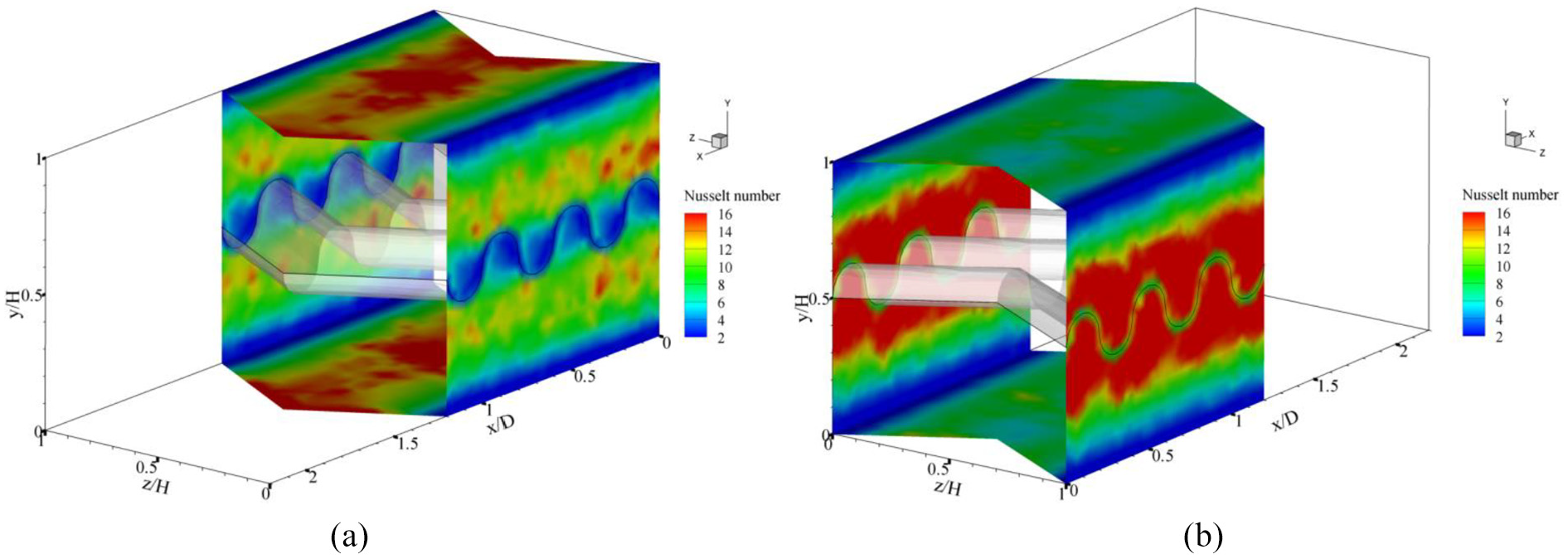
The Nux distributions of the channel walls of the SCHE when inserted with the SWS are depicted as Figure 8(a) and (b), respectively, for VDA and VUA at Re = 600, BR = 0.2, and α = 30°. The peak of heat transfer rate (red contour) is detected for all sides of the channel walls for VDA and on left-right sidewalls for VUA. The ultimate heat transfer rate is due to the impingement of the vortex flow which is created by the SWS. The heat transfer behavior in the heating unit with dissimilar flow attack angles of the SWS is found in similar pattern as presented in Figures 9 and 10 for the flow attack angles of 45° and 60°, respectively.

Local Nusselt number on heat transfer surface of the SCHE inserted with SWS at α = 30°, BR = 0.20, and Re = 600 for (a) VDA and (b) VUA.

Local Nusselt number on heat transfer surface of the SCHE inserted with SWS at α = 45°, BR = 0.20, and Re = 600 for (a) VDA and (b) VUA.
Local Nusselt number on heat transfer surface of the SCHE inserted with SWS at α = 60°, BR = 0.20, and Re = 600 for (a) VDA and (b) VUA.
The variations of the Nu/Nu0 at the sidewalls and Re for the SCHE inserted with 30°, 45°, and 60° SWS are illustrated as Figures 11–13, respectively. As the figures, the VDA performs higher heat transfer rate at the upper-lower walls of the SCHE, while the VUA gives greater heat transfer rate at the left-right walls of the channel for all flow attack angles. The reason is the VDA generates the vortex flow, which impinges on the upper-lower walls of the unit, while the VUA produces the swirling flow, which impacts on the left-right parts of the channel walls.
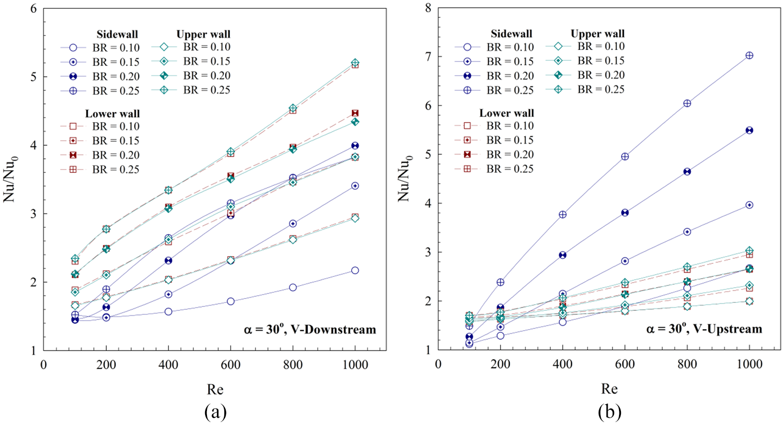
Nu/Nu0 with Re of the SCHE inserted with SWS at α = 30° for (a) VDA and (b) VUA.

Nu/Nu0 with Re of the SCHE inserted with SWS at α = 45° for (a) VDA and (b) VUA.

Nu/Nu0 with Re of the SCHE inserted with SWS at α = 60° for (a) VDA and (b) VUA.
Performance analysis
Figure 14(a)–(d) plot the relations of the Nu/Nu0 with the Reynolds number for the SCHE inserted with the SWS at BRs = 0.10, 0.15, 0.20, and 0.25, respectively. In general, the Nu/Nu0 rises when augmenting the Reynolds number for all examples. The presence of the SWS in the SCHE helps to increase heat transfer coefficient higher than the smooth channel for all examples (Nu/Nu0 > 1). The Re = 100 gives the lowest heat transfer rate, while the Re = 1000 shows the highest value for all cases. The variation of the Nu/Nu0 depends on the flow attack angle, BR value, Reynolds number, and flow direction.

Nu/Nu0 with Re of the SCHE inserted with SWS for (a) BR = 0.10, (b) BR = 0.15, (c) BR = 0.20, and (d) BR = 0.25.
For BR = 0.10, the VDA provides greater heat transfer rate than the VUA for all models. The 45° SWS gives the greatest heat transfer rate, while the 60° SWS performs greater heat transfer rate than the 30° SWS for both arrangements.
For BR = 0.15, the flow attack angles of 45° and 60° perform closely to values of heat transfer rate for both arrangements, while the case of 30° gives the lowest heat transfer rate on both VDA and VUA. The 45° and 60° perform very closely to values due to the fact that longitudinal vortex length and vortex strength may be in similar range.
At BRs = 0.20 and 0.25, the greatest of heat transfer coefficient is clearly detected at the flow attack angle of 45° and 60° for VUA when considering at Re > 400. The heat transfer rate is found to be nearly values at low Reynolds number (Re = 100–400). The placement of the SWS in the SCHE offers higher heat transfer rate than the smooth channel around 1.35–3.56, 1.39–4.23, 1.47–4.98, and 1.59–5.58 times, respectively, for BRs = 0.10, 0.15, 0.20, and 0.25.
Figure 15(a)–(d) report the relations of the f/f0 with the Reynolds number for the SCHE inserted with various flow attack angles and arrangements at BRs = 0.10, 0.15, 0.20, and 0.25, respectively. Generally, the friction factor increases when increasing the Reynolds number for all cases. The fitting of the SWS in the SCHE brings to higher friction loss than the plain channel with no turbulators (f/f0 > 1). The uppermost friction loss is found at Re = 1000, while the Re = 100 gives the reverse trend.

f/f0 with Re of the SCHE inserted with SWS for (a) BR = 0.10, (b) BR = 0.15, (c) BR = 0.20, and (d) BR = 0.25.
For BR = 0.10, the case of 30o gives nearly values of friction loss for both arrangements, while the model of 45o and 60o for VUA provides higher friction loss than the VDA when Re > 400.
For BR = 0.15, the VUA performs greater friction factor ratio than the VDA for all flow attack angles when Re > 400. The friction factor is found to be in nearly values when Re ≤ 400 for all flow attack angles.
For BRs = 0.20 and 0.25, the VUA gives greater friction loss than the VDA when Re > 200 for all flow attack angles. The 45o SWS performs the maximum friction loss, while the 60o SWS provides higher friction loss than the 30o SWS when Re > 200. At low Reynolds number (Re = 100–200) the friction factor ratios with various cases are found to be nearly values. The f/f0 is around 3.54–9.95, 4.27–13.93, 4.94–18.48 and 5.64–22.48 for the SCHE with the SWS at BRs = 0.10, 0.15, 0.20 and 0.25, respectively. In some cases, the f/f0 is found in similar value, because of the blockage configuration of the tested sections is equal (such as Figure 15(a) at Re = 1000 for 45o and 60o, VUA cases).
The variability of the TEF with the Reynolds number at different flow attack angles and arrangements of the SCHE inserted with the SWS at BRs = 0.10, 0.15, 0.20 and 0.25 are plotted as Figure 16(a)–(d), respectively. In general, the highest TEF is detected at Re = 1000, while the lowest values is found at Re = 100. The TEF tends to growth when augmenting the Reynolds number for all conditions. Almost cases, the insertion of the SWS in the SCHE leads to higher TEF than the smooth SCHE (TEF > 1). Considering at Re = 1000, the peak of TEF is detected in the case of 60o SWS with VUA, except for BR = 0.1, which is detected the greatest TEF at 45o SWS with VDA. The TEF of the SCHE is around 0.88–1.70, 0.85–1.78, 0.86–1.88, and 0.89–1.98, respectively, for BRs = 0.10, 0.15, 0.20, and 0.25.
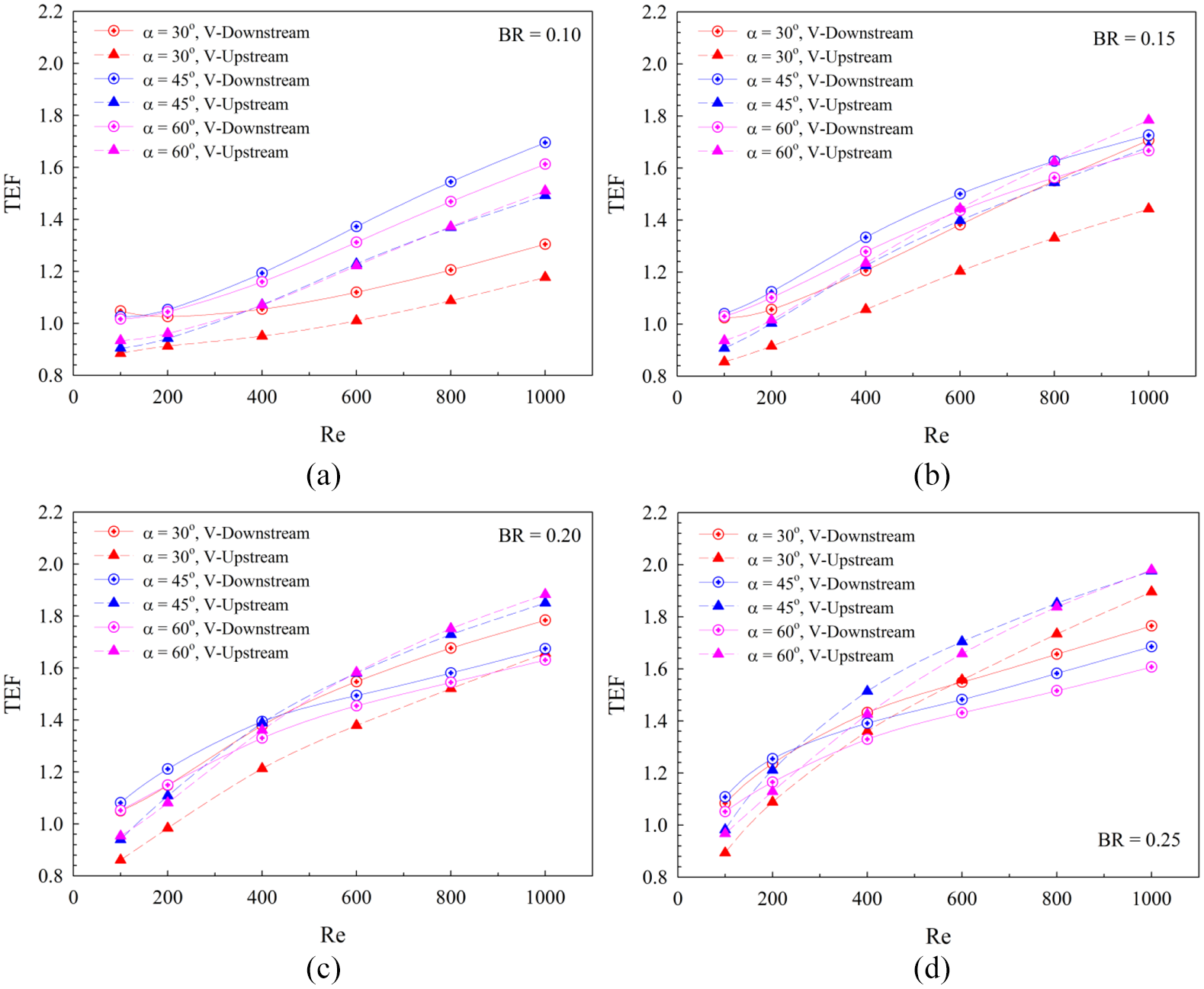
TEF with Re of the SCHE inserted with SWS for (a) BR = 0.10, (b) BR = 0.15, (c) BR = 0.20, and (d) BR = 0.25.
Figures 17–19 plot the relations of the Nu/Nu0 with BR at different Re values for the SCHE inserted with 30o, 45o, and 60o SWSs, respectively. In general, the heat transfer rate grows when enhancing the BR for all flow attack angles. The BR = 0.25 provides the greatest heat transfer rate, while the BR = 0.10 offers the contrary result. The reason is the BR = 0.25 can originate the strongest flow strength in the heating unit. The thermal boundary layer disturbance is clearly detected when the SWS is installed with high amplitude ratio in the test section.

Nu/Nu0 with BR of the SCHE inserted with SWS at α = 30° for (a) VDA and (b) VUA.

Nu/Nu0 with BR of the SCHE inserted with SWS at α = 45° for (a) VDA and (b) VUA.

Nu/Nu0 with BR of the SCHE inserted with SWS at α = 60° for (a) VDA and (b) VUA.
Figures 20–22 depict the deviations of the f/f0 with the BR with various Reynolds number for the SCHE installed with the SWS for the flow attack angles of 30o, 45o, and 60o, respectively. The f/f0 tends to rise with growing the BR for all models, especially, at BR = 0.20–0.25. The maximum friction loss is found at the BR = 0.25, while the conflicting result is detected at the BR = 0.10. In addition, the low amplitude ratio helps to drop the pressure loss in the tested unit.

f/f0 with BR of the SCHE inserted with SWS at α = 30° for (a) VDA and (b) VUA.

f/f0 with BR of the SCHE inserted with SWS at α = 45° for (a) VDA and (b) VUA.
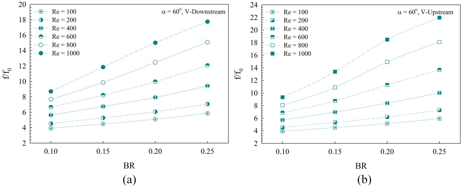
f/f0 with BR of the SCHE inserted with SWS at α = 60° for (a) VDA and (b) VUA.
Figures 23–25 plot the relations of the TEF with the BR at different cases for the heating section inserted with 30o, 45o, and 60o SWSs, respectively. For VDA, the best TEF is detected at BR = 0.20, 0.15, and 0.15 for the flow attack angles of 30o, 45o, and 60o, respectively, when considered at Re = 1000. For VUA, the maximum TEF is found at BR = 0.25 for all attack angles of the SWS at Re = 1000.

TEF with BR of the SCHE inserted with SWS at α = 30° for (a) VDA and (b) VUA.

TEF with BR of the SCHE inserted with SWS at α = 45° for (a) VDA and (b) VUA.

TEF with BR of the SCHE inserted with SWS at α = 60° for (a) VDA and (b) VUA.
Conclusion
Due to the importance for the improvement of the thermal efficiency in heating systems, the examination to increase heat transfer coefficient had been produced. Many researchers try to use on both experimental and numerical methods to solve these problems. The passive mode has been significantly considered to develop the heat transfer performance more than the active mode. Because of these methods, they do not need the external power or energy to push up the heat transfer coefficient of the systems.
In the present research, the numerical analysis on flow topology, heat transfer, and friction loss in SCHE equipped with the SWS are offered. The affectations of flow attack angles (α = 30°, 45°, and 60°), wavy surface arrangements (VDA and VUA), and amplitude ratios (BRs = 0.10, 0.15, 0.20, and 0.25) for heat transfer and flow structure are examined. The laminar region with the Reynolds number around 100–1000 is measured. The major findings for the present research are summarized as follows:
The installation of the SWS in the SCHE can expand the heat transfer coefficient and efficiency higher than the plain SCHE with no generator. However, the presence of the SWS in the SCHE not only rises in the heat transfer rate but also enhances pressure loss, especially, at highly values of BR and Re.
The SWS in the SCHE operates the longitudinal swirling flow over the tested unit. The longitudinal swirling flow helps a better fluid mixing and destroys the thermal boundary layer on the channel surface which are the reasons for heat transfer and thermal efficiency augmentations.
The strength of the swirling flow in the test section grows when augmenting the Reynolds number and amplitude ratio. The peaks of the friction factor and heat transfer rate are detected in the cases of the SWS with the flow attack angles of 45o and 60o. The 30o SWS in the heating unit help to decrease the pressure loss.
The manufacture of the SWS is easier than the other kinds of the vortex generators such as winglet, baffle, rib, and so on. Moreover, the installation of the SWS in the SCHE has more convenient when compared with the other methods such as the placement on the heat transfer surface. In comparison, the TEF of the present domain is in nearly range as the previous research, 19 but the maintenance, installation, and molding are simpler than the previous configuration.
The computational results on heat and flow structures in the SCHE can clearly explain the mechanism in the tested section. The knowledge of these mechanisms is an important data, which supports to produce the high performance heat exchanger.
Footnotes
Appendix 1
Acknowledgements
The funding of this work is supported by King Mongkut’s Institute of Technology Ladkrabang research funds (Contract no. KREF046006).The authors would like to thank Associate Professor Dr. Pongjet Promvonge, KMITL, for suggestions.
Handling Editor: James Baldwin
Declaration of conflicting interests
The author(s) declared no potential conflicts of interest with respect to the research, authorship, and/or publication of this article.
Funding
The author(s) disclosed receipt of the following financial support for the research, authorship, and/or publication of this article: This research was funded by College of Industrial Technology, King Mongkut’s University of Technology North Bangkok (grant no. Res-CIT0230/2019).