
Abstract
In order to reveal the gas–liquid two-phase flow pattern of inverted-umbrella aerator, the high-speed photography technology, particle image velocimetry, and Volume of Fluid model are employed to capture the free-surface dynamics and velocity distribution. The Computational Fluid Dynamics simulations are validated by experimental data and the results are in good agreement with experiment. The simulation results of flow field, streamline distribution, velocity distribution, free-surface deformation, and turbulence kinetic energy are analyzed at in time and at radial profiles sampled at several vertical positions. Back surface of each blade revealed the area of low-pressure, which can drag air into water directly from surface and thus enhance liquid aeration and oxygenation capacity. Lifting capacity of the inverted-umbrella aerator is enough to get the liquid at the bottom of the aeration tank accelerated toward liquid surface generating the hydraulic jump. As a result, liquid phase splashes capture portions of air promoting aeration of the solution. A clear circulation whirlpool is formed during the process. The circulation whirlpool starts at the bottom of the impeller moving upward along the plate until the outer edge of the impeller, which is close to the free surface. The circulation whirlpool indicates that the inverted-umbrella aerator plays a significant role in shallow aeration. The turbulence intensity created by the impeller gradually reduces with depth. The position (z = 0.65 H) is the watershed in the tank. The oxygen mass transfer mainly occurs in the layer above watershed.
Keywords
Introduction
Sewage biological treatment system has been widely used over the world to fight water pollution growing. 1 Oxidation ditch process is one of the main methods of sewage biological treatment system. It is one improved activated sludge treatment technology, which mainly drives sewage and activated sludge mixed to form a circulating flow by a surface aeration equipment. Aeration equipment is one of the key factors affecting efficiency, energy consumption, and stability of oxidation ditch. There are several different kinds of oxidation ditches, such as integrative oxidation ditch, orbital oxidation ditch, and carrousel oxidation ditch. Correspondingly, there are different aeration equipment, for example, rotating brush, rotating disk, inverted-umbrella aerator. 2 Inverted-umbrella aerator has the advantages of simple structure, oxygenation capacity, and high-power efficiency, and it can combine oxygenation and stirring functions. 3 Thus, it becomes the most used aeration equipment in oxidation ditch.
Over the past 30 years, the experimental study on inverted-umbrella aerator has been going. The studied parameters included impeller diameter, number and size of blades as well as submergence and water depth. The studies show that these variables affect aeration performance of inverted-umbrella aerator and reveal the relationship between oxygenation capacity, speed, diameter, and number of blades. 4 On the basis of experimental works, Ognean 5 determined the correlations between oxygen mass transfer rate, impeller diameter, rotation speed, and shallow volume. Established mathematical description to express dependence of oxygen mass transfer rate on power consumption. Cao 6 studied experimentally oxygen transfer of high-power surface aerator as a function of mixing speed and immersed depth.
In order to understand better hydrodynamics characteristics of the inverted-umbrella surface aerator, the structure of inverted-umbrella aerator and the impeller form were studied. Four inverted-umbrella aerators of different configuration were developed to find out the variations in overall oxygen transfer coefficient and aeration efficiency. Thakre et al. 7 developed four inverted-umbrella aerators to find out the variations in overall oxygen transfer coefficient and aeration efficiency by varying the parameters like rotation speed, depth of immersion, and blade tip angle. Pan 8 studied the oxygenation performance of several different types of inverted-umbrella aerator and their influence on the oxygenation capacity varying blade angle and number of blades to analyze the impeller design.
Zhou et al. 9 studied the power efficiency of the aerator. For the purpose of studying the optimal value of the power efficiency of the inverted-umbrella aerator, the rotation speed and immersed depth of the stirrer were changed and the power efficiency of the inverted-umbrella aerator under different conditions was measured. The experiment results revealed the correlations between power efficiency, immersion depth, and mixing speed.
Development of high-performance computers and continuous improvement of numerical methods and models make Computational Fluid Dynamics (CFD) a powerful tool actively used to optimize aeration systems.10–13 Rao and Kumar 14 studied the mass transfer coefficient, power efficiency, power number, and other parameters numerically and experimentally. The researchers found that the power efficiency of the inverted-umbrella aerator was not static, and higher power efficiency can be achieved by adjusting the power input of the inverted-umbrella aerator. Deshmukh and Joshi 15 measured the mass transfer coefficient (kLa) and power number (Np) of the inverted-umbrella aerator with different submerged depths. They presented relationship between the mass transfer coefficient, power number, gas hold-up, and flow pattern.
Kumar and Rao 16 simulated the turbulence energy dissipation rate of the liquid around the inverted-umbrella aerator by VisiMix software and found that the oxygen mass transfer rate was only related to the energy dissipation rate. Gandhi et al. 17 extracted the characteristics of the pressure pulsation signal by using the chaos analysis technique, which included estimation of Lyapunov exponent, correlation dimensions, and Kolmogorov entropy. Shi and Wang 18 established nonlinear relations between chaotic invariants and kLa. The numerical simulations of three aerator types of different structure were presented to analyze the stirring effects and power efficiency of the aerators. Xing et al.19,20 designed and simulated the inverted-umbrella aerator blade, which was arranged according to the variable helix angle of the logarithmic spiral line. Using simulation, based on fluid-structure interaction and finite element methods, the optimal design of the aerator blade has been found.
Operation of inverted-umbrella aerator is a challenging task, since it involves complex phenomena taking place in multiphase media, such as hydraulic jump, gas entrainment, and wave breaking. Although there are studies on inverted-umbrella aerator using numerical simulation methods, some scholars employed rigid cover or wall surface to deal with the free surface that ignores surface fluctuations. It contributes to deviation between simulation results and experimental data.
Therefore, the internal flow characteristics and operation modes of inverted-umbrella aerator are studied in this research, which helps to optimize structure of the aerator and control hydrodynamic characteristics in oxidation ditch. The outcomes are to provide valuable data for the design of oxidation ditch. In this article, high-speed photography technique and Volume of Fluid (VOF) model with Level set are employed to study the gas–liquid interface motion dynamics as well as multiphase flow pattern in an aeration tank driven by an inverted-umbrella aerator.
Test system
The test object is an inverted-umbrella aerator wholly submerged in a circular aeration tank. The diameter of the inverted-umbrella aerator impeller is only 150 mm, so the hole connected with the shaft is processed by wire cutting technology. The aeration tank is made of plexiglass with a diameter and a height of 600 mm. And, the liquid level of the aeration tank is 200 mm. The aeration tank was designed without baffles, so as to reduce the factors affecting stirred flow field. Initially, the impeller was placed just below the liquid surface, correspondingly to submerged depth of 0 mm. And, it rotates clockwise around the central axis with a rotation speed of 240 r/min, the Reynolds number is 1.41 × 10⁵.
The geometric details of the inverted-umbrella type impeller are shown in Figure 1. And, the schematic diagram of test object is shown in Figure 2.

Inverted-umbrella type impeller.

Model diagram.
High-speed photography
To study the free-surface behavior and internal flow characteristic during the operation of inverted-umbrella aerator, the high-speed photography and particle image velocimetry (PIV) system were used, as shown in Figure 3. The testing apparatus mainly consist of inverted-umbrella aerator, aeration tank, frequency conversion cabinet, servo motor and lifting device, LED lights, high-speed cameras, and PIV system. The frequency conversion cabinet is used to control the speed of rotation. The inverted-umbrella aerator is fixed on a lifting device, and the immersion depth of the impeller is adjusted by servo motor.

High-speed photography and PIV set-up.
The main testing equipment of high-speed photography is the high-speed camera produced by IDT company, the model of which is Motion Pro Y4LM-8. During the test, it is used simultaneously with the acquisition software of Motion Studio to complete image acquisition and transmission. The maximum resolution of the camera is 1024 × 1024, and the pixel size is 14 × 14 μm. The shooting frequency was set to 720 Hz. During the experiment, for clearly capturing the free surface, LED lights are located in the directions of above and below liquid surface.
PIV
The PIV system mainly include light source, optical arm, charge-coupled device (CCD) camera, and synchronizer. The light source is Nd:YLF (Neodymium-Doped Yttrium Lithium Fluoride) laser with laser beam intensities adjusted to 30 mJ per pulse. A light-guiding optical arm directs the pulsing laser beams to the test area. When capturing, the relative position and height of the camera and laser to the aeration tank is adjusted to ensure the focus position of laser waist and lens fall in the test area. Al2O3 particles are seeded in the water, whose average diameter is 1 μm. A CCD camera perpendicular to the laser sheet is used for particle image capture. A synchronizer is adopted to ensure image acquisition synchronized with respect to the impeller rotation.
For PIV test, the calibration is especially important. The object marked with scale was placed on the smooth surface of sheet light. And, a lamp is used as supplementary lighting source to make the scale lighter. Adjust the camera’s aperture, focus, and body angle to capture the image so that the single image is evenly focused. Select the marked starting point and ending point on the image, use the software calibration function, input the corresponding object size, and complete the calibration. The interval time between two frames was finally set to 600 μs. Because the inverted-umbrella aerator and aeration tank is symmetrical, only one phase condition is measured with pulse delay time of 0.25 s.
Computational method
The fluid domain of numerical model is divided into two parts, that are rotating domain and outer static domain. The computational domain is shown in Figure 4, where H and z represents the liquid height and vertical position, respectively. A structured array of hexahedral mesh elements is applied to the model using ICEM software. In order to check the influence of mesh element number on the free surface, liquid surface capture capacities under elements of 0.58, 1.15, 2.30, and 2.80 million has been compared. When the total grid number is 0.58, 1.15, 2.30, and 2.80 million, the maximum height of hydraulic jump is 41 mm, 43 mm, 45 mm, and 47 mm respectively; 2.30 million and 2.80 million is better than 1.15 million. And, there is basically no difference between the free surface of 2.30 and 2.80 million.

Inverted-umbrella aerator computational domain: (a) computational domain and (b) rotating domain.
Then, 2.30 million has been finally chosen considering computation time. Fine elements are concentrated in the regions of the free surface and inverted-umbrella aerator to capture detailed free-surface fluctuation as well as the flow around the stirrer. The grid arrangement is shown in Figure 5.

Generated grid.
The finite volume method was used to simulate gas–liquid mixing. The VOF with Level set model has been successfully used by many researchers for two-phase problems.21,22
The calculation has the following main governing equations.
The continuity equation is

The momentum equation is
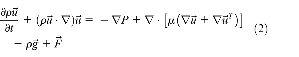
The volume fraction continuity equations are

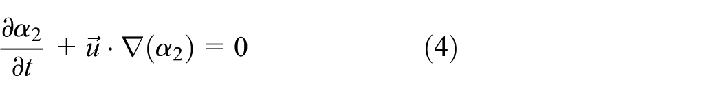
where α1 represents the volume fraction of liquid, α2 represents the volume fraction of air, and α1 + α2 = 1. ρ represents the density of liquid. µ represents the dynamic viscosity coefficient of liquid. t represents the time.
The numerical simulation was performed using FLUENT 15.0. The mixing speed 240 r/min creates turbulent flow. Therefore, VOF with Level set was applied to simulate liquid surface motion and Renormalized Group (RNG) k–ε turbulence model was used to simulate turbulent flow. The effect of swirl on turbulence is included in the RNG k–ε turbulence model, enhancing accuracy for swirling flows. 23
The impeller rotation is modeled by sliding mesh technique. The initial distribution of gas–liquid two-phase was achieved by Patch function.24,25 To solve pressure–velocity equation, Semi-Implicit Pressure Method for Pressure Linked Equations (SIMPLE) algorithm in conjunction with “Geo-Reconstruct” model to calculate volume fraction were used. Residuals are defined as the imbalance in each conservation equation summarized at each iteration. The calculation has converged when the scaled residuals went below 10−4. Courant number is an important index for VOF transient calculation. The smaller the value is, the more the calculation is stable. But the convergence takes more time. In this case, the initial time step was 6.944 × 10⁻⁵ s (the time required for the impeller to rotate 0.1°) the global float is less than 5. Then the time step has been gradually increased after the calculation were stable until time step has been increased 10 times, the global float was maintained at 7.
Verification of simulation reliability
Comparison on the vertical view of free surface
When the motor was run by the frequency controlling cabinet (the stable running frequency of the motor was 8 Hz), there was an algorithm of speed adjustment from 0 to the set value of rotating speed, which was accompanied by impeller acceleration. Therefore, during the test, the simulation results are divided into two states: start-up and stable rotation. Only the free-surface deformation at the stable rotation is considered in this article.
Figure 6 shows the top view of the free-surface deformation near the aerator, which are obtained by the CFD simulations and the high-speed photography experiment, respectively. It can be seen from Figure 6 that the free-surface deformations of the simulation and experiment are similar, which supports the numerical simulation qualitatively. The liquid in the pool flows upward through the gap of the impeller and enters into the upper side of the plate. Then, under the effect of superposition of inertial and gravitational forces, the liquid in the specific flow channel of the plate would slide into the next flow channel. Finally, the liquid is ejected out from the blade leading surface through the upper side of the plate, which is called hydraulic jump. The liquid splashed from the hydraulic jump is mainly from the flow channel of the plate. At the same time, it can be seen that the velocity of the liquid passing through the impeller gap is relatively small. As the impeller rotates, the velocity is increasing gradually and reaching the maximum speed when the liquid leaves the leading surface of the blade. Then, the liquid disperses into the fine droplets and falls back into the water.

The planform of free surface: (a) simulated free surface and (b) photo of free surface.
Comparison on the upward view of free surface
Figure 7 shows the relative pressure contour of the inverted-umbrella aerator. It can be seen from Figure 7 that the relative pressure of the blade leading surface is higher than that of the trailing surface. The low-pressure area appears in the trailing surface near the middle of the blade.

Relative pressure contour of impeller.
Figure 8 shows the bottom view of the free-surface deformation near the inverted-umbrella aerator obtained by simulation and high-speed photography.

The bottom view of free surface: (a) simulated free surface and (b) photo of free surface.
In Figure 8(a), a large amount of air is accumulated near the blade tip of the trailing surface of the blade. Moving from the blade tip toward center of the aerator gas volume is gradually decreasing. Finally, with a triangular shape, a three-clinging cavity is created stably behind the blade at this speed. The experiment also captured this phenomenon, as shown in Figure 8(b). The phenomenon shows that the inverted-umbrella aerator has a strong entraining ability, which can directly carry the air into the water to enhance its aeration and oxygenation capacity.
We can see that the numerical result is in a good agreement with the experimental data, and the CFD model used in this study is qualitatively validated.
Comparison on the experimental and simulated streamline
Figure 9 shows the experimental and simulated streamline of the inverted-umbrella aerator. It can be seen that both the experiment and the simulation have similar internal flow trends. Because of the lifting capacity of the inverted-umbrella aerator, a clear circulation whirlpool is formed in the vertical cross-section. The whole liquid flow pattern generally corresponds to that of radial agitator. The liquid is pushed in radial direction to the wall and moves down to the bottom of the aeration tank. Finally, the liquid rises up to the free surface driven by the lifting capacity.

Streamlines and contour in vertical cross-section: (a) simulated result and (b) experimental result.
Comparison on the experimental and simulated velocity
In order to analyze the velocity distribution of the aeration tank in axial direction at different depths, radial profiles were sampled at different vertical position to monitor velocity. The radial distance r/R is 0.07, 0.13, 0.2, 0.27, 0.33, 0.4, 0.47, 0.53, 0.6, 0.67, 0.73, 0.8, 0.87, and 0.93. The vertical positions are schematically shown in Figure 10.
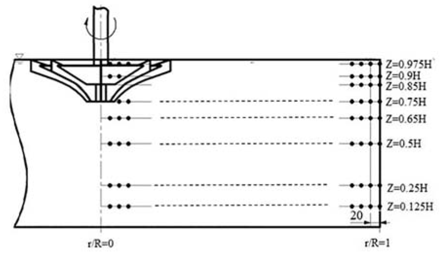
Schematic representation of sampled radial profiles.
Figure 11 shows the axial velocity distribution at different depths. In the impeller domain (r/R < 0.25), the fluid velocity increases first then decreases in radial direction, and reaches the maximum velocity at the tip of the impeller. The simulation results shown in the figure are in good agreement with the PIV results.
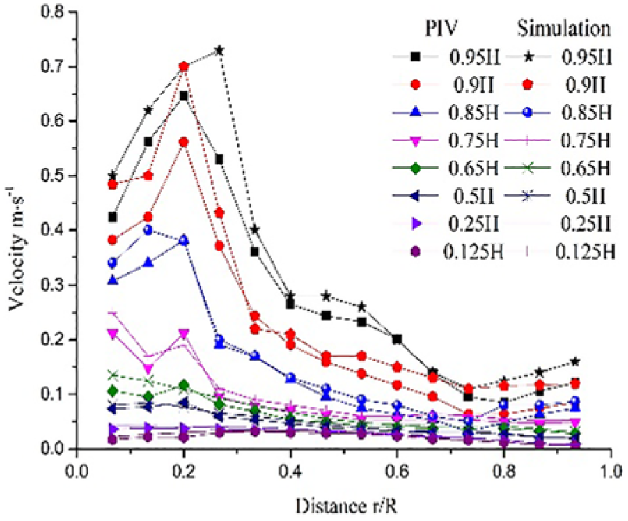
Axial velocity at different depth.
Due to the rotation of the impeller, there is maximum axial lifting speed at z > 0.75 H. The inverted-umbrella aerator acts as a surface aerator mainly affecting the liquid near the surface and has little effect on the liquid for the depth lower than 0.75 H, which leads to the lowest velocity.
Analysis of numerical simulation results
Streamline distribution
Figure 12 shows the simulation results of free surface and the three-dimensional streamline of the inverted-umbrella aerator. It can be seen from the figure that the liquid at the bottom of the aeration tank is gathered toward rotating axis below the stirrer. The liquid moves up to the impeller under the influence of the aerator lifting capacity, and the streamlines move at the bottom of the aeration tank in clockwise direction following the impeller motion. The liquid velocity at the bottom of the aeration tank is gradually increasing along the direction of the streamlines resulting in a hydraulic jump in radial direction.

Three-dimensional streamline diagram of the flow pattern created by the inverted-umbrella aerator.
In the vicinity of the impeller, the liquid is subjected to a large shear action, and the turbulent kinetic energy and the flow velocity are the biggest in this region, leading to the high transport capacity of the air. The oxygen mass transfer rate is the highest here accordingly. The liquid velocity is lower in the bottom of the aeration tank, the streamlines change smoothly, and the turbulence intensity is low. Depending on mixing speed, impeller vertical position, and shallow depth, there could be even a velocity stagnation zone in the bottom of the aeration tank.
Flow field in vertical cross-section
Velocity distribution at different time
The liquid domain is mainly considered in this section. The velocity contours and streamlines of the vertical cross-section are shown in Figure 13. It can be seen that the area of fluctuation near impeller gradually expands, and the fluid diffuses in the vertical and horizontal directions simultaneously as time goes by. The circulation whirlpool appears near the bottom of the impeller at 0.125 s and moves obliquely upward along the lower side of the plate over time. The circulation whirlpool appears right at the outer edge of the impeller at 0.5 s. Then, the circulation whirlpool moves outward in radial direction until the time reaches 1.25 s, by which it stabilizes in a certain position. Between 1.25 and 1.75 s, the shape of the streamlines below the free surface changes slightly. So, the liquid flow hydrodynamics seem to have reached steady state.

Velocity contours and streamlines diagram in vertical cross-section at different time: (a) t = 0.125 s, (b) t = 0.25 s, (c) t = 0.5 s, (d) t = 0.75 s, (e) t = 1 s, (f) t = 1.25 s, (g) t = 1.5 s, and (h) t = 1.75 s.
Analysis of stable flow field
From the above analysis, it can be concluded that the steady operation of the inverted-umbrella aerator can be divided into three stages. At the initial operating stage, the impeller discharges the liquid above the plate because of rotating motion. The free-surface deformation appears above the impeller, and the circulation whirlpool starts at the bottom of the impeller. During the second stage, the liquid flows into the upper side of the plate through the gap, and the circulation whirlpool moves obliquely upward along the lower side of the plate. At the last stage, the whole aeration tank is stirred due to the effect of the impeller rotation. Then, the free-surface fluctuation becomes stable and the circulation whirlpool is formed, which originates at the outer edge of the impeller. The streamline and liquid phase volume fraction in the vertical cross-section section of the aerated tank is shown in Figure 14 at t = 10 s.

Streamlines and contour of liquid volume fraction in vertical cross-section.
It can be seen from Figure 14 that the circulation whirlpool, formed by aerator, is very close to the free surface, and it is slightly different from the flow pattern created by radial stirrer fully submerged. This indicates that the inverted-umbrella aerator plays a significant role in stirring the shallow liquid flow. In addition, it can be noticed from the figure that the high fraction of gas captured in water locates near the walls of the tank. This is due to the fact that with the rotation of the impeller, the liquid in the tank is ejected along the blade radially (as seen in areas A in Figure 14). When the ejected liquid splashes fall back, they capture some amount of gas and drag them under water (as seen areas C in Figure 14).
Analysis of free-surface deformation at different time
The interface with the 0.5 gas phase volume fraction is chosen as the free surface. Figure 15 shows the free-surface deformation and velocity distribution contours of some representative moments during the aeration process. Figure 15(a) is the initial free surface where inverted-umbrella impeller is just submerged below the free surface and the surface remains calm. Figure 15(b) demonstrates the changes of the free surface of inverted-umbrella aerator running at 0.125 s where the impeller has passed half cycle. It can be seen from the figure that the free surface first changes around the impeller due to the high-speed rotation. Because of the effect of the inherent inertia, the surface deformation is relatively smooth and presents six slightly elevated crests. The blade vertex closest to the free surface has the maximum mean velocity. Due to the surface tension, the liquid above the impeller shows regular deformation. The surface away from the impeller has no visible change.

Velocity fields in isosurface of gas–liquid interface at different times: (a) t = 0 s, (b) t = 0.125 s, (c) t = 0.25 s, (d) t = 0.5 s, (e) t = 0.75 s, (f) t = 1 s, (g) t = 1.25 s, (h) t = 1.5 s, and (i) t = 1.75 s.
Figure 15(c) shows the changes of the surface around the aerator running at 0.25 s. It reveals that during this period there is a process of discharging the liquid above the plate. At this time, the lifting capacity of the impeller is weak, and only small amount of liquid flows into the upper side of the plate through the gap of the impeller. The surface near the impeller appears to have inverted cone shape. The surface deformation expands. Major part of the free surface remains calm since the runtime is short.
Figure 15(d)–(f) shows free-surface deformations of inverted-umbrella aerator running from 0.5 to 1 s. They demonstrate that the lifting capacity of the impeller is gradually enhanced with the rotation of the impeller. The upper side of the plate is filled with liquid again, and the liquid hydraulic jump in the aeration tank is noticeable. The liquid is ejected obliquely upward along the blade leading surface and falls back to the surface due to gravity. On the horizontal cut planes, the liquid which is ejected moves as a logarithmic spiral. The dominating part of the free surface changes slightly after 0.5 s. There is also slight liquid-level fluctuation at the wall of the aeration tank when the time is between 0.5 and 1 s, hence obvious fluctuation occurs in the free surface. Although the surface deformation and velocity near the impeller have little changes, the fluctuating of the free surface near the impeller spreads to the walls.
Figure 15(g)–(i) displays free-surface deformations in time from 1.25 to 1.75 s. As it can be seen from the figure, the fluctuations are drastic. The reason is that the aeration tank is a circular space, the liquid flows to the wall at a certain velocity under the action of the rotation. The fluid is constrained by the walls, then a portion of the liquid flips due to impact force with hitting the wall. The other portion of the liquid flows along the wall and flows toward the aerator under the action of the centripetal force. When the reflux collides to the liquid that diffuses toward the wall, the surface fluctuation turns drastic. At the same time, it can be found that the shape of the free surface and the velocity near the impeller are basically stable between 1.25 and 1.75 s. The free-surface deformation away from the impeller hardly changes.
Analysis of turbulence
Turbulent kinetic energy is one of the most important variables because it is a measure of the intensity of turbulence. The greater the turbulent kinetic energy, the more intense the turbulence of the liquid is. According to the theory of surface renewal model of oxygen mass transfer, the increase of turbulent kinetic energy can accelerate the update of interface and shorten the residence time of the surface, which can increase the oxygen mass transfer coefficient. Figure 16 shows the turbulent kinetic energy contours of the cross-section of the aeration tank at different depths under stable operating condition. It can be seen from the figure that the turbulent kinetic energy close to the impeller is larger, which indicates that the liquid is prone to generate impact, whirlpool or reflow, and causes turbulence of the liquid in arbitrary directions. In addition, the action range of impeller gradually reduces with the depth increasing and so does the turbulence intensity. The depth 130 mm is a watershed, below which there is little turbulent kinetic energy. It can be concluded that the shallow liquid gets the most energy, generates the strongest turbulence, and oxygen mass transfer also mainly occurs in this layer.
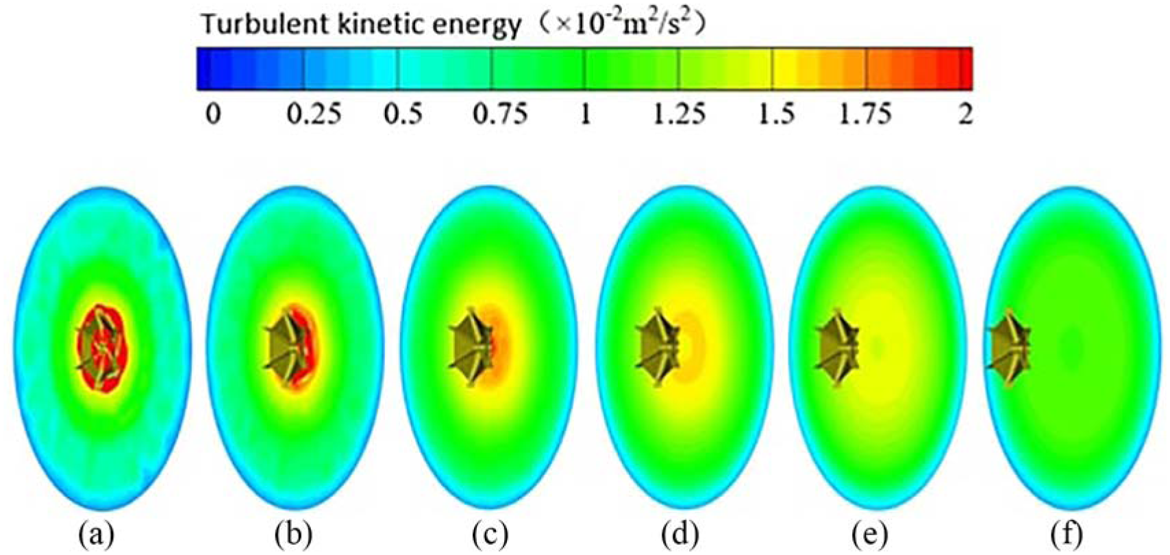
Contours of turbulent kinetic energy at different depths at 1.75 s in horizontal cross sections: (a) z = 180 mm, (b) z = 170 mm, (c) z = 150 mm, (d) z = 130 mm, (e) z = 100 mm, and (f) z = 50 mm.
Conclusion
Based on the high-speed photography technique and CFD modeling, the free-surface deformation in the aeration tank driven by the inverted-umbrella aerator is studied. The deformation pattern of the free surface as well as the evolution of the internal flow field and the flow pattern are analyzed. The following conclusions are obtained:
The free-surface deformation, which is obtained by numerical simulation, agrees well with the results of high speed-photography. Therefore, the CFD model used in this study can predict surface fluctuation with reasonable accuracy. The relative pressure of the blade leading surface is higher than the trailing surface. The trailing surface appears in obvious low-pressure area, which can directly carry air into the water and enhance aeration and oxygenation capacity.
The working process of the inverted-umbrella aerator can be divided into three stages. At first stage, the liquid above the plate is discharged through the impeller rotation, and the liquid surface deformation first appears above the impeller. Then, the liquid goes into the upper side of the plate through the gap of the impeller, and the deformed free surface is moved toward the wall. Finally, the whole surface fluctuates in the tank. The circulation whirlpool under the free surface corresponds to the surface change. The circulation whirlpool first appears at the bottom of the impeller and moves obliquely along the lower side of the blade.
The liquid at the bottom of the aeration tank is gathered on the impeller axis direction. The liquid moves up to the impeller field with the action of the impeller lifting capacity, and the streamline direction at the bottom of the aeration tank is clockwise. The circulation whirlpool, created by impeller motion, appears at the outer edge of the impeller initially and moves outward in radial direction. Between 1.25 and 1.75 s, the flow field is no longer changing, which indicates that the circulation whirlpool is developed and steady.
Due to shearing action, the turbulence kinetic energy and flow velocity are the largest in the vicinity of the impeller which leads to the strong transport capacity of the air. Accordingly, the oxygen mass transfer efficiency is the highest here. The velocity increases first and reaches its maximum at the outer diameter of the impeller, then decreases as the distance increases in radially. The mixing force of impeller gradually subsides with depth, and so does the turbulence intensity. The position where the depth is 130 mm is a watershed. For the depth lower than 130 mm, the impeller has minor effect on the liquid, which leads to the phenomenon that the liquid velocity is lower in the bottom of the aeration tank, the streamline changes smoothly and the turbulence intensity is also low there.
Footnotes
Handling Editor: James Baldwin
Declaration of conflicting interests
The author(s) declared no potential conflicts of interest with respect to the research, authorship, and/or publication of this article.
Funding
The author(s) disclosed receipt of the following financial support for the research, authorship, and/or publication of this article: This work was supported by National Key Research and Development Program of China (Grant No. 2016YFB0200901); National Natural Science Foundation of China (No. 51879122, 51509111, 51779106); China Postdoctoral Science Foundation (2017M611721); the association innovation fund of production, learning, and research (BY2016072-01); Zhenjiang key research and development plan (GY2017001, GY2018025); the Open Research Subject of Key Laboratory of Fluid and Power Machinery, Ministry of Education, Xihua University (szjj2017-094, szjj2016-068); Sichuan Provincial Key Lab of Process Equipment and Control (GK201614, GK201816); the Advanced Talent Foundation of Jiangsu University (15JDG052); and a project funded by the Priority Academic Program Development of Jiangsu Higher Education Institutions (PAPD), Jiangsu top six talent summit project (GDZB-017).