
Abstract
With the tremendous growth of science and technology in the world, the silent submarine has been an interesting research topic for many years. What is of equal interest is how to produce a high-speed submarine that limits noise to minimise detection from the enemy. In this study, we investigated the combination of a propeller and a duct so that when a submarine is operated, it minimises as much as possible the noise without affecting the speed of the submarine. The goal of installing the duct outside the propeller is to reduce the noise and loss of thrust simultaneously. The purpose of this article is to investigate the variation of the magnitude of the noise and thrust that occurs when a submarine propeller is operated in six different types of ducts. The research method is to use the large eddy simulation method with the cavitation model and then to calculate the result using the finite volume method. The study found that Ducts 1 and 4 have a better noise reduction effect and better propulsion than the other four ducts. Among them, Duct 4 has the best noise reduction effect, and Duct 1 provides the maximum propulsion. In all of the computation examples herein, the cavitation phenomenon did not occur. In the future, we will continue to study the growth and decline of related physical quantities with various types of propellers and ducts.
Introduction
The propeller has already been studied and experimentally tested for nearly 80 years and there are many causes that lead to noise formation, including machinery vibration, auxiliary machinery and propeller rotation. Research has assessed ways to reduce the noise from the propeller with the acoustic cavitation model using the large eddy simulation (LES) method.1,2 The rotation speed of the propeller is one of the principal factors bringing acoustics from the submarine. The imperfections in the entry flow to the propeller and the turbulence on the blade surfaces of the propeller are caused by the disturbing forces.
With unavailable data, in generic submarine propeller experiments, Di Felice et al. 3 studied the wake of the propeller with several loads. Acoustic responses on the submarine hull were shown by Mauro and Nicole. 4 The noise in the submarine needs to be reduced; therefore, at present, the propeller of the submarine is bigger with more blades than the ship propellers. 5 The submarine always has a larger diameter propeller and has more number of blades than the ship propeller to decrease the noise and maintain thrust quality.
Using the research data, we used the LES method to calculate the acoustic model combined with cavitation to analyse the effect of installing a duct on the submarine. The simulated dynamic cavitation 6 calculation is based on the LES model.7–12 This model setup uses a single-fluid, two-phase mixture description of the cavitation combined with a finite rate mass transfer model. 13 The computational output is for a full submarine propeller using Ffowcs Williams–Hawkings (FW-H) equations14,15 to compute with unsteady flow.
The computational model is the submarine DARPA Suboff AFF8 16 and the propeller INSEAN E1619 with different shapes of ducts. The shape of the duct used on the submarine propeller affected the noise reduction and reduced the thrust loss. 17 The consequence is shown that computationally agreed well with the experimental data, and the numerical method has good accuracy to predict the hydrodynamic performance of a propeller submarine. We use two software packages, ANSYS and MATLAB, for the computational model to determine which duct will make the submarine run better.
Methods
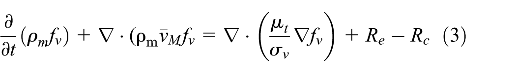
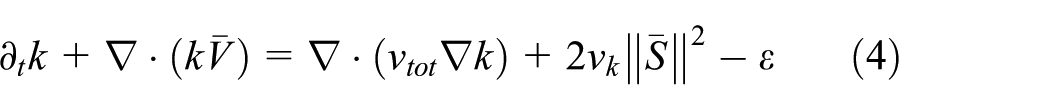
First, we examine the way to simulate the flow field around the propeller. Some of the various components of the plan of action have been presented in the reference paper. The governing equation for the numerical calculations in Ansys 15 Fluent is as follows

where xi is the tensor form of the axis coordinates, vi is the velocity,
When the liquid phase changes to the vapour phase at a certain low-pressure region, cavitation occurs. There are two types of vaporisation. The first is the well-known process of vaporisation by increasing temperature, and the second is when the pressure is reduced at a nearly constant temperature. The cavitation phenomenon can occur anywhere on the submarine with low pressure or high local velocity, and the propeller is an important source of cavitation18,19 due to the high velocity around its blades. Thus, vibration and erosion on the propeller create more noise on the blade.
In this study, the propeller speed is 20 rps. The radius of the propeller is 0.2425 m, and the saturated vapour pressure is 2368 Pa. The cavitation

where
where
The FW-H equations are formulated from the analogy acoustics by Lighthill 23 and are capable of predicting sound generated by equivalent acoustic sources such as monopoles, dipoles and quadruples. The FW-H equations are derived from Navier–Stokes equations. The FW-H equations have been presented by Özden et al. 24

where ui is the flow velocity in the zi direction, un is the flow velocity normal to the surface (f = 0), Vi is the surface velocity component in the zi direction, Vn is the surface velocity component normal to the surface, δ(f) is the Dirac delta function, H(f) is the Heaviside function,

The distribution of the sources on the blade can be represented like the solution of the wave. All model computations used the FW-H formula to estimate the acoustic results. The boundary conditions can be defined with the proposed conditions: prescribed velocity at the inlet of the wall equal to 1.68 m/s, pressure equal to zero at the outlet section, slip at all computational domain and no-slip conditions enforced on the propeller and shaft surfaces.
In this research, using one non-dimensional wall for a wall boundary condition flow, that is, y+, is defined as follows

where
Validation and geometry simulation model
The methodology to calculate the noise of the propeller is solved with the LES strategy using the FW-H equation to measure the acoustic results. The model in this study is used for validation, where the propeller diameter D is 0.3 m, the rotational speed is 978 r/min and the advanced speed is 3 m/s.
The cylindrical computation domain diameter is 3D. The length of the inlet domain is 6D with the propeller computation model, and the cylinder domain with the submarine propeller is 1.5L (L: length of submarine) in diameter and 9L in length for the cylinder domain. The results of the computations from the receiver points are located 1 m from the centre point of the propeller, as shown in Table 1, with the coordinate centre of the propeller at (0, 0, 0).
Coordinates of receiver points, which reveal the acoustic results.

The advance coefficient value is J = 0.61 due to the unsteady flow to solve the acoustic model used LES method to computation. Acoustic solutions around the propeller within four receiver points are shown in Figure 1. The result we obtained is close to the experimental result presented by Özden et al. 24 The outcome at a low frequency is greater than the experimental results but are much smaller than the results from Özden.

Comparison of the numerical results with the experimental results from Özden et al. 24
The cavitation model exploring the LES method can be applied to predict the noise owing to the shape of the duct and to determine which duct can reduce the noise and thrust losses from the tip flow. The duct can control the flow velocity and the flow pressure, but the duct shape has an effect on the efficiency of the submarine propeller. From the duct shapes previously presented by Serdar et al. 25 and Koronowicz et al., 26 we assess six duct shapes to evaluate the computational effect on the submarine, as shown in Figure 2. The result shows which duct shape is able to be used with the submarine propeller to reduce the noise and thrust losses more efficient than other options.
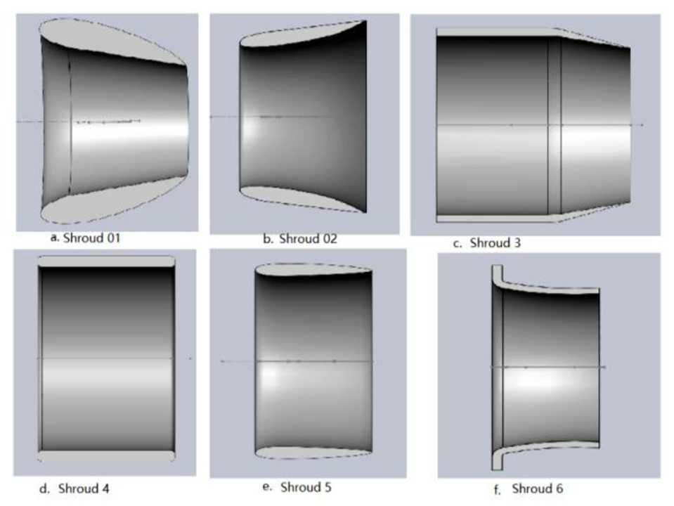
Duct models.
All of the simulation models were made with DARPA Suboff AFF8,16,27 which is a generic submarine with a length of 4.36 m and maximum cylindrical diameter of 0.508 m, as already presented by Özden et al. 24 The propeller type is INSEAN E1619.
On the mesh generation, the computational domain has been divided into two main parts: the first part is the centre of the block, which has a propeller, duct and submarine. The structural mesh is used to divide this part into very small elements, about 0.8 million cells, for computation (Figure 3). The second part is the cylinder outside of the flow domain, which has a coarse mesh for the computation.
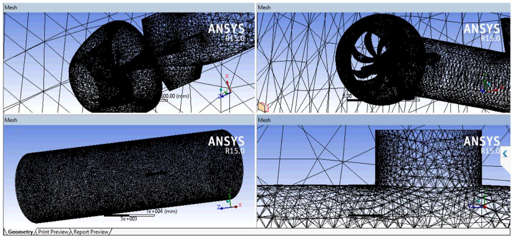
Calculation of the mesh domain of submarine computation model.
The wall y+ is used to evaluate the mesh of the model; it describes how coarse or fine a mesh is for a flow pattern. Figure 4 shows the contours of wall y+ on the propeller blades, which is 40 to 60. On the edge of the propeller, the wall y+ is 2 to 4. This indicates that the mesh cell part is well resolved.
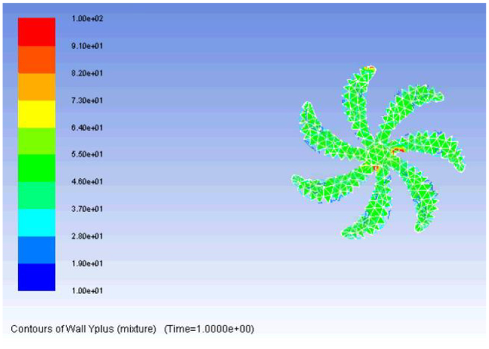
Contours of wall y+ on the propeller blade cells.
The computational domain is cylindrical and is generated similar to the validation model. A mesh study was made from coarse to fine mesh, respectively, with 0.6 to 1.648 million cells. The results are shown in Figure 5. The sound amplitude (SA) results from the fine mesh model are more stable than those from the coarse mesh and medium mesh models, but for all frequencies from 0 to 500 Hz, however, the SA results from coarse mesh and fine mesh cases are close; the results from medium mesh are lower than those from the coarse mesh and fine mesh cases. In the valuable analysis, the mesh is 1.648 million elements for the computation (Figure 3). In this study, for clear distinction, two kinds of models were used to apply and compare the consequences. The first model only has propellers and a duct to compare with submarine propellers without a duct. The second includes the submarine, propellers and input of different ducts to compute and compare with the basic model of a submarine.
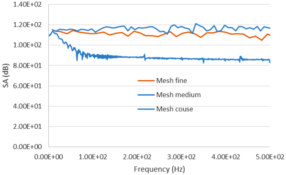
Comparison of the sound amplitude (SA) results from coarse to fine mesh.
Results and discussion
The diameter of the propeller and the submarine in this study is a scale model of a conventional propeller of E1619, and the submarine is the DARPA Suboff. The computation for the acoustic models using the LES method computation with different geometry cases is as follows: submarine and propeller (Case 1) and submarine and propeller with different geometries of ducts (six cases; Ducts 1–6). According to the outcomes of the various cases, we determine which shape of duct creates the most effective way to reduce the noise and thrust loss.
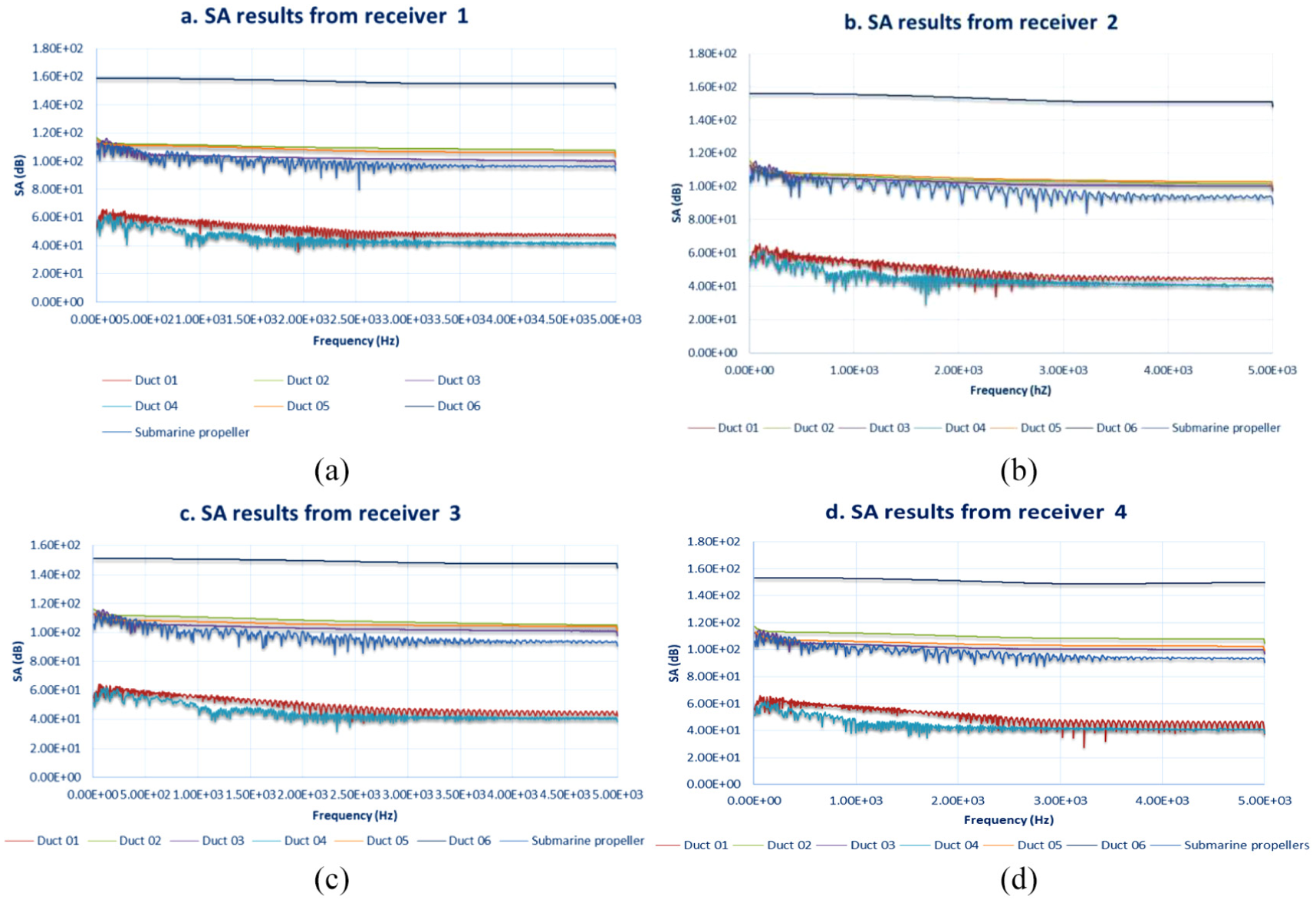
The SA results from the submarine propeller model without the submarine (Figure 6) with different receiver points show that different angles have different results because the noise directivity at each of the receiver points is different.4,18 In Figure 6(a), the SA results from Receiver 1 with Duct 1 are close to the submarine propeller results. For high frequency, the results from Duct 1 are a little lower than the model that only has propellers. In Receiver 2 (Figure 6(b)), the models for Ducts 4 and 2 show higher SA results. The other model has data similar to the submarine propeller that does not have a duct. At a high frequency (from 3 to 5 kHz), the results from Duct 3 are lower than the others. In Figure 6(c) and (d), the outcome is almost the same for different ducts. Only Duct 3 at a frequency of 4 to 5 kHz has lower results than the others including the submarine propeller with no duct.

Sound amplitude (SA) results from the receiver point of the propeller and duct model: SA result from (a) Receiver 1, (b) Receiver 2, (c) Receiver 3 and (d) Receiver 4.
The sound pressure level (SPL) outcome is shown in Figure 7 with different receiver points in different cases. In Figure 7(b)–(d), the outcomes with different models of the submarines are almost similar at low frequencies, and only the model with Duct 3 at a high frequency has lower SPL; Figure 7(a) is different. The result from Duct 1 is the lowest, followed by the model with no duct and the results from Ducts 2 and 6. The highest SPL outcomes are the results from Ducts 3–5 for all frequencies.

Sound pressure level (SPL) results from the receiver point of the propeller and duct model: SPL results from (a) Receiver 1, (b) Receiver 2, (c) Receiver 3 and (d) Receiver 4.
The outcome from the geometry model without the submarine shows that the model with Duct 1 has similar noise data or can be reduced a little, but this result did not show a clear distinction. Now, the results from all the produced submarine models are compared with the outcomes from the different ducts. Figure 8 shows that the SA outcome of Duct 6 is the highest. After that, the results of Ducts 2, 3 and 5 are similar to the model without a duct. Lower results are shown by Ducts 1 and 4. The results from the SPL (shown in Figure 9) are also not much different. The more reduced models are shown by Ducts 1 and 4, followed by the outcomes of models with Ducts 2, 3 and 5. The SPL is a little higher with the submarine propeller model. The last one with the highest SPL is Duct 6.
Sound amplitude (SA) results from the receiver point of the submarine, propeller and duct model: SA results from (a) Receiver 1, (b) Receiver 2, (c) Receiver 3 and (d) Receiver 4.

Sound pressure level (SPL) results from the receiver point of the submarine, propeller and duct model: SPL results from (a) Receiver 1, (b) Receiver 2, (c) Receiver 3 and (d) Receiver 4.
The outcome from Figure 10 is compared with the result of the submarine propellers without a duct, and the model with duct and propeller without a submarine is compared with the full submarine model. All of the results stay nearly in the middle. The model of the submarine propellers without a duct and the full model with Ducts 2, 3 and 5 have similar or a little higher results. The outcome of Duct 6 is the same, too high with the submarine propeller model. The model that can reduce more noise used Ducts 1 and 4.
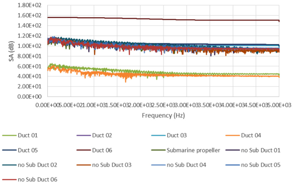
Comparison of the results of Receiver 2 with two kinds of models.
Figure 10 shows that the model with the submarine will change the flow of the liquid and then the pressure affects the propellers, changing the noise. To better understand this problem, Figure 11 compares the vorticity magnitude of the propellers of the original submarine model with the submarine model combined with a duct. Figure 11(a) shows the vorticity magnitude on propellers without a duct model. The vorticity magnitude focuses on the tip of the propellers that can increase the tip vortex, which increases the noise when the propeller is activated. With the model of the submarine combined with a duct (Figure 11(b)), the vorticity magnitude is stretched along the propeller blade, decreasing the tip vortex. This may decrease the noise on the submarine propeller model with Ducts 1 and 4.
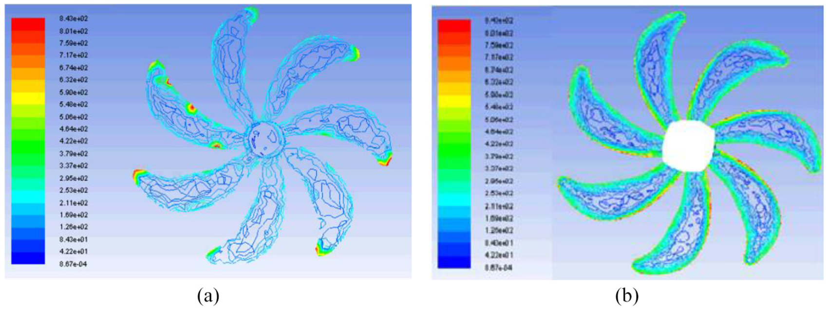
Vorticity magnitude on the propeller blades of the submarine model combined with Duct 1: (a) model without a duct and (b) model with a duct.
In Figures 10 and 11, it is clear that the submarine propellers with Ducts 1 and 4 are better models to reduce noise compared to the submarine propellers without a duct. The chart shows that the model with Duct 4 reduces the noise best, followed by Duct 1. The model with Duct 6 will increase noise than the submarine model without a duct. For Duct 3, the chart shows that, at a low frequency, it can reduce noise, but at a high frequency, this model increases noise.
Figure 12 illustrates the thrust force from the model case. All submarine model cases combined with a duct have a thrust force result that is higher than the model of the submarine that only has a propeller (531,900 N). The chart in Figure 12 shows that the thrust force from the model case combined with Duct 1 is the highest thrust force. This case increases the thrust force by 5.23%. Duct 6 can increases the thrust force by 4.87%. For the other models, the thrust force did not increase much. Duct 2 increased by 3.67%, Ducts 4 and 5 increased by 2.43% and Duct 3 increased only by 2.09%.

Thrust results on the propeller.
Finally, from both the noise and thrust standpoints, Duct 1 is the best because it can reduce the noise and increase the thrust force. Duct 6 can increase not only the thrust force, but also the noise outcome. Duct 4 can reduce noise, but the thrust force increase from this model is too small. Other ducts can increase the thrust force higher than the submarine propeller model without a duct, but they make the noise similar or slightly higher than the original submarine model. This is not effective for submarine work.
Conclusion
In this article, the acoustic model computational results using the LES method show good agreement with the experimental results of the DARPA Suboff AFF8. This indicates that the method used in this article is an effective tool for predicting the performance of a propeller. The noise measured by the SPL and SA at different locations and the thrust of the propeller showed that when the submarine appends a duct, it can reduce noise and increase thrust. This phenomenon is very good for a submarine. Of the six different duct shapes presented in this article, Duct 1 is the best model that can reduce noise and simultaneously increase thrust for submarines, followed by Duct 4, which slightly increases the thrust force but can reduce noise.
In future work, we will improve our study on the reasoning of the relationship between the duct shape and thrust.
Footnotes
Handling Editor: Yunn-Lin Hwang
Declaration of conflicting interests
The author(s) declared no potential conflicts of interest with respect to the research, authorship, and/or publication of this article.
Funding
The author(s) received no financial support for the research, authorship, and/or publication of this article.