
Abstract
The locally unsteady flow field near the orifice outlet of an aerostatic thrust bearing causes the gas pressure fluctuation on the bearing surface, which induces microvibration even if an invariable load acts on the bearing. In this article, flow field disturbance structure was designed for the air chamber of an aerostatic thrust bearing to change the microscopic flow field inside the bearing. Numerical calculation showed that flow field disturbance structure altered the gas flow characteristics in local flow field near the orifice outlet. Moreover, the fluctuating pressure on the bearing surface decreased obviously. Experiments demonstrated that the microvibration of the bearing with flow field disturbance structure was suppressed evidently. Furthermore, the influence of flow field disturbance structure parameters on the microvibration was analyzed experimentally.
Keywords
Introduction
The pressurized gas effuses from orifice and shoots to the bearing surface when an aerostatic thrust bearing works as a supportive element. At the orifice outlet, gas flow alters quickly as gas channel area increases suddenly and flow direction changes sharply. 1 The local flow field experiences complicated transformation (laminar flow transmits to turbulent flow and then in an inverse order) and many vortices even negative pressure (relative to the bearing outlet) emerges in the air chamber. 2 The unsteady flow causes rapid fluctuation of the pressure on the bearing surface and induces the bearing microvibration in frequency varying from several hertz to several thousand hertz and in amplitude of sub-micrometers. However, the gas film damping coefficient of the bearing is too small to attenuate the vibration energy immediately. Vibration isolation is less effective as the microvibration always occurs even if an inviable load acts on the bearing, whereas it may make the structure complicated and influence the static and dynamic performance of the bearing. In recent years, the mechanism and corresponding suppression methods for the microvibration of an aerostatic thrust bearing have gained wide attention.
Yoshimura et al. 3 reported that the sub-micrometers microvibration of an aerostatic thrust bearing was caused by the unsteady flow field near the bearing outlet. The Reynolds number near the bearing outlet was in correlation with the vibration amplitude and it should be reduced if an aerostatic thrust bearing was designed with high precision. Chen and colleagues4,5 reported that the vortex inside an aerostatic thrust bearing induced the microvibration. Using vortex strength (the maximum pressure difference between the vortex center and the edge) to forecast the microvibration amplitude, they found that an aerostatic thrust bearing with a spherical air chamber was more stable than the bearing with a rectangular air chamber or without an air chamber. Furthermore, they verified the conclusion experimentally. Aoyama et al.6,7 numerically analyzed the stability of the flow field inside an aerostatic thrust bearing with an inherent orifice-type restrictor. They reported that vortex strength could be reduced and the microvibration be suppressed by rounding the orifice outlet. Xu et al. 8 increased the gas film damping coefficient by adopting an air spring damping structure. Experiments showed that the microvibration energy was decayed quickly and the vibration amplitude was suppressed obviously. Using the maximum Mach number of gas velocity in the air film as the benchmark of bearing stability, Li et al. 9 reported an optimization method of designing aerostatic bearing with high stiffness and no microvibration.
In this article, flow field disturbance structure (FFDS) was designed for the air chamber of an aerostatic thrust bearing with a pocketed orifice-type restrictor to change the locally unsteady flow field near the orifice outlet and reduce the fluctuating pressure on the bearing surface. Numerical calculations and experiments demonstrated that FFDS had little effect on the load carrying capacity (LCC), stiffness, and mass flow rate (MFR) of the bearing. However, the microvibration was suppressed significantly. Compared with other microvibration suppression methods for an aerostatic thrust bearing, FFDS had the merits of simple structure, easy manufacture, and better suppression effect. The method might give a new way of designing an aerostatic thrust bearing with high precision and low microvibration.
This article is organized as follows: the next section gives the model of an aerostatic thrust bearing with FFDS, and a comparison of the flow characteristics is made between an aerostatic thrust bearing with a conventional structure and that with FFDS. The subsequent section verifies the effectiveness of FFDS on microvibration suppression. The section followed analyzes the influence of FFDS parameters on the microvibration. Conclusions are given in the last section.
Model of an aerostatic thrust bearing with FFDS and its flow field characteristics
Figure 1(a) shows the conventional structure of an aerostatic thrust bearing with a pocketed orifice-type restrictor—where d1 is the orifice diameter, D1 is the bearing diameter, D2 is the air chamber diameter, h1 is the film thickness, and h2 is the air chamber depth.

Aerostatic thrust bearing with a pocketed orifice-type restrictor: (a) bearing sketch and (b) grid and boundary condition of the model.
The gas channel area increases sharply from
The whole flow field inside the bearing is calculated. However, the flow characteristics near the orifice outlet is enlarged and displayed as it changes quickly and influences the microvibration of the bearing greatly. The pressure and velocity contours near the orifice outlet of an aerostatic thrust bearing with a pocketed orifice-type restrictor (d1 = 0.1 mm, D1 = 40 mm, D2 = 6 mm, h1 = 12 µm, h2 = 0.1 mm, and supply pressure is 0.5 MPa) are shown in Figure 2(a) and (b), respectively. The figures indicate that there are many vortices near the orifice outlet. The interaction between the pressurized gas and the bearing surface causes the boundary layer increase and makes the velocity distribution very complicated. The unsteady flow field induces the pressure (area-weighted average pressure (AWAP)) fluctuation on the bearing surface, as shown in Figure 2(c). The fluctuating pressure results in the microvibration of the bearing.

Flow characteristics and fluctuating pressure of a conventional bearing structure: (a) pressure contours, (b) velocity contours, and (c) fluctuating pressure on the bearing surface.
In order to change the unsteady flow field near the orifice outlet and make the bearing stable, FFDS (symbol A in Figure 3) is designed for the air chamber of an aerostatic thrust bearing with a pocketed orifice-type restrictor, where d2 and d3 are inner and outer diameter of FFDS, respectively, h3 is the height of FFDS, and the width of FFDS is

Aerostatic thrust bearing with FFDS.
The pressure and velocity contours of the bearing with FFDS are shown in Figure 4(a) and (b), respectively. The flow field near the orifice outlet is enlarged to analyze the influence of FFDS on the flow characteristics, where d2 = 3 mm, w = 0.2 mm, and h3 = 0.1 mm. The parameters of d1, D1, D2, h1, h2, and supply pressure are the same as those of the bearing with a conventional structure. It is concluded that the number of the vortex decrease noticeably after adding FFDS inside the bearing. Therefore, FFDS makes the flow field near the orifice outlet more stable than the bearing with a conventional structure.

Flow characteristics of the bearing with FFDS: (a) pressure contours and (b) velocity contours.
Figure 5 compares the fluctuating pressure on the bearing surface between the bearing with a conventional structure and that with FFDS. The maximum fluctuating pressure decreases from 396.4 to 167.1 Pa after adding FFDS in the air chamber. It is concluded that the fluctuating pressure is restrained significantly and the microvibration of the bearing can be suppressed. The reason is that the flow structure is disturbed and the vortices are suppressed by FFDS that make the fluctuating pressure on the bearing surface to be reduced.

Fluctuating pressure of the bearing with a conventional structure and that with FFDS.
Experiments
Aerostatic thrust bearings with a conventional structure and FFDS were designed and manufactured in order to verify that FFDS could suppress the microvibration of the bearing, as shown in Figure 6(a) and (b), respectively. The parameters of the bearing with a conventional structure were the same as those discussed in section “Model of an aerostatic thrust bearing with FFDS and its flow field characteristics.” The inner diameter of FFDS

Aerostatic thrust bearings for experiments: (a) bearing with conventional structure and (b) bearing with FFDS.
Experiments were carried out on the performance-testing device (as shown in Figure 7) as illustrated in our previous wok. 12 In the experiments, LCC of the bearing with different film thicknesses was first determined, as shown in Figure 7(b). The film thickness was measured by a displacement transducer (type GT2-H12K; Keyence Corporation) in the step. Then, an equal load generated by a set of weights especially designed and manufactured for the experiments was fastened to the bearing. The film thickness was equal to the corresponding film thickness attained in the previous step because the load was equal to LCC when the microvibration was not considered. It was difficult to measure the microvibration amplitude directly with high precision displacement sensor as the vibration was in sub-micrometers scale and with a broad bandwidth. Therefore, three acceleration sensors (type 352C42; PCB Corporation, axisymmetrically disposed) were fastened on the weight for vibration acceleration testing, as shown in Figure 7(c). The microvibration amplitude was calculated by double integral of the acceleration.

Experimental setup: (a) experimental setup sketch, (b) LCC measurement, and (c) vibration testing.
The acceleration signal might drift and deviate from base line because of the influence of unstable factors, such as environmental vibration. Direct integral of the acceleration signal would bring bigger errors. Therefore, polynomial least squares method was used to eliminate the mean deviation. Suppose the vibration signal obtained by experiments was

where m was polynomial order and sampling interval was Δt = 1/fs. fs was sampling frequency. The error squares sum between

The coefficient

m + 1 equations could be obtained by equation (4)
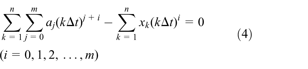
Resolved equation (4) and
In the Fourier transformation, the Fourier component of acceleration signal at frequency

where M was the coefficient of

where

Suppose the initial amplitude and velocity of the microvibration were zeros

The first integral formula in frequency domain was as follows

The second integral formula in frequency domain was as follows
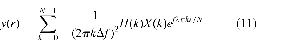
X(k) was the Fourier transformation of x(r).
where

fd and fu were the lower and upper cutoff frequencies, respectively.
Figure 8 shows the microvibration of the aerostatic thrust bearings with a conventional structure and that with FFDS. The maximum vibration amplitude decreases from 53.9 to 28.6 nm of the bearing with FFDS. The microvibration of the bearing is suppressed obviously.

Microvibration of the bearing with a conventional structure and that with FFDS.
Figure 9 illustrates LCC by LES calculation and experiments. The LCC is calculated by the mean pressure on the bearing surface. The figure shows that LES can predict LCC accurately.

LCC attained by LES and experiments.
Influence of FFDS parameters on the microvibration of the bearing
Tables 1 and 2 list the microvibrations of an aerostatic bearing with different supply pressures, FFDS parameters, and film thickness. It is concluded that FFDS suppresses the microvibration for the bearing with different supply pressures and film thicknesses. The microvibration of the bearing with FFDS increases with the growth of supply pressure and film thickness. Moreover, the position, width, and height of FFDS influence the microvibration evidently. By analyzing the relationship between FFDS parameters and the microvibration amplitude, one can find the following consequences:
The microvibration amplitude increases with the growth of FFDS inner diameter if other parameters are constant. The reason is that the unsteady flow field appears near the orifice outlet. The smaller the distance is away from the orifice outlet, the larger the turbulence strength is. Therefore, the smaller the inner diameter of FFDS is, the better effect of flow field disturbance is.
The microvibration of the bearing decreases with the growth of FFDS width if other parameters are constant. The larger the width of FFDS is, the closer the bearing is to an inherent orifice type (air chamber diameter D1 = 0). The bearing is more stable.
The microvibration of the bearing decreases with the increase in FFDS height if other parameters are constant. The larger is the height of FFDS, the better effect of the flow field disturbance is. The microvibration suppression is more effective.
Microvibration amplitude of the bearing with different FFDS parameters.

Microvibration amplitude of the bearing with FFDS for different film thicknesses.
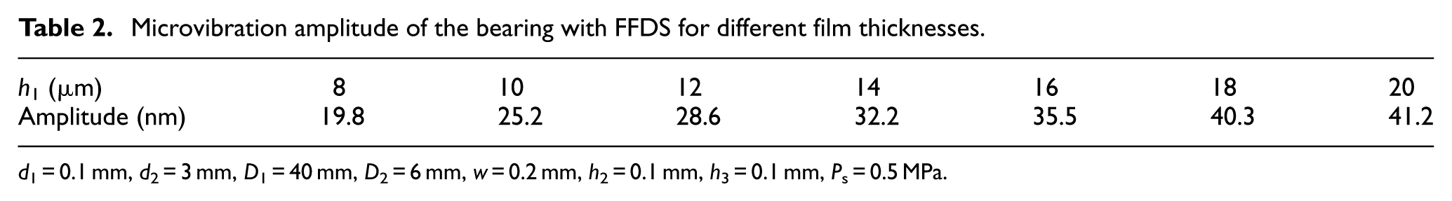
d1 = 0.1 mm, d2 = 3 mm, D1 = 40 mm, D2 = 6 mm, w = 0.2 mm, h2 = 0.1 mm, h3 = 0.1 mm, Ps = 0.5 MPa.
Conclusion
In this article, FFDS was designed for the air chamber to change the microscopic flow field near the orifice outlet of an aerostatic bearing with a pocketed orifice-type restrictor. Numerical calculation indicated that FFDS could restrain the fluctuating pressure on the bearing surface. Experiments demonstrated that the microvibration of the bearing was suppressed evidently. However, FFDS had little effect on LCC, stiffness, and MFR of the bearing. The microvibration of the bearing could be suppressed if FFDS was featured with small inner diameter, larger width, and big height. Compared with other microvibration suppression methods, FFDS had the merits of simple structure, easy manufacture, and better suppression effect.
The future work will focus on the systematical analysis of the influence of FFDS parameters on the microvibration so as to investigate the structure parameters’ optimization method for designing a low microvibration aerostatic thrust bearing by adopting FFDS.
Footnotes
Academic Editor: Jia-Jang Wu
Declaration of conflicting interests
The author(s) declared no potential conflicts of interest with respect to the research, authorship, and/or publication of this article.
Funding
The author(s) disclosed receipt of the following financial support for the research, authorship, and/or publication of this article: This study was sponsored by the National Nature & Science Foundation of China under grants 51275499 and 50905171, Nature & Science Foundation of Zhejiang Province, China under grant LY15E050014, and Research Project of State Key Laboratory of Mechanical System and Vibration MSV 201516.