
Abstract
In industrial applications, highly accurate mechanical components are generally required to produce advanced mechanical and mechatronic systems. In machining mechanical components, contour error represents the product shape quality directly, and therefore it must be considered in controller design. Although most existing contouring controllers are based on feedback control and estimated contour error, it is generally difficult to replace the feedback controller in commercial computerized numerical control machines. This article proposes an embedded iterative learning contouring controller by considering the linearly interpolated contour error compensation and Bézier reposition trajectory, which can be applied in computerized numerical control machines currently in use without any modification of their original feedback controllers. While the linearly interpolated contour error compensation enhances tracking performance by compensating the reference input with an actual value, the Bézier reposition trajectory enables smooth velocity transitions between discrete points in the reference trajectory. For performance analysis, the proposed controller was implemented in a commercial three-axis computerized numerical control machine and several experiments were conducted based on typical three-dimensional sharp-corner and half-circular trajectories. Experimental results showed that the proposed controller could reduce the maximum and mean contour errors by 45.11% and 54.48% on average, compared to embedded iterative learning contouring controller with estimated contour error. By comparing to embedded iterative learning contouring controller with linearly interpolated contour error compensation, the maximum and mean contour errors are reduced to 20.54% and 26.92%, respectively.
Keywords
Introduction
Highly accurate mechanical components with high-curvature surface are widely required in the fields of aerospace, energy, power, medical, and automobile, such as knee joints, 1 propellers, 2 impellers with small splitter blades,3–5 gears, 6 and ship structural components. 7 To produce such components, many engineers choose the computerized numerical control (CNC) machining process, which has advantages of high production efficiency, high machining precision, and stable product quality. Five-axis CNC machining further improves the flexibility, precision, and efficiency.8,9 Due to the above objective, two or more axes on these machines have to simultaneously move and their motions must be controlled accurately in order to produce precise machined parts. 10 Achieving high precision in machining highly depends on control performance of each individual feed drive axis. 11 Under independent drive axial control, load disturbance or performance variance of either axis causes contour error. 12 Efforts to reduce or eliminate contour errors have been made through either the design of advanced feedback controllers (FBCs) for each feed drive or modifying the reference axial positions. 10 This issue has attracted many researchers in the machine tool community because it is directly related to the product quality.
A cross-coupled control (CCC) system was proposed for biaxial manufacturing systems to improve the contour accuracy by coupling the individual axial errors. 13 A new structure of cross-coupling controller with a simpler design process for precise tracking in motion control was proposed, 14 which can be implemented easily on most motion systems via reprogramming the reference position command subroutine. Many cross-coupled methods enhanced the contouring performance by coupling axial errors under high feed rates such as adaptive feed rate and cross-coupled iterative learning control (CCILC).15–19 The CCILC improved the motion control performance by combining individual axial iterative learning control (ILC) and CCILC into a single control input. Applying the techniques of ILC to CCC enables learning of the cross-coupled error which leads to a modified control signal and subsequent improvements in the contour trajectory tracking performance. 19 However, there are three major limitations. The CCILC iteratively modified the control input signal which requires full access to the existing controller for redesigning or reprogramming, so it will be difficult to implement to commercial CNC machines in which access to the controller is generally not allowed. Second, the CCILC requires more iterations to reduce contour error in higher curvature trajectory because the simple contour error estimation does not provide sufficient estimation performance of the actual contour error. Third, commercial CNC machines generally equip already well-tuned FBCs, and hence they should be maintained in particular for machines currently in use.
In ILC, a machining error is reduced iteratively through modification of the control input or the reference trajectory. In linear-type ILCs, the convergence of the output error is guaranteed under a certain condition even when system parameters are not known exactly and periodic disturbances exist.20,21 Besides, ILCs with a contouring controller or an iterative contouring controller minimize the contour error through an iterative estimation of the instantaneous curvature of the reference trajectory and coordinate transformation. 22 Furthermore, the contour error can be significantly reduced by an ILC which considers both tracking and contour errors. 23 The contour error is approximated as the distance from the actual motion position to the tangential line of the desired contour. 13 The contour error for a biaxial free-form curve is estimated by approximating the desired curved path with a straight line that passed through the desired position, and the slope of the approximated line was determined by the average vector direction of the desired and the actual feed speed vectors.15,24 In addition, the contour error is estimated by calculating the deviation between the actual current position and the secant line of the desired path, and the secant line was obtained by passing through the command point of a certain time period before the current desired point. 25 Using circular approximation, the contour error estimation method is simplified by two-dimensional (2D) circular contours, which could be used for free-form curved paths. 26 A similar second-order method was also proposed by approximating the desired contour with an osculating circle. Then, the contour error is estimated by computing the distance from the actual position to the approximated circle. 27 Parameter-based contour error estimation algorithms were also proposed. However, the parameter equations of the desired tool path must be known, and the computational burden is also increased. 28 An embedded iterative learning contouring controller (EILCC) with contour error approximation by coordinate transformation was proposed in Hendrawan et al.,29,30 which could be applied to a commercial machine without any modification to the existing controller.
All of the methods mentioned above estimate 2D contour error and use approximated contour errors instead of the actual ones to design contouring controllers or modify reference trajectories.22,31,32 Most of the error approximation methods do not represent the contour error accurately, especially for a high-curvature surface application. However, contouring control with actual contour errors is difficult to be implemented in real-time control systems because the actual contour error cannot be obtained immediately for complex contour profiles. Therefore, it requires contour error estimation to obtain approximated values. On the contrary, with an embedded iterative control system, it is possible to obtain actual contour errors by offline calculation. However, this method generates nonuniform trajectory points along the reference path as explained in section “BRT,” which may produce nonsmooth velocity profiles. Therefore, the smoothing algorithm is needed to obtain smooth velocity profiles. Parametric splines, particularly Bézier curves (BCs), have been widely used for trajectory smoothing by interpolating linear trajectory points for both mobile robots and feed drive systems.33,34 Thus, they can be applied for the aforementioned scenario as well.
This study proposes an EILCC with linearly interpolated contour error compensation (LICEC) and Bézier reposition trajectory (BRT) to generate uniform trajectory points as shown in Figure 1. By calculating the minimum distance between the actual position and the reference trajectory, the LICEC is used to achieve the desired contour precisely 35 in the three-dimensional (3D) space. The EILCC modifies the original trajectory (NC program) with LICEC as an iterative learning controller. The modified reference trajectory is smoothed by quintic BCs through interpolation of the reference trajectory with uniformly distanced reference points to obtain a BRT. The BRT is executed by a CNC machine to reduce the contour error, iteratively. The proposed method is proven to provide better performance than the EILCC either with or without LICEC. The proposed method could be applied to commercial CNC machine tools without changing the existing controller. Generally, a commercial CNC machine has an existing well-tuned controller, which has good stability and disturbance rejection properties. The feedforward control is rather expected to improve the tracking performance by optimizing learning gain only with lower computational effort. The proposed method is suitable for mass production application because it may be desirable to provide dummy material in the beginning of the production to reduce the contour error in the EILCC. However, there is also a study on feed drive control, which mentions that feed drive motion accuracy mostly affects the precision of products because typical industrial machines have sufficient stiffness to the disturbance such as cutting force. Therefore, once the reference trajectory for the feed drive motion is optimized, it may still be effective for the finishing cutting process. 36 In typical heavy cutting cases, after rough cutting, finishing cutting is conducted. In that case, rough cutting does not need accuracy. Once the final reference trajectory is optimized by the proposed ILC in the air cutting process, the optimized trajectory can be applied for the finishing cutting process, which enables to produce high-precision products.

EILCC block diagram.
The rest of this article is organized as follows: section “EILCC with LICEC and BRT for three-axis CNC machine tools” gives a description of the dynamic model of three-axis machine tools, definition of the contour error, LICEC, BRT, controller design, and convergence analysis. Experimental results, which compare EILCC, EILCC with LICEC, and EILCC with LICEC and BRT in 3D sharp-corner and 3D half-circular trajectories, are presented in section “Experiment,” followed by concluding remarks in section “Conclusion.”
EILCC with LICEC and BRT for three-axis CNC machine tools
The dynamic model of three-axis machine tools
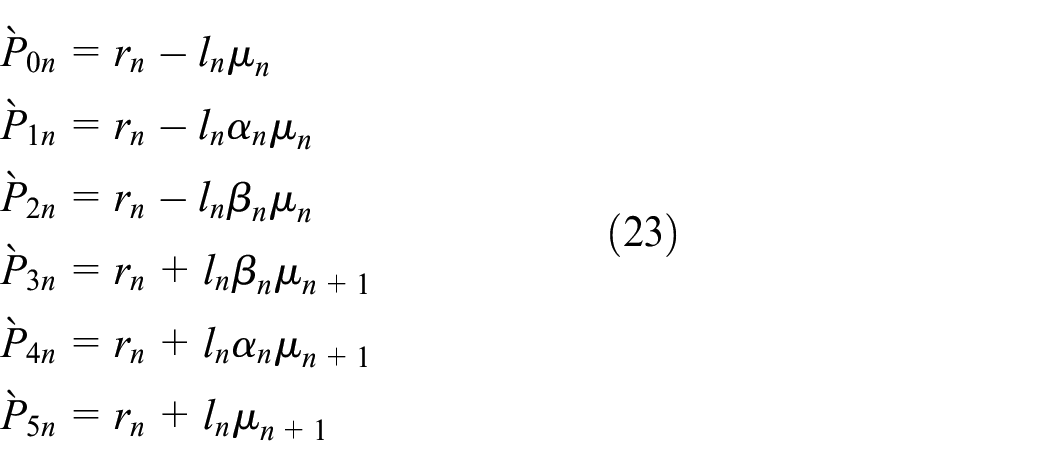
The dynamics of three-axis machine tools is represented as follows

where
Definition of contour error
The contour error is the error components orthogonal to the desired contour curves
37
or it can be defined as the shortest distance between the actual and desired contours. The difference between tracking error and contour error in machine tools is shown in Figure 2. The tracking error in each axis is the difference between the reference and actual positions. The reference position from the starting position of the machine tool system at time


3D tracking and contour errors. 35
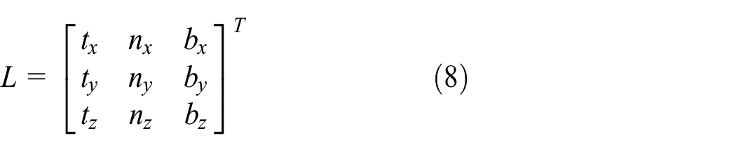
The coordinate frame

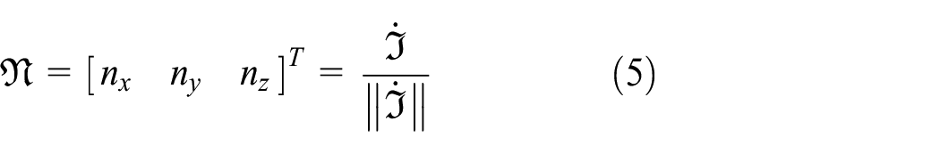

The tracking error vector

The closest position of the desired contour to


According to the contour error definition, it may define multiple closest positions and contour errors in a trajectory with an intersection part, for example, as shown in Figure 3 (

Sample trajectory with intersection part.
LICEC
LICEC is a direct method to compensate for the actual contour error by finding the closest position between the actual position and the reference trajectory as shown in Figure 2. Here we assume that the reference trajectory is represented by discrete points as

The shortest distance

where


where

In machining application, because the reference trajectory (G-code) consists of many discrete points which are connected by a linear short-line segment as shown in Figure 4, and hence linear interpolation is chosen for contour error estimation. The actual position


where

Contour error interpolation.
BRT
Herein, BRT refers to the modified reference trajectory that has been smoothed by quintic BCs through interpolation of the EILCC-modified reference trajectory with uniformly distanced discrete points as shown in Figure 5, where

Bézier reposition trajectory concept.
BC is a parametric curve defined by several control points depending on its order, and it always passes through the starting and ending control points.
33
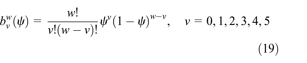
A BC of order
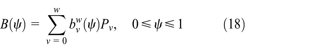
where
The BRT has two main parts: BC generation and reposition of the trajectory points. BC generation considers parameterization of a linear segment by a BC and corner smoothing by an inserted Bézier curve (IBC) as detailed in Simba et al. 34
From equations (18) and (19), the BC and the IBC with the fifth-order Bernstein polynomials for

and

where

and
where

From equations (21) and (23), the point

From equations (24) and (25), the length

Because

where
The generated BRT has a higher number of discrete points than the original reference trajectory, which directly affect the velocity profile. Therefore, the number of points is re-calculated based on the sampling time and the desired velocity as follows
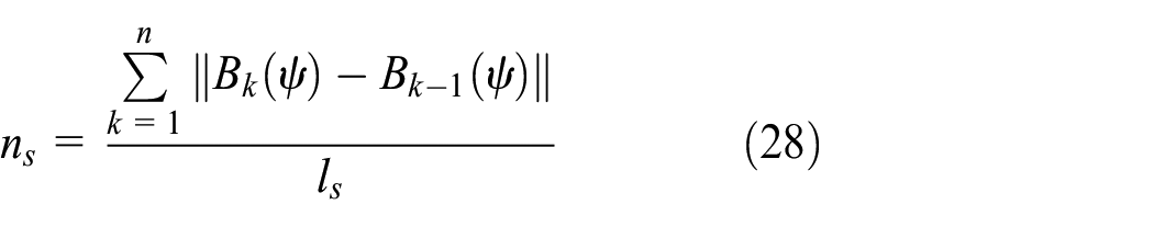

where

Controller design
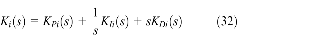
The proposed controller for the three-axis machine tool consists of an FBC and an EILCC with LICEC and BRT. The input of the FBC is the modified reference trajectory BRT generated from the ILC with LICEC as shown in Figure 6, where
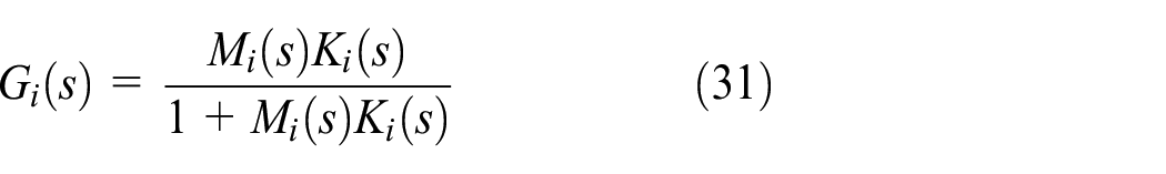
where
where

where

with

where

Substituting equation (34) into equation (33) leads to


The proposed controller design.
Convergence analysis
Performance of the EILCC with LICEC and BRT can be guaranteed through convergence analysis to ensure that the contour error is iteratively reduced. The convergence condition of ILC is represented as

where
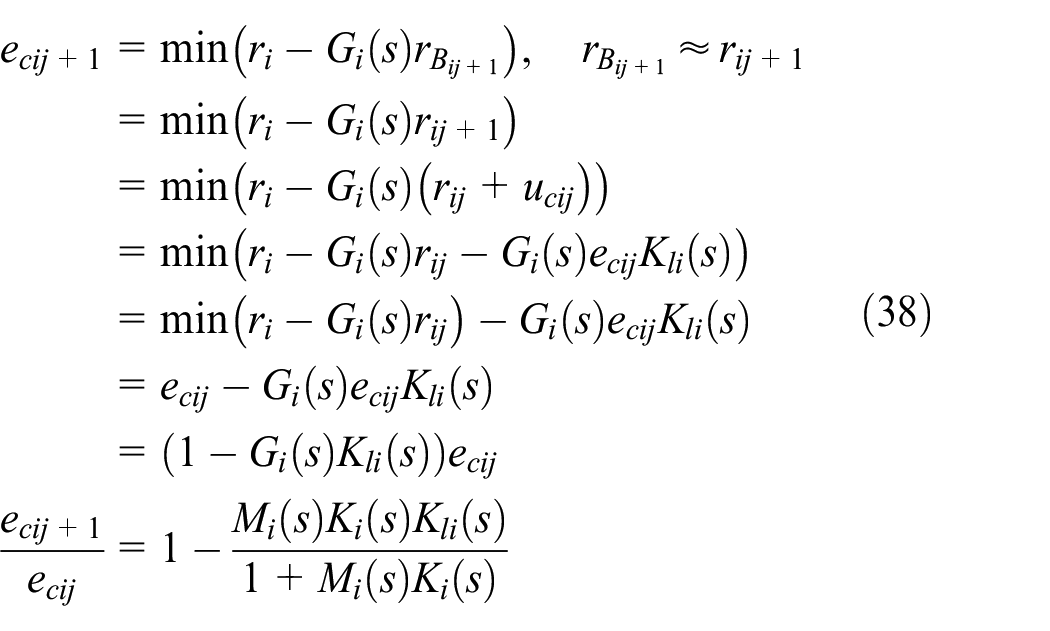
Substituting equation (38) into equation (37) leads to

Considering the discrete-time form for the implementation,
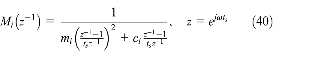
where


The convergence speed depends on the parameter
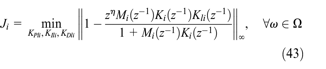
where
Experiment
Experimental configuration
A three-axis commercial CNC machine (Figure 7) with a ball screw mechanism, which is attached on a table and three servo motors. It is controlled by a Mitsubishi M70 controller which was used in the experiment to verify the effectiveness of the proposed controller. The actual position of the X–Y–Z table was measured by linear encoders with a resolution of

Three-axis CNC machine: (a) CNC machine and (b) table mechanism.
Plant and control parameters.


Experimental interface design.
The original FBC gain was originally assigned gains of the existing commercial CNC machine as
The following three types of controllers were considered for the experiment:
EILCC (with estimated contour error);
EILCC with LICEC;
EILCC with LICEC and BRT.
For each controller, two types of reference trajectories were executed, 3D sharp-corner trajectory and 3D half-circular trajectory, which were implemented in G-code form.
Experimental results for the 3D sharp-corner trajectory
The 3D sharp-corner trajectory consists of two linear segments, and sharp corners are generally difficult to be tracked by feed drive systems because of infinite acceleration due to a trajectory discontinuity at each corner. All of the drive axes move in the same direction before the sharp corner. After the sharp corner, the drive axis X continues with the same motion direction, whereas the drive axes Y and Z reverse their directions. This requires instant deceleration and acceleration in the drive axes Y and Z. If the typical PID control is used, an overshoot occurs at the corner.41,42 Because the proposed method can reduce contour error for the difficult trajectory such as a sharp-corner trajectory, it may work also for other shapes of trajectories properly.
The 3D sharp-corner trajectory is represented in G-code form as shown in Figure 9. For each controller, the five-time experiment was conducted until the minimum contour error was reached as shown in Figures 10–13. Figures 10(a), 11(a), and 12(a) and Figures 10(b), 11(b), and 12(b) show the trajectory tracking profiles for the 3D sharp-corner trajectory and the contour errors based on the EILCC, EILCC with LICEC, and EILCC with LICEC and BRT, respectively. In each case, results of the first iteration refer to the FBC only. Under EILCC, the initial largest contour error was

3D sharp-corner trajectory G-code. 35
Experimental results for the 3D sharp-corner trajectory by EILCC: (a) trajectory tracking profiles and (b) contour error.

Experimental results for the 3D sharp-corner trajectory by EILCC with LICEC: (a) trajectory tracking profiles and (b) contour error.

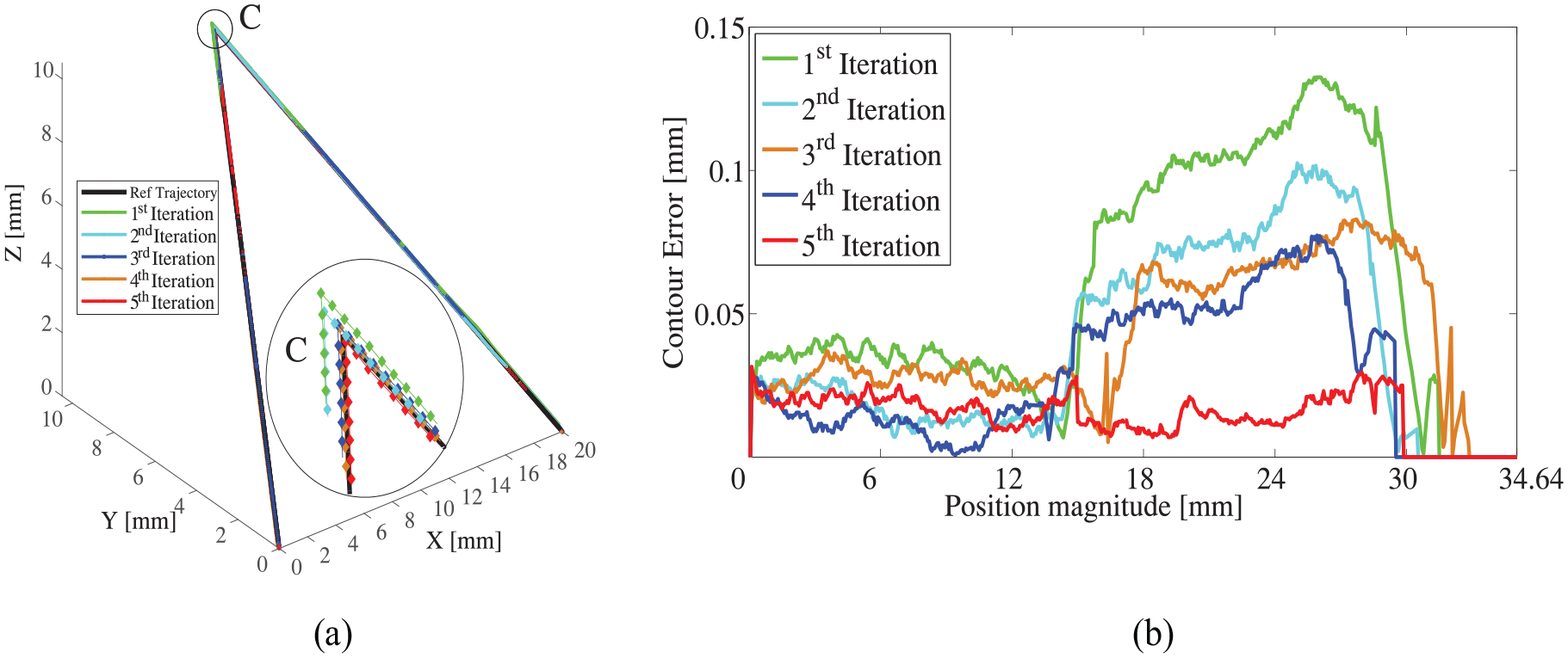
Experimental results for the 3D sharp-corner trajectory by EILCC with LICEC and BRT: (a) trajectory tracking profiles and (b) contour error.

Contour error experimental results for the 3D sharp-corner trajectory: (a) maximum contour error and (b) mean contour error.
Figure 13(a) and (b), respectively, shows the comparisons of the maximum and mean contour errors for the five-time experiments of the three controllers. It can be noted that the proposed controller, EILCC with LICEC and BRT, yielded the smallest values of the maximum and mean contour errors. Details of the experimental results are summarized in Table 2.
Summary of experimental results.
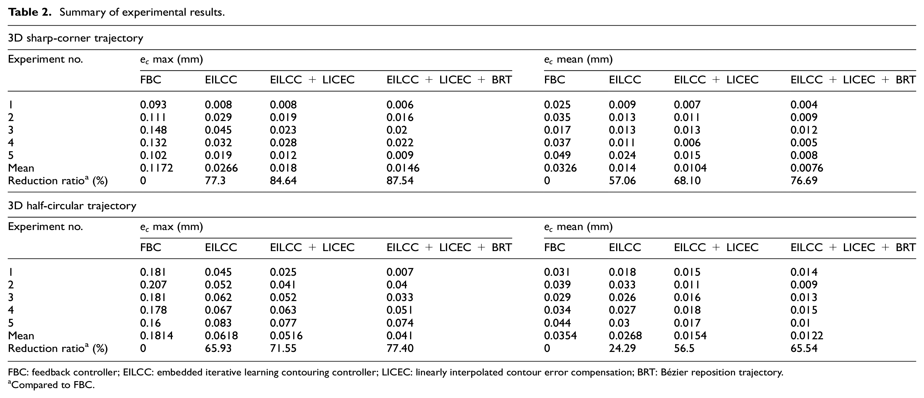
FBC: feedback controller; EILCC: embedded iterative learning contouring controller; LICEC: linearly interpolated contour error compensation; BRT: Bézier reposition trajectory.
Compared to FBC.
3D half-circular trajectory experimental results
The 3D half-circular trajectory in G-code form was generated by the following equation

Similar to the 3D sharp-corner trajectory, the five-time experiment was conducted for each controller until the minimum contour error was reached as shown in Figures 14–17. Figures 14(a), 15(a), and 16(a) show the trajectory tracking profiles, while Figures 14(b), 15(b), and 16(b) show the contour errors based on the EILCC, EILCC with LICEC, and EILCC with LICEC and BRT, respectively. Here also, the results of the first iteration refer to the FBC only. Under EILCC, the initial maximum contour error was
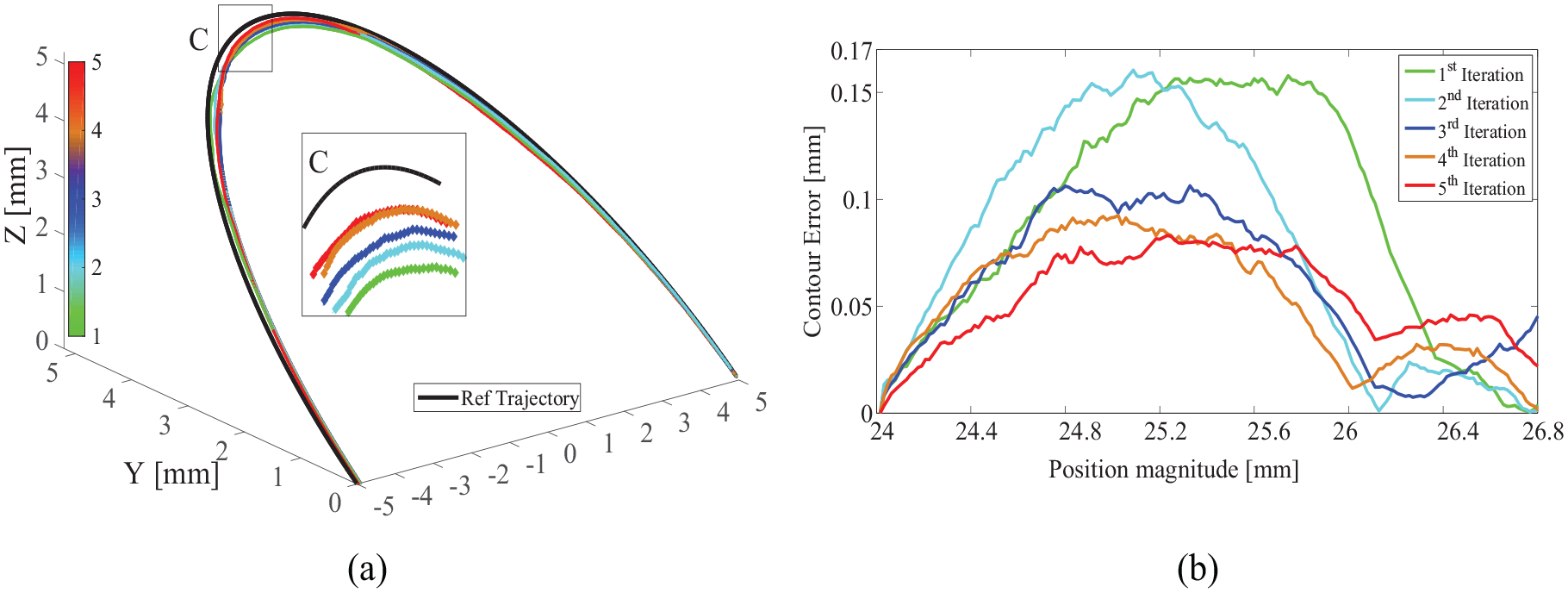
Experimental results for the 3D half-circular trajectory by EILCC: (a) trajectory tracking profiles and (b) contour error.
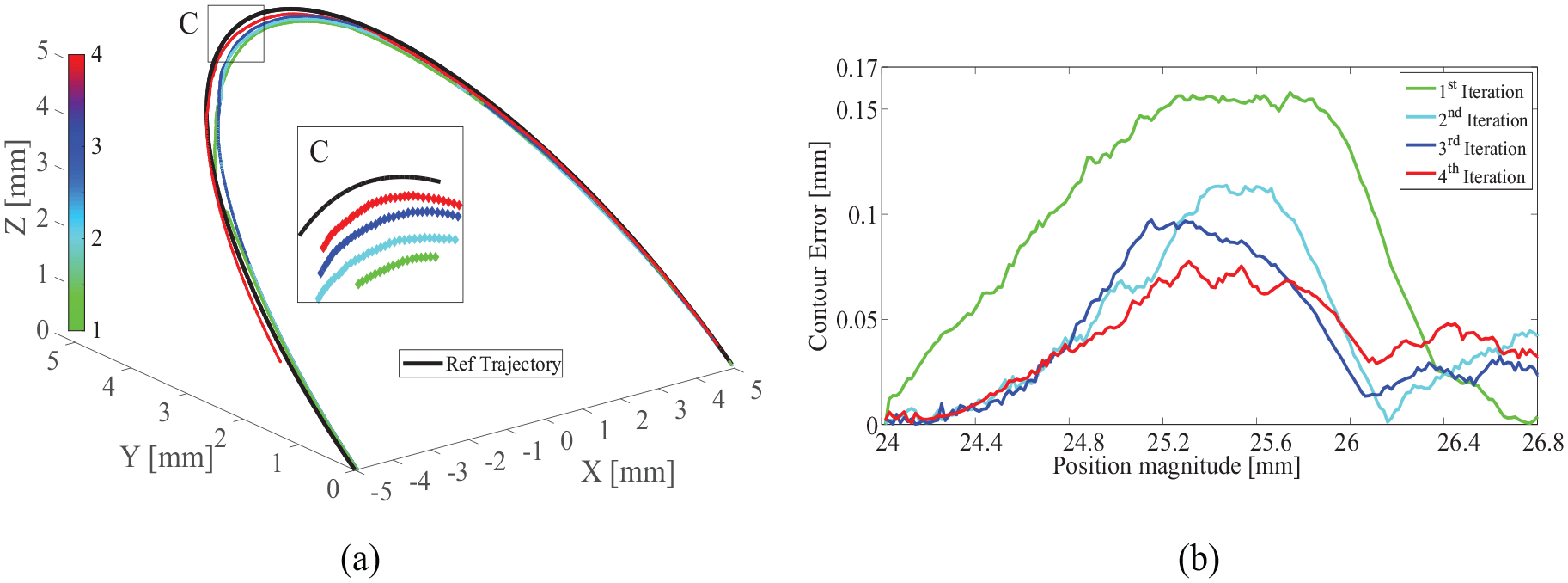
Experimental results for the 3D half-circular trajectory by EILCC with LICEC: (a) trajectory tracking profiles and (b) contour error.

Experimental results for the 3D half-circular trajectory by EILCC with LICEC and BRT: (a) trajectory tracking profiles and (b) contour error.
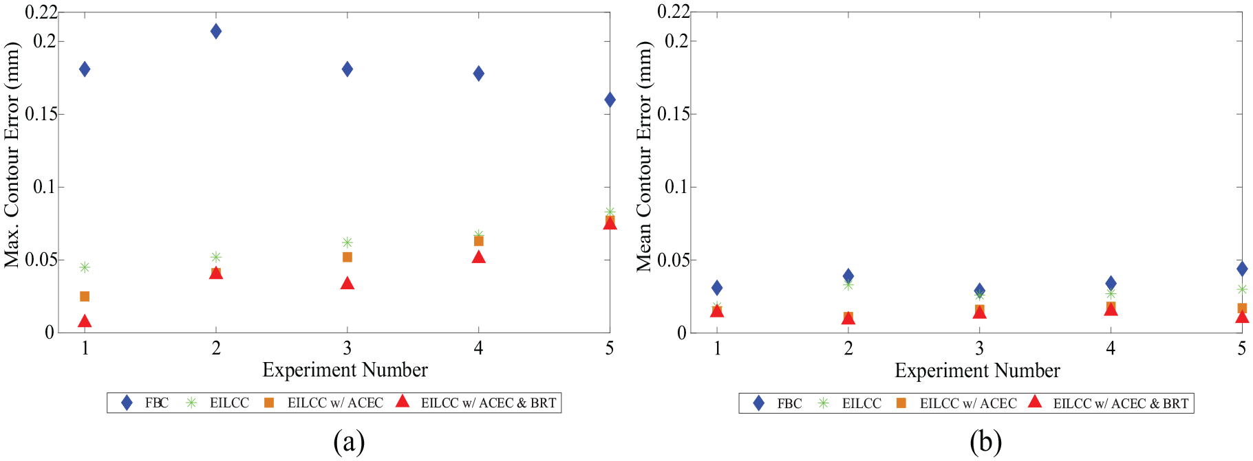
Contour error experimental results for the 3D half-circular trajectory: (a) maximum contour error and (b) mean contour error.
Comparison of the maximum and mean contour errors of the three controllers in the five-time experiments is shown in Figure 17(a) and (b), respectively. The average mean and maximum contour errors based on EILCC with actual contour error compensation (ACEC) and BRT were, respectively, reduced by
Conclusion
This study proposed a method to enhance the tracking performance of machine tool feed drive systems using EILCC with LICEC and BRT. The LICEC can estimate precise contour error for a higher curvature trajectory. Because the existing methods require access to the embedded controller for modifying the control input, it cannot be applied in commercial CNC machines. The proposed method is designed by a cascade scheme which enables it to be implemented in commercial CNC machines currently in use. An FBC of industrial machines is generally well tuned already. Although the ILC based on feedback control requires changing the well-tuned controller, the proposed approach is based on feedforward control, which is expected to improve the tracking performance, by iterative NC program modification. Its performance was verified experimentally with the 3D sharp-corner and half-circular trajectories in a commercial three-axis CNC machine. The experimental results of the proposed controller were compared to those of the traditional FBC and EILCC with estimated contour error, where the proposed controller achieved that the maximum and mean contour errors were reduced by 45.11% and 54.48% and 20.54% and 26.92% on average compared to EILCC with approximated contour error and EILCC with LICEC, respectively.
In the future, the EILCC could be extended to reduce energy consumption by energy analysis as well as convergence because industrial CNC machines consume a lot of energy. Furthermore, because the machining process is nonlinear, the EILCC performance can be improved by considering this non-linearity in the convergence analysis.
Footnotes
Handling Editor: James Baldwin
Declaration of conflicting interests
The author(s) declared no potential conflicts of interest with respect to the research, authorship, and/or publication of this article.
Funding
The author(s) disclosed receipt of the following financial support for the research, authorship, and/or publication of this article: This work was supported by the Ministry of Research, Technology and Higher Education of the Republic of Indonesia, which we would like to thank.