
Abstract
Unmanned aerial vehicles may collide with obstacles, such as trees or other unmanned aerial vehicles, while flying. A waypoint-based flight path is an approach to avoid such obstacles. To specify waypoints for the safe flight of unmanned aerial vehicles, it is necessary to define a flight path in advance by analyzing the flight records of unmanned aerial vehicles and thereby designate the waypoints automatically. However, there is a problem in that pilots tend to make errors in controlling unmanned aerial vehicles and collecting flight records. This article proposes a method to generate candidate waypoints for a flight path by removing such unintended flight records. In this method, images representing the positions in the collected flight records are generated. The candidate waypoints are generated as positions corresponding to the overlapping pixels of the images generated via image accumulation based on the flight records and the ones generated by accumulating the images reconstructed using an Autoencoder. The unmanned aerial vehicles can be set the waypoints for an autonomous flight using the candidate waypoints. An experiment was conducted in a university to generate candidate waypoints for road monitoring. The results obtained using the proposed method and K-means algorithm were compared. The candidate waypoints generated using the proposed method were reduced by 84.21% compared to those generated using the K-means algorithm.
Keywords
Introduction
Unmanned aerial vehicles (UAVs) 1 autonomously fly using onboard cameras and perform monitoring functions such as traffic regulation using onboard cameras.2–5 A pilot can control each UAV by watching UAV camera screens and considering UAV positions.6,7 However, it is difficult for a single pilot to control UAVs concurrently. Even if many pilots control different UAVs, it is difficult to predict the multiple flight paths of UAVs flown by other pilots. In the absence of a pilot, the UAV needs to autonomously determine its flight situation for an autonomous flight.
To recognize the flight situations of a UAV and to control it autonomously, the flight situations of UAV should be determined based on its surrounding and the values of the sensors installed onboard. An autonomous flight can be realized using a control method based on the flight situation.8–12 In the deep-learning phase of this method, a control signal is inferred from the images taken by a UAV, which shows its situation. The UAV can then be controlled based on the inferred control signal. The control signals required to fly to the desired targets are generated using the images captured by the UAV, which can then fly to the target following this signal. However, there is a problem in that it is difficult for a pilot to determine the flight path of UAVs from the positions of the UAVs.
Considering the flight environments, a pilot can define the waypoints where the multi-UAVs should fly in advance, and the UAVs will fly to those waypoints.13,14 However, the pilot must precisely determine these waypoints considering possible problems such as obstacles or collisions with other UAVs. If the flight plan is changed, the pilot needs to specify the waypoints once again.
The flight path for a UAV can be generated from its flight records.15–17 The candidate waypoints are generated by analyzing the flight records. The waypoints of the multi-UAVs are planned, and the UAVs can fly to the waypoints. However, any errors made by pilots in flight are reflected in the flight records, and if these records are used for generating the candidate waypoints, there will be a problem. Therefore, it is necessary to remove such unintended positions due to pilot error from the generated flight records. In the process of generating candidate waypoints for surveillance, it is necessary to increase the number of candidate waypoints in the area where surveillance is performed by removing unintended flight records.
This article proposes a method of generating candidate waypoints for UAVs, wherein the unintended flight data due to pilot error are removed using Autoencoder. Autoencoder 18 learns to reconstruct the images generated based on the flight records. The maximum and minimum positions of the flight records and the error range of the sensor in measuring these positions are used to set the size of the images. Based on the maximum position, minimum position, and error range of the sensor in measuring the position, images representing the positions included in the flight record are generated. The candidate waypoints are generated as an average of the positions of the overlapping pixels by comparing the images, which are combined with the images generated based on the flight records, with the images combined with the reconstructed images using the Autoencoder.
Thus, it is possible to specify the waypoints for UAVs based on the flight paths without reflecting any unintended flight records due to pilot error. Moreover, the flight path of UAVs or multi-UAVs can be planned by providing detailed waypoints using only the candidate waypoints for which surveillance is required.
The rest of this article is organized as follows. Section “Related works” describes the related works. Section “Autoencoder-based candidate waypoint generation method using images representing flight records” details a candidate waypoints generation method for an autonomous flight using the Autoencoder. Section “Experiments” describes experiments conducted in a university to generate candidate waypoints for road monitoring. Finally, section “Conclusion” presents the conclusions drawn from this study.
Related works
This section describes a method for controlling UAVs based on the flight records. Moreover, a method for analyzing the flight records and generating a flight path is introduced.
UAV control based on flight records
A pilot controls a UAV by recording the collected images and control signals during the flight. A convolutional neural network (CNN) is trained via the end-to-end method to control the UAV. 11 The CNN is learned to infer the control signal based on the input images. The UAV can then fly autonomously based on the inferred control signal learned from the CNN, which is trained by inputting the images taken by the UAV. Thus, the UAV flies autonomously in a manner similar to how a pilot would have flown it. However, as the optimal control signal corresponding to the current image is tracked, a method to infer the control signal considering the subsequent images is needed.
A deep-Q-network (DQN) is applied to infer the control signal based on the current and subsequent images. 19 The optimal control signal is deduced considering the subsequent images by learning the DQN. Active learning is implemented to check whether the learning is insufficient, determine whether the learning is good, and reinforce the learning about the lack of learning.
In the case of autonomous flight based on deep learning, a pilot can fly the UAV in the desired direction; however, the pilot cannot fly the UAV following the flight path set. There is a problem in that the same control signal cannot be deduced when there is a difference between the images taken by the UAV even in the same environment.
Generation of UAV flight path based on flight records
During the flight of a UAV, the images taken from the onboard camera are recorded, and a flight path is created. 17 The pilot controls and records the images taken from the UAV camera. The UAV is made to fly to a specific location shown in the photographed image and thereafter to another location shown in the subsequent recorded image. However, if the collected images and the flying environment change, the flight records must be collected again in the flying environment.
During flight, the UAV is controlled via the UAV location as analyzed from the captured images. The position of the UAV and the flight control method to be performed at this position can be determined using the images captured through the onboard camera. 19 Flight controls, such as moving left, right, or forward, are learned based on the collected images. As mentioned previously, the UAV determines the flight control method at the current position using the images taken from the camera. However, as the range of UAV flight increases, similar images may appear. This makes it difficult to control the flight, because of the similarity in the images taken at different locations.
While the pilot controls the UAV, it collects flight records based on the measured positions by the UAV.15,16 The UAV analyzes the collected flight records to generate locations for an autonomous flight. To analyze the flight records, the UAV positions are classified based on the K-means algorithm to generate the flight locations, which are then combined to create a flight path. The UAV flies along the generated flight path to the target location set by the pilot. The flight path of the UAV is provided by planning the positions to which to fly using the A* algorithm based on the generated flight path.
Any error made by the pilot during flight is reflected in the collected flight record, and if this flight record is used, the pilot may repeatedly execute the unintended flight record. Hence, a method is developed for pilots to remove the unintended flight record.
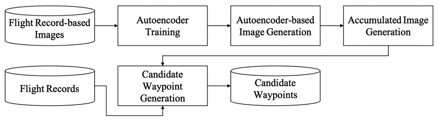
Autoencoder-based candidate waypoint generation method using images representing flight records
This section describes the process of generating candidate waypoints based on flight records. Accordingly, a method to generate candidate waypoints based on the collected flight records is introduced. Moreover, a method for obtaining images from the flight record and generating candidate waypoints using Autoencoder is described.
Overview
Figure 1 shows the process of generating the candidate waypoints using the Autoencoder. First, in the flight record collection stage, UAV flight records are collected to generate candidate waypoints. Second, in the flight record-based image generation stage, images are generated using the collected flight records. Third, in the Autoencoder-based candidate waypoint generation stage, candidate waypoints are generated using the Autoencoder.

The processes involved in the Autoencoder-based candidate waypoint generation method based on flight records.
Flight record collection
The pilot collects the positions of the UAV by controlling the UAV in the environment to generate the candidate waypoints.
15
The positions that the pilots collect during the jth piloting of the UAV are defined as path record

UAV flight record collected by pilot control: (a) flight record P1, (b) flight record P2, and (c) flight record Pj.
Flight record-based image generation
An image is generated by inputting the value to the pixel corresponding to the positions included in the flight record so that it can be inputted to the Autoencoder. The error range of the sensor measuring the position of the UAV is defined as the position error range α. The minimum position in the measured flight records is defined as minimum position
The number of pixels in the image is defined as section
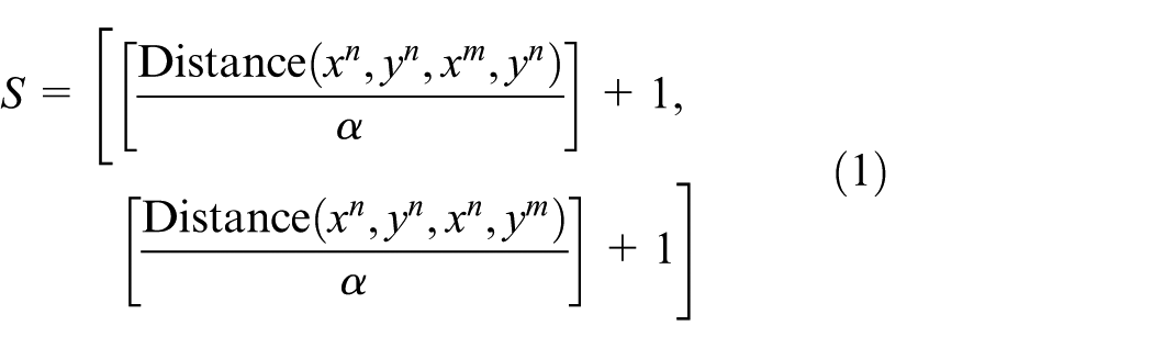
The image generated based on the jth corresponding flight record

If there is a pixel corresponding to a position in the flight record, it is either set to one or to zero. Figure 3 shows the record images generated using the positions in the flight record shown in Figure 2.

Record images generated using the positions in the flight records: (a) record image I1, (b) record image I2, and (c) record image Ij.
Autoencoder-based candidate waypoint generation
The Autoencoder-based candidate waypoint generation stage generates candidate waypoints through the processes shown in Figure 4. Autoencoder is trained using flight record-based images. The flight record-based images are reconstructed using the trained Autoencoder. The flight record-based images and Autoencoder-based reconstructed images are then accumulated. The candidate waypoints are generated from the results of the comparison of the accumulated images and the positions included in the flight records.
The processes of Autoencoder-based candidate waypoint generation.
In the Autoencoder training step, the Autoencoder learns to reconstruct the images by inputting the record images generated based on the flight records. Figure 5 shows the structure of the Autoencoder. The Autoencoder is learned by inputting the record images to the encoder and outputting the result from the decoder. The output of the Autoencoder, which is learned using the record images, is defined as the reconstructed record image

Structure of the Autoencoder.
In the Autoencoder-based image generation step, the flight record-based images are reconstructed using the trained Autoencoder. The result outputted from the decoder is defined as reconstruction probability β. The pixels of the reconstructed record image

Reconstructed record images obtained through trained Autoencoder: (a) reconstructed record image
In the accumulated image generation step, the accumulated images are generated by accumulating the record images and the ones reconstructed using the learned Autoencoder. The accumulated image

The reconstructed accumulated image

Results of (a) accumulated image
In the candidate waypoint generation step, candidate waypoints are generated using the accumulated image

Images containing: (a) duplicated pixels and (b) generated candidate waypoints.
Experiments
The process of generating candidate waypoints to monitor roads was tested in Dongguk university. The process and results of generating the images based on the flight records and obtaining the candidate waypoints based on the generated images are described in this section.
Collected flight records
Six flight records were collected by the university to monitor the roads. The flight records were collected using DJI Inspire. 20 Figure 9 shows the positions of the UAV in the six flight records, measured using the Global Positioning System (GPS).

Flight records collected using UAV-mounted GPS.
Image results expressed using positions of flight records
The record images were generated using the positions in the flight records. As the position error range of the GPS is ±2.5 m, the position error range α was set to 5. The minimum position

Generated flight record images: (a) record image I1, (b) record image I2, (c) record image I3, (d) record image I4, (e) record image I5, and (e) record image I6.
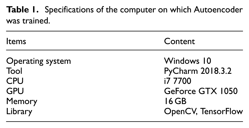
Autoencoder model and learning result
Figure 11 shows the structure of the Autoencoder model comprising two hidden layers. In the encoder, 5199 features of the input layer were reduced to 1289 in the first layer. In the second hidden layer, 1289 hidden features were reduced to 322 hidden features. The encoder was used to reduce the previous input by approximately 1/4th. The decoder was used to change the hidden feature from 322 to 1289 and 5159 layer-by-layer. The layer was configured to enlarge as much as the encoder. The learning rate was set to 0.01, and 100,000 learning tasks were performed.

Autoencoder model.
Autoencoder was trained using the computer specifications listed in Table 1. Figure 12 shows the change in the generated loss during the training of Autoencoder with the record images as input. The initial loss was 0.477, and the loss converges at 0.1.
Specifications of the computer on which Autoencoder was trained.

Change in the loss during Autoencoder training.
The reconstruction probability β was set to 0.8 to construct the reconstructed record image

(a) Accumulated image
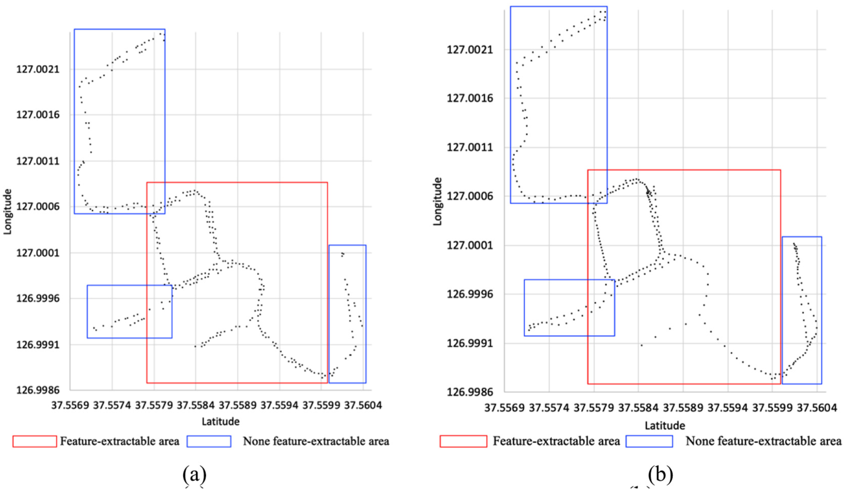
Figure 14 shows the composed images obtained using the overlapped pixels of accumulated images and reconstructed accumulated images by the proposed method when different learning data were used. In feature-extractable areas, the overlapped pixels have been reconstructed. The overlapped pixels were disappeared where there were none feature-extractable areas. In the case of the first flight record, although the entire flight record was reconstructed at first, as the training data accumulated, some of the initial flight records could not be reconstructed.

Results based on the amount of learning data: (a) overlapped pixels of accumulated image I1 and reconstructed accumulated image I’1, (b) overlapped pixels of accumulated image I2 and reconstructed accumulated image I’2, (c) overlapped pixels of accumulated image I3 and reconstructed accumulated image I’3, (d) overlapped pixels of accumulated image I4 and reconstructed accumulated image I’4, (e) overlapped pixels of accumulated image I5 and reconstructed accumulated image I’5, and (e) overlapped pixels of accumulated image I6 and reconstructed accumulated image I’6.
Analysis results of candidate waypoint generation
Figure 15 shows the results of candidate waypoint generation obtained through the proposed method. The proposed method helps generate 305 candidate waypoints using 17,351 collected positions. To compare the proposed method with the K-means algorithm, 15 K was set to 305 to generate candidate waypoints. With the proposed method, the more frequent the UAVs fly as per a flight record, the greater is the number of generated candidate waypoints, whereas the candidate waypoints generated using the K-means algorithm are relatively constant. In the case of feature-extractable areas, the candidate waypoints generated using the proposed method were densely located and were fewer than the ones generated using the K-means algorithm in none feature-extractable areas. The proposed method generates more accurate candidate waypoints in feature-extractable areas than the K-means algorithm. In none feature-extractable areas, the candidate waypoints could be removed.
Candidate waypoints obtained using (a) proposed method and (b) K-means algorithm.
Table 2 lists the results of accumulating the GPS distance differences between the collected flight records and the candidate waypoints based on the proposed method and K-means algorithm. The GPS distance differences between the collected flight records and the closest candidate waypoints are accumulated. In the case of feature-extractable areas, the GPS distance differences between the flight record and the candidate waypoints generated using the proposed method were reduced, whereas they increased in the case of none feature-extractable areas. As the candidate waypoints generated using the K-means algorithm were the average of the positions contained in the flight records, the GPS distance differences between the flight records and the candidate waypoints were determined uniformly. In the case of feature-extractable area, such as flight records
Accumulation of GPS distances between flight records and generated candidate waypoints.
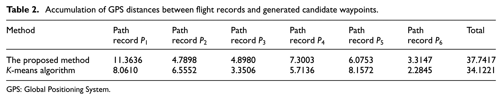
GPS: Global Positioning System.
Conclusion
This article proposed a method to generate candidate waypoints based on flight records. To generate the candidate waypoints, the collected flight records were generated as images, which were then inputted to an Autoencoder. The Autoencoder learned to reconstruct the input images. The candidate waypoints were generated by overlapping the reconstructed images with the images generated based on the flight records. The candidate waypoints could be combined to obtain a flight path. The flight path was obtained by planning the flight path to the candidate waypoints for performing surveillance using the generated flight path.
An experiment was conducted in a university to generate candidate waypoints for road monitoring. In the experiment, 17,351 positions were collected from six flight records. An image was then constructed using the six collected flight records, and 100,000 images were reconstructed by training Autoencoder. A total of 305 candidate waypoints were generated using the reconstructed images and the Autoencoder. The results of accumulating the distance between the candidate waypoints obtained using the proposed method andK-means algorithm were found to be 1.23 and 1.45 km, respectively. The difference between them was reduced.
Future research will be conducted on obtaining three-dimensional locations of candidate waypoints. Moreover, a method will be developed to plan a flight path for UAVs using candidate waypoints, including information, such as the expected battery cost, during the flight process.
Footnotes
Handling Editor: Yaoming Zhou
Declaration of conflicting interests
The author(s) declared no potential conflicts of interest with respect to the research, authorship, and/or publication of this article.
Funding
The author(s) disclosed receipt of the following financial support for the research, authorship, and/or publication of this article: This research was supported by Basic Science Research Program through the National Research Foundation of Korea (NRF) funded by the Ministry of Education (2018R1D1A1B07049990).