
Abstract
Analyzing of nonlinear carrying performance of hydrostatic ram is among key research questions to improve heavy machine tools because the machining precision will be directly influenced by it. A dynamic model of nonlinear supporting characters for hydrostatic ram is developed in this work. Modified Reynolds equation is resolved by finite difference method numerically to determine the carrying capability. Dynamic equilibrium equation of hydrostatic ram under cutting force impact is solved by Runge–Kutta method to obtain the variation of tool tip position and evaluate the machining accuracy. An optimal oil supply rate allocation and oil pad size is proposed to improve the static and dynamic performance simultaneously based on method of bisection.
Introduction
Hydrostatic ram is widely used in heavy machine tools because of its advantages as high stiffness, low wear, and vibration isolation. Pressurized oil flow is pumped into the oil pad by proportioning supply system. The hydrostatic effect caused by oil flowing through the oil seal edge maintains the pressure in oil pads which is prerequisite of carrying ability. The supporting performance of hydrostatic ram is essential to the optimization of machining accuracy because spindle handle is directly fixed on it.
Analyses of hydrostatic is usually conducted by resolving the Reynolds equation, which is a partial differential equation (PDE). A modified Reynolds equation describing incompressible oil flow is presented in N Wang et al.’s 1 research. Z Liu et al. 2 proposed a general Reynolds equation for rectangle oil pad of hydrostatic ram in a manufacturing model. The variation of oil viscosity and temperature can be ignored between slowly moving surfaces according to researches of M El Khlifi, 3 Liu et al., 4 and Wang et al. 5 In the study of Q Yang et al., 6 Wang et al., 7 and Masjedi and Khonsari, 8 non-Newtonian feature of oil can be neglect when maximum pressure is lower than 3 MPa. R Nicoletti, 9 Liu et al., 10 and Wang et al. 11 used numerical method to solve the Reynolds equation efficiently in their analyses. Finite difference method (FDM) is proved to be a practical and reliable method to resolve the Reynolds equation by J Li and others.12–15 study. Based on DA Bompos and Nikolakopoulos’s 16 calculation, most hydrostatic bearings are nonlinear over damping systems and periodic cutting will influence the displacement of machining point. The approximate cycle and amplitude of cutting force on heavy machine tools is determined by N Grossi et al. 17 and Tian et al. 18 measurement and computing. Equilibrium equation for analyzing dynamic performance is ordinary differential equation (ODE), which is solved numerically by Runge–Kutta method (RKM) in J Niu et al.’s 19 research. Based on the theory of multi-body system in Q Cheng and colleagues’20,21 article, the offset of tool tip position is influenced by all error component of machine tool, but improvement of one part is able to reduce the displacement. An evaluation method is applied by M Cha and Glavatskih 22 to analyze the carrying performance according to the offset of tool tip position under dynamic cutting force impact. Meng et al. 23 studied the oil supply rate influence on carrying capacity in his work which shows the pump rate is a practical way to optimize the performance of hydrostatic bearings. Changing the size of oil pad is considered as another optimal solution to improve the supporting ability in C Weißbacher et al.’s 24 and Cai et al.’s 25 studies.
A dynamic equilibrium equation of typical heavy machine tool is established to analyze the carrying performance of hydrostatic ram. Modified Reynolds equation is solved by FDM and equilibrium equation is resolved by RKM in order to determine the displacement of tool tip under dynamic cutting force impact. By evaluating the offset of machining point, optimal oil supply rate and oil pad length is obtained by method of bisection to improve the machining precision.
Hydrostatic ram modeling and numerical resolution
Modeling hydrostatic ram under cutting force impact
In heavy machine tools, the shaft at tip point is carried by hydrostatic ram which is the spot of butting force. The hydrostatic ram is usually fixed on the slide carriage and surrounded by oil pads in heavy machine tools, as shown in Figure 1(a). Rectangular oil pads shown in Figure 1(b) is suitable for linear movement like hydrostatic ram.

Model of hydrostatic ram: (a) Hydrostatic ram on slide carriage; (b) oil pad of hydrostatic ram.
In Figure 1(b), L is the length of the oil pad, B is the width of the oil pad, l is the length of the oil pocket, b is the width of oil the pocket, and H is the film thickness. In this model, the oil pore diameter is 0.015 m and the oil pad thickness is 0.02 m. The oil pad is fixed face-to-face to another oil pad to provide preload for each other on hydrostatic ram. Influenced by cutting force, the offset of hydrostatic ram includes sliding component rotating component, as shown in Figure 2.
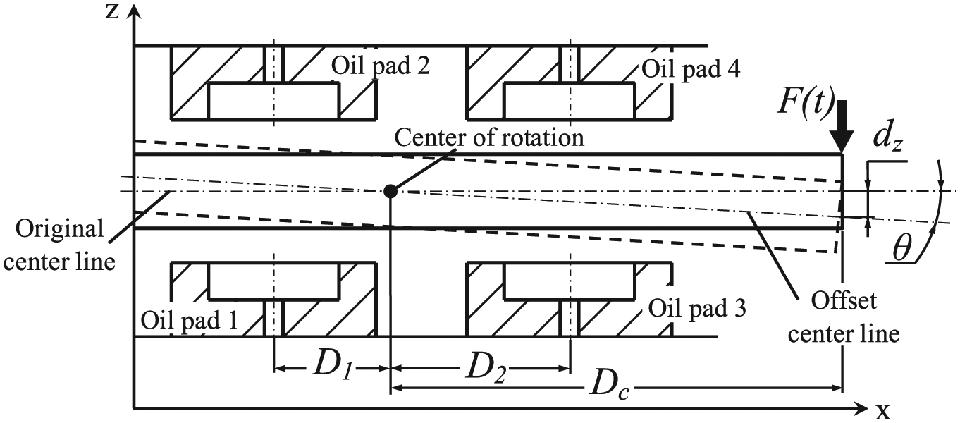
Displacement of ram under cutting force impact.
In Figure 2, oil pads 1 and 2 are fixed symmetrically as well as oil pads 3 and 4, D1 is the distance between center of oil pad 1 and center of rotation, D2 is the distance between center of oil pad 3 and center of rotation, Dc is the distance between cutting point and center of rotation, F(t) is dynamic cutting force, θ is rotational angle of ram, and dz is the displacement of ram on z coordinate which involves sliding component dzs and rotating component dzr. Because this work focuses on the optimization of supporting performance of ram under dynamic cutting force impact, the deformation of ram is ignored. Film thickness of the aspectant oil pads has to be introduced into the modeling because carrying capacity, stiffness, and damping are associated with it nonlinearly. Decrease on one side will cause increase on the other side. Supporting force of oil pads 1 and 2 is shown in Figure 3.

Model of opposed oil pads support.
In Figure 3, W1 and W2 are the static components of supporting force, C1 and C2 are damping components of supporting force, dz1 is the ram displacement at the position of oil pads 1 and 2, H01 is the film thickness of oil pad 1, and H02 is the film thickness of oil pad 2. The direction of carrying force is associated with the normal direction of the support surface, so W1 is opposite to W2. The direction of C is associated with the velocity of ram, so C1 is in same direction with C2. Because the deformation of ram is neglected, the summation of H01 and H02 remains constant. Assuming 2δ equals to the combination of H01 and H02. The displacement and dynamical equilibrium equations are showed in equation (1)

where m is the mass of ram and J is the moment of inertia of ram. Sliding equilibrium equation and rotating equilibrium equation are both required because sliding component dzs and rotating component dzr are needed to describe the displacement of ram. Displacement on x coordinate can be ignored, because θ is tiny.
The Reynolds equation and FDM
The Reynolds equation is transformed from Navier-Stokes equations to describe the pressure distribution on two coordinates in oil pad, which is essential for carrying ability calculation. The following dimensionless parameters are needed for solving the Reynolds equation
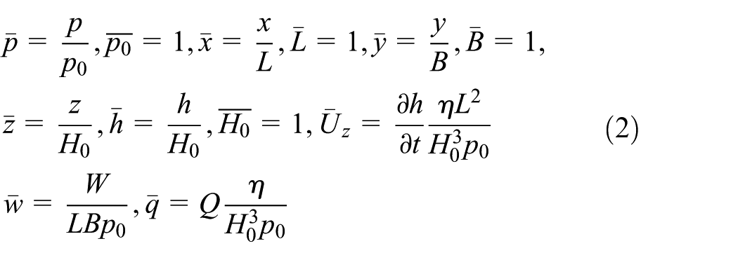
where, p is pressure, p0 is pressure in the oil pocket, h is film thickness, H0 is original film thickness, W is carrying capability, Q is volumetric flow rate, t is time, and η is viscosity. In addition,
The hydrostatic ram usually remains stable during machining process, so the variation of temperature, viscosity, and velocity can be ignored. The dimensionless Reynolds equation including film thickness variation and damping for analyzing carrying performance of oil pad on hydrostatic ram is shown in equation (3) 2

The Reynolds equation is approximated into algebraic equations and solved by Gauss-Seidel iteration in FDM. The iterative equation and coefficient matrix to solve numerical pressure distribution is shown in equations (4) and (5) 8
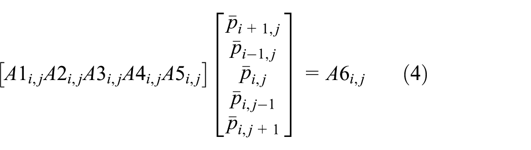

where

Dimensionless static supporting force is determined by numerical integration of pressure distribution on x and y coordinates. Dimensionless flow rate is calculated by numerical velocity field at the outer edge of oil pad. According to equation (2), static component and damping component of supporting force on single oil pad is shown in equation (7)

The dynamical equilibrium equation and RKM
The displacement of tool tip under dynamic cutting force is prerequisite for optimization. RKM is a widely used numerical method to solve ODEs like dynamic equilibrium equation. According to pervious researches,16,17 dynamic cutting force on heavy machine tools can be simulated as sine function. The equilibrium equation of the model shown in equation (1) is separated into sliding component and rotating component and shown in equations (8) and (9), respectively


where k is the numerical count of oil pad, Ft is dynamic component of cutting force, F0 is static component of cutting force, ω is frequency of cutting force. Equations (7) and (8) is second order ODE to describe the relationship between dzs, θ and time. Coefficient of RKM to solve second order ODE is shown in equations (10) and (11) 16
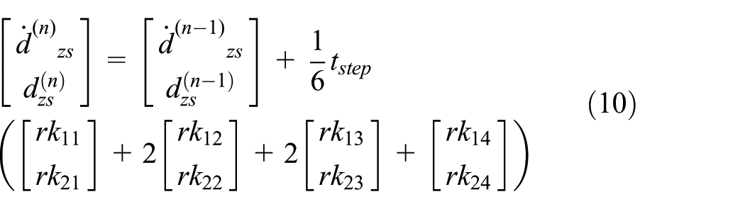

where tstep is the step length for the time coordinate and rkij is the computing coefficients of RKM. The tstep is set as 7.5×10⁻⁴s in the algorithm. Resolution of θ is similar to the process of equations (10) and (11). Criteria parameter λk is introduced to describe the variation of oil supply rate for optimization and γk is introduced to describe the variation of oil pad length, as shown in equation (12)

Dimensionless carrying force

Flow chart of the algorithm.
Numerical results and optimizing discussion
Damping component of single oil pad
According to the algorithm shown in Figure 4, the displacement of tool tip dz is obtained to evaluate the carrying performance of hydrostatic ram. Parameters are analyzed in order to minimize dz in optimization progress. Value of major parameters needed in computing is listed in Table 1.
Value of major parameters.

According to the value of L and B, the grid size is 5×5 mm and grid number is set as 2000 for each oil pad in FDM calculation. Static component of supporting force of oil pad is obtained by integration of pressure distribution directly. Damping component of supporting force is calculated by numerical differentiation of variation in supporting force under changing film thickness. The computing process of damping component of supporting force under different oil seal edge length Le is shown in Figure 5.
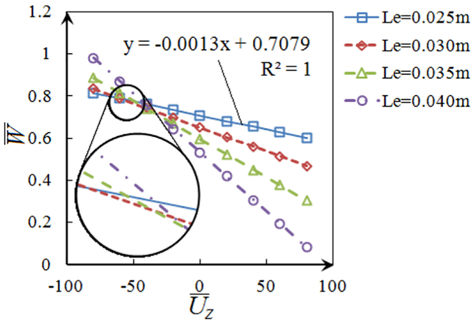
Damping component of single oil pad with different Le.
In Figure 5, dimensionless damping
Experiment of single oil pad
Hydrostatic ram is hard to conduct experiments because of its huge size. A small test devise for single oil pad is designed to verify the reliability of FDM solutions. Parameters like pumping flow rate and film thickness are changeable to simulate different conditions. The pumping rate is changed by throttle valve and measured by a flowmeter. Film thickness is adjusted by a lead screw with large reduction ratio. The film thickness varies 2 μm for every turn of screw hand wheel. Manometer, force sensors, and dial indicators are applied in this experimental devise. All measured data are stored by a real-time collector, as shown in Figure 6.

Experiment devise for single oil pad: (a) devise; (b) design; (c) oil pad.
A small oil pad is tested in this experimental instrument. The value of major parameters of it is shown in Table 2:
Value of major parameters in experiment.

Several measurements of carrying force and pressure are conducted under different pumping rate and film thickness. Average error between theoretical and experimental carrying force is 27.74%. All measured carrying force is smaller than calculation. Minimum error is 11.59% and it occurs when film thickness is about 100 μm. Average error of pressure is 17.54%. Minimum error 8.318% also occurs when film thickness is 100 μm. The comparison between theoretical and experimental results is shown in Figure 7.

Experimental results: (a) carrying force; (b) pressure.
Though there are errors between calculation and measurement, the relationship of factors is same as expected. This verification is instructive for the following optimization. Values of parameters for real hydrostatic ram are shown in Table 1.
Influence of oil supply rate on aspectant oil pads
The carrying ability of one pair of aspectant oil pads needs to be calculated before optimization progress. According to equation (6), the static component of supporting force is associated with oil pad size, oil viscosity, oil supply rate, and variation of film thickness caused by ram displacement. Oil supply rate control maybe a practical way to improve static stiffness because changes in oil pad size or oil type require more cost. Static supporting force of one pair of aspectant oil pads is the difference of carrying capability on each side, so film thickness is equal to δ when aspectant oil pads remain symmetrical. When oil supply rate becomes asymmetrical, equilibrium point of ram will shift to the side with less supply rate. The static supporting force and stiffness of one pair of aspectant oil pads under asymmetrical oil supply rate is shown in Figure 8.

Static supporting performance of one pair of aspectant oil pads: (a) static displacement of ram caused by asymmetrical oil supply rate; (b) influence of asymmetrical oil supply rate on supporting capability; (c) influence of asymmetrical oil supply rate on supporting stiffness.
In Figure 8(a), asymmetrical oil supply rate will cause static displacement of ram. But this kind of offset will not influence the precision because of the tool setting progress before machining. Due to the nonlinear characteristic of aspectant oil pads, asymmetrical oil supply rate will result in carrying performance changing. As shown in Figure 8(b), static supporting force W will decrease when ram is shifting under every asymmetrical case. The supporting stiffness will reduced at same time according to Figure 8(b). Therefore, symmetrical oil supply rate results in better static carrying performance of one pair of aspectant oil pads than asymmetrical case.
According to equation (6), damping supporting force is associated with oil pad length, oil viscosity, and film thickness variation rate caused by ram displacement. The damping supporting force and damping ratio of one pair of aspectant oil pads under asymmetrical oil supply rate is shown in Figure 9.

Damping property of one pair of aspectant oil pads: (a) influence of asymmetrical oil supply rate on damping; (b) influence of asymmetrical oil supply rate on damping ratio.
In Figure 9(a), changing of oil supply rate will not influence the damping component, unlike static component. Value of damping component remains unchanged and shifting with equilibrium position of ram. As shown in Figure 9(b), damping ratio ξ is changing with the variation of stiffness and damping caused by asymmetrical oil supply rate. But ξ remains greater than 1 in every case, namely the hydrostatic ram is over damping system. Therefore, symmetrical oil supply rate on one pair of aspectant oil pads is optimal for improving both static and dynamic performance of hydrostatic ram.
Discussion of optimal oil supply rate
Maximum absolute value of ram displacement dz under same cutting force impact is considered as evaluating indicator for optimization process. Smaller

Displacement of hydrostatic ram under cutting force impact: (a) maximum and dynamic deviation of dz; (b) sliding component and rotating component of dz.
In Figure 10(a), tow parameters are required to describe the deviation of dz: maximum displacement dzmax and dynamic waviness dzdyn. Smaller dzdyn means better dynamic performance and smaller dzmax means better static performance on hydrostatic ram. In Figure 10(b), sliding component of dz is 4 times greater than rotating component. Therefore, improvement in the rotational rigidity will be more efficient in reducing ram displacement, which requires variation of every oil pads shown in Figure 2. The optimization of rotational rigidity can be conducted by reallocation of oil supply rate. According to the conclusion of Figures 8 and 9, each pair of aspectant oil pads is set as symmetrical oil supply. The constraint condition is shown in equation (13)

λk is criteria parameter to modify oil supply rate as shown in equation (11). The maximum displacement of tool tip is changing with different oil supply scheme of oil pads 1 and 2 and oil pads 3 and 4, as shown in Figure 11.

Change of dzmax under different oil supply case: (a) dzmax under different λ12; (b) dzmax under different λ34.
In Figure 11, variations in oil supply rate are able to influence the supporting stiffness of hydrostatic ram. Increase in oil supply rate of pads 1 and 2 reduces
Comparison between optimal oil supply rate and optimal oil pad length
According to the results in Figure 11 and equation (6), variation of oil supply is able to improve static performance of hydrostatic ram to reduce dzmax, but not able to improve dynamic characteristic and restrain dzdyn. In optimization progress, more oil supply rate means more energy consumption. Because pads 1 and 2 and pads 3 and 4 have different contribution of stiffness improvement, optimal oil reallocation is able to reduce dzmax without extra energy consumption. The maximum pump rate of each oil pad in the model is limited within 5

The maximum displacement dzmax and dynamic waviness dzdyn of hydrostatic with optimization constraints under same cutting force impact is shown in Figure 12.

Change of dzmax and dzdyn under different optimal case: (a) dzmax and dzdyn under different oil supply rate; (b) dzmax under different oil pad length; (c) dzdyn under different oil pad length.
In Figure 12(a), absolute value of dzmax decreases when more oil flow rate is transferred from pads 3 and 4 to pads 1 and 2. Absolute value of dzmax decreases about 17.3% while λ12 increases 50%. But variation of λ12 changes dzdyn no more than 3%. So, oil supply reallocation is efficient to improve static performance of hydrostatic ram. In Figure 12(b) and (c), absolute values of dzmax and dzdyn both decrease when more pad length is allotted from pads 3 and 4 to pads 1 and 2. Searched by bisection method, optimal peak point of dzmax and dzdyn is obtained when γ12 = 1.469. Absolute value of dzmax decreases about 5.3% while γ12 increases 46.9% and absolute value of dzdyn decreases about 25.7% at the same time. So, pad length reallocation is efficient to improve dynamic performance of hydrostatic ram. Optimal cases are shown in Table 3 and Figure 13 by synthesizing the computing result. The case without any parameter changes is chosen as reference.
Comparison of optimal solutions.


Comparison of optimal solutions.
As the results shown in Table 3 and Figure 13, optimal oil supply rate is able to improve static performance by 17.3% and optimal pad length is able to improve dynamic performance by 25.7%. Static and dynamic characteristic of hydrostatic ram can be improved simultaneously when tow optimal suggestions is combined.
Conclusion
In present work, static and damping characteristic of hydrostatic ram on heavy machine tool is determined by FDM results of the Reynolds equation. Displacement of tool tip is obtained by RKM in order to evaluate carrying performance of hydrostatic ram. Optimal suggestions are proposed according to different contribution level of each pair of aspectant oil pads. Conclusions of this study are shown as follows:
Based on the analysis of the static component and damping component of supporting force on one pair of aspectant oil pads, symmetric parameters on both side performs better than asymmetric ones.
Improvement of rotational rigidity is efficient to reduce offset of tool tip position because rotation component is 4 times greater than sliding component of ram displacement. Pads 1 and 2 have more contribution to improve the rotational rigidity than pads 3 and 4. Therefore, ram displacement can be reduced by transferring oil supply rate from pads 3 and 4 to pads 1 and 2. When 50% oil supply rate is transferred from pads 3 and 4 to pads 1 and 2, static carrying performance improves 17.3% and dynamic performance only drops 0.7%. Oil supply reallocation is able to improve the static carrying performance without energy consumption.
When 46.9% oil pad length is allotted from pads 3 and 4 to pads 1 and 2, static carrying performance improves only 5.3% and dynamic performance increases about 25.7%. Symmetric pad length is able to improve the dynamic characteristic of hydrostatic ram without size variation of slide carriage.
Footnotes
Appendix 1
Handling Editor: James Baldwin
Declaration of conflicting interests
The author(s) declared no potential conflicts of interest with respect to the research, authorship, and/or publication of this article.
Funding
The author(s) disclosed receipt of the following financial support for the research, authorship, and/or publication of this article: The authors thank the National Natural Science Fund coded 51575009 for supporting the research.