
Abstract
Patients suffering from paraplegia are special disabled groups in society. In order to help them with lower-limb rehabilitation, a kind of power-assisted gait orthosis is designed. In consideration of the crutches that are rather necessary to keep balance when walking, the effects of crutches on analysis of mechanism cannot be ignored. Based on the gait characteristics, this gait orthosis mechanism is designed, of which the structure is optimized by genetic algorithm and the dynamical model is generated. The periodic movement of hip joints, knee joints, and ankle joints in corrected gait are achieved and the torque can be transferred to the driving force of the back motor and the pushrod according to the orthosis structure. Finally, a verification test shows this design is reasonable and practical.
Introduction
Spinal cord injury (SCI) is a serious disabling disease, which can cause paraplegia or quadriplegia. It makes patients lose their ability of standing and walking and seriously undermines their life quality. 1 In recent years, with the development of robot technology, it is possible for the paraplegic to have rehabilitation training with the assistance of a power-assisted gait orthosis (PAGO). The suitable structure design and optimization of gait orthosis are the key techniques to achieve the possibility.
PAGO is used to help the paraplegic with rehabilitation training, as well as assisting in walking. Patients need crutches to keep balance during PAGO ambulation. Swiss Federal Institute of Technology Zurich and HOCAMA, a Swiss company, jointly developed Lokomat,2–4 a light lower-limb rehabilitation training system, which was mainly designed for the patients suffering from SCI. Lokomat is composed of several modules, including a treadmill, mechanical legs, and a hanging weight-loss mechanism. Each mechanical leg, driven by an independent motor, has 1 degree of freedom, either in the hip joint or in the knee joint, which can restrain the movement in sagittal plane. Gait Trainer is another kind of lower-limb rehabilitation robot,5–7 driven by the end of limbs. Gait Trainer, with only 1 degree of freedom, approximately simulates the ankle joint motion law of the healthy, by optimizing structure parameters. Compared with the design in this article, Gait Trainer controls and drives the patients’ feet to make rehabilitation training, rather than bionic methods. Nowadays, the typical gait orthosis are “eLEGS,” 8 an exoskeleton system developed by American Berkeley Bionics Company in October 2010, and ReWalk, 9 a lower-limb exoskeleton designed by Amit Goffer of Israeli Argo Medical Technologies Ltd. “eLEGS” consists of exoskeleton parts and crutches, which is a simple structure and is convenient to use. A sensor is set in the crutch. The left exoskeleton leg moves forward with the forward movement of the right cane and vice versa. “eLEGS” not only can help the paraplegics to walk but also can help them train the lower-limb muscle and nervous system, which shows a positive clinical effect. “ReWalk” assists patients to walk on their own will, stand upright, walk, and go up and down stairs. It mainly consists of an exoskeleton system, sensors, and a backpack, assisting patients to keep balance by crutches. The patients can set the mode in advance, and the sensors can be activated by the movement.
Structure design is a key for electric orthosis. Currently, dynamic studies on lower-limb rehabilitation robots focus on dynamical analysis of human body models. 10 One of the models consists of trunk, bilateral thighs, and bilateral shins. As for the other one, the feet are included.11–13 However, in the analysis process, the crutch effect is ignored. Furthermore, different walking gaits with crutches can also influence the results. Therefore, it is essential to build reasonable dynamic models in various gaits with crutches. The dynamic model established in this article considers the effect of the crutches.
Based on the analysis of gait characteristics when the paraplegic walk with crutches, this article designs an orthosis mechanism and optimizes the genetic algorithm structure. After that, the dynamic model is built to make the periodic movement of the joints’ driving torques in corrected gaits. According to the orthosis structure, the torque is transferred to the driving forces of the back motor and the motor-driven pushrod. Finally, its reasonableness and practicality are verified by experiments, and the analysis validity is proved.
Gait characteristic analysis of lower limbs
Hip joint consists of a femur with a rounded head and a cup-like acetabulum of the pelvis. It is a multiaxial ball joint, which can make flexion and stretch, adduction and abduction, and internal and external rotation. Knee joint contains a distal femoral articular surface, an upper tibial articular surface, and a patellar surface, which can make flexion and stretch. Ankle joint includes a tibia, a fibula, a calcaneus, and a talus, which can make dorsiflexion and toe flexion and internal and external rotation. 14 In a normal gait, lower limbs mainly move in the sagittal plane. Therefore, the motion in other planes can be neglected. In the walking period, the dynamic characteristics are rather different between the support and the swing phases. 15
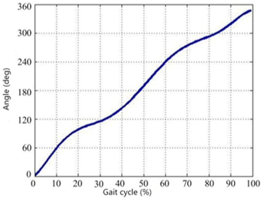
The gaits of the paraplegic walking with crutches are shown in Figure 1. At the beginning of a period, the two crutches prop forward simultaneously, and the angles between the crutch and the ground are the same. Then, the lower limbs can make the movement with normal gaits.

Two crutches move together.
Structural design of the orthosis
A PAGO includes the hip, knee, ankle joints, thigh, shin bars, and foot plates. The structure of orthosis hip is shown in Figure 2. Usually, motors are installed on both sides of orthosis hip. To simplify the structure, only one motor is equipped in this orthosis hip to drive alternating movement of bilateral lower limbs. The crank-link mechanism on the back is AHBH. The motor drives AHAH″ rotating on the crank slider and LH2 reciprocating swing, which can make the back rocker swinging up and down. Meanwhile, the back-rocker rotation joint is the input end of the structure, which is shown in Figure 6, making the rotation of hip joints in the sagittal plane. The mechanism on both sides is completely symmetrical and can keep reciprocating and alternated movement, which meets the basic requirement of hip joints.

Space four agencies of hip in the gait.
Electromotive handspikes control the knee and ankle joints. Compared with a motor, electromotive handspikes stabilize joint movements. The two ends of the electromotive handspikes in the knee joint are, respectively, connected with the thigh and shin bars by joints. The two ends of the ankle-joint handspikes link to the shin bars and foot plates by joints, respectively. The electromotive handspikes, connecting with the joints, form the four-bar mechanism, which contributes to the flexible movement. The PAGO structure design is shown in Figure 3, and the prototype is shown in Figure 4.

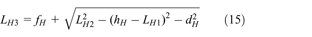
Schematic diagram of a power-assisted gait orthosis.

Experimental prototype of power-assisted gait orthosis.
Electric gait orthosis hip has a bilateral space, together with a four-bar mechanism and a crank-rocker mechanism. In order to obtain the hip as an input, based on the law of the healthy people gait, the movements need to be analyzed.
According to the structure design of the lower-limb exoskeleton robot, the rotation axis of hip is perpendicular to the rotation axis of the back rocker. According to Hua, 16 the model of the hip on the right can be simplified as shown in Figures 5 and 6. In Figure 5, the schematic diagram of the four-bar structures is displayed and in Figure 6 simplified schematic in one plane is provided.
Equivalent plane of four-bar structure.

Crank-rocker mechanism in the back.
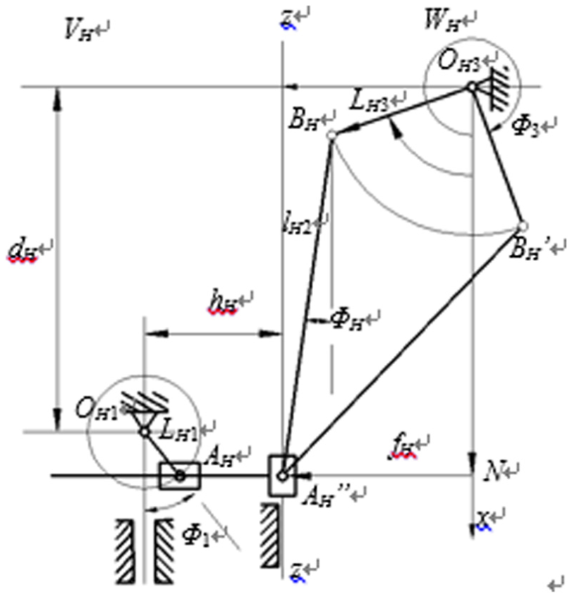
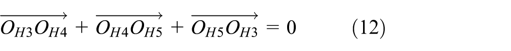
The related coordinate system is presented in Figure 5. The origin of the coordinate system is just the hip rotation center. x-axis coincides with the axis of rotation and points to the body and y-axis vertically downward. According to the right-hand rule, the direction of the z-axis can be determined. OH1 represents right-hip rotation joint. Φ1 represents hip rotation angle. OH3 represents the rocker rotating backward. Φ3 represents rocker rotation angle. Point AH and point BH represent two ball joints, based on which plane VH and plane WH are established perpendicular to OH1 rotation axis and OH3 rotation axis, respectively. These two planes intersect with each other on axis zz. AH projection on the plane WH is AH″, which is on line zz. When the active lever rotates around the OH1AH axis, the movement of AH is circular motion whose center is OH1 and its radius is LH1. Its projection AH″ reciprocates along the axis zz. On plane WH, rocker-slider mechanism OH3BHAH is designed. The length of OH3BH is LH3. The length of BHAH″ is lH2, which is variable as shown in Figure 5. On plane VH, the bar mechanism is designed and the movement of guide bar is the same as AH″ movement.
From Figure 6, point A″ is equal to a motion pair; therefore, it can be expressed as

where dH represents the vertical distance between the rotation pair OH1 and OH3 along y-axis.
In the rocker-slider mechanism on WH plane, lH2, the length of bar BHAH″, is variable. In the triangle AHAH″BH

In the equation, AHAH″ = hH − LH1sin Φ1. The length of BHAH″ can be represented by equation (3)

According to Polygon OH3BHAH″NH, on WH plane, the location equation can be represented as

Eliminating ΦH from equation (4), the equation can be depicted as

where
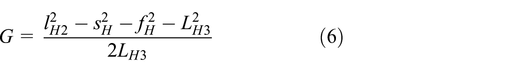
From equation (6), the output angle of the rock in the back can be obtained

As for the crank-rocker mechanism, Φ3, the output of equation (7), is the input angle. The output of the crank-rocker mechanism is crank angle. Finally, the law of the crank movement can be achieved, when it is in a normal gait. The crank-rocker mechanism is shown in Figure 6.
In Triangle OH3OH4OH5, according to the sine theorem, equation (8) can be represented as

Then

Finally, the law of the crank movement can be acquired.
The four-bar structure of knee is shown in Figure 7.
Schematic diagram of the four-bar structure of knee.
The location equation is

From equation (10), it can be derived that
According to the analyses above, the movement law of hip and knee and the law of the driving mechanism’s movement can be found. According to the structure design, the lengths of all the bars in exoskeleton robot are shown in Table 1 and Table 2.
Hip joint parameters of the exoskeleton robot (cm).

Knee joint parameters of the exoskeleton robot (cm).

Taking the above parameters into kinematic analyses, the rotation law of the back-crank hip joints and the law of electric-driven movement on knee joints can be gotten. According to the movement law, the gait of limb-exoskeleton robot is similar to that of a healthy person. The laws of the rocker and crank in the backward movements are shown in Figures 8 and 9, respectively. The law of electric-driven movement on the knee is shown in Figure 10.

The backward movement law of the rocker.
The backward movement law of the crank.

The electric-driven knee movement law.
From Figure 9, it can be seen that the motor changes linearly. Therefore, when the motor rotates at a constant speed, the criterion can be reached, and both sides of the hip joint approximately redo the same movement. From Figure 10, the maximum length is nearly 158.8 mm, and the minimum is 65.6 mm. As the electric-driven length increases, the knee-joint movement is the same as that of a healthy person. Therefore, it can actually benefit the patients and help them to recover.
Optimization of exoskeleton robot structure based on kinematics
Parameter optimization on the hip-joint movement law
Optimization of the hip-joint movement is to make the patients wearing lower-limb exoskeleton robot walk more comfortably. After the related parameters are optimized, the hip movement is much closer to the healthy person gait, at a constant speed.
From the analysis, it can be seen that the hip-joint mechanism of lower-limb exoskeleton robot consists of a crank-rocker mechanism and a spatial four-bar linkage. As for the crank rocker, the kinematic analysis can be represented as
The rotation angle of the rocker can be derived from equation (12)

where Φ3 is the rocker rotation angle, Φ4 is the crank rotation angle, relative to the vertical direction, r1 is the crank length, and r2 is the distance between OH3 and OH5.
As for spatial four-bar linkage RH1-SH1-SH2-RH2, when the rotation angle of rocker arm is the input, the rotation angle of the hip joint can be expressed as

where


where Φ4 is motor rotation angle, which is constant. LH1 is the fixed distance between two hip joints. The rotation location of the exoskeleton robot hip joint is designed by real parameters. Therefore, dH, hH, and fH are constants. In addition, there is a coupling relationship between LH2 and LH3. According to the spatial kinematics analysis of the four-bar linkage, the relationship can be expressed as
Optimization is based on genetic algorithm. In the process, the control parameters of genetic algorithm are as follows: the individual number is 40, maximum genetic algebra is 500, variable binary digit is 20, and crossover rate is 0.9. According to the actual situation of the lower limbs, dH = 53 mm, hH = 45 mm, fH = 185 mm, and LH3 = 185 mm.
After optimization, the parameters can be obtained by specific values. r1 = 17.1423 mm, r2 = 250.3868 mm, and LH2 = 41.0041 mm.
The original parameters are listed here in order to compare with optimization. r1 = 28 mm, r2 = 220 mm, and LH2 = 50 mm.
The results are shown in Figures 11 and 12.

The movement law of hip joint.

Hip-joint deviation.
Parameter optimization based on knee-joint movement law
Parameter optimization method
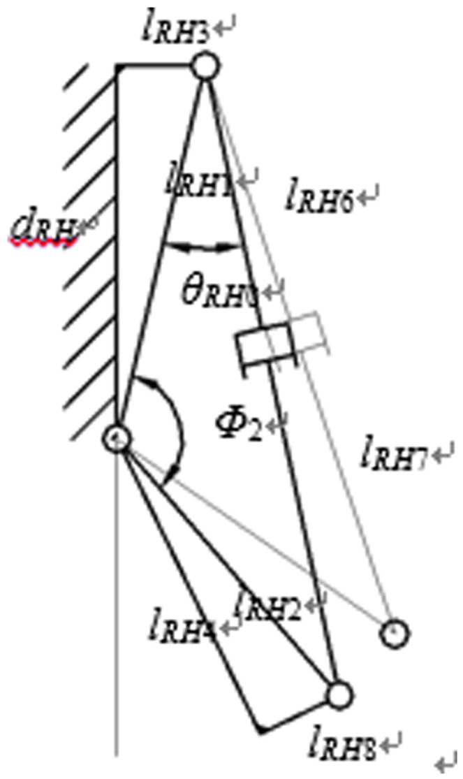
The surface between femoral and tibia is irregular. Therefore, there are both rolling and sliding situations on the surface, as the knee flexes and stretches.17,18 According to design principle of lower limb, four-bar linkage is used to replace the knee joint. It can be regarded as the human knee joint.19,20 In order to control steadily, knee joint of exoskeleton robot can be designed as uniaxial knee joint. Therefore, the deviation is inevitably generated between the exoskeleton robot and the human body, when walking. There are two major factors to be discussed. One is the noncoincidence of the end trajectories. The other is the angle between the exoskeleton robot leg rod and the human leg. This angle should be designed much smaller, as the end trajectory is closer as much as possible.
Exoskeleton robot lower limb and human lower limb are, respectively, shown in Figure 13(a) and (b). Four-bar linkage knee joint is shown in Figure 13(c). Its kinematic analysis is introduced by Han and Wang. 13 l4R1 = 43.5 mm, l4R2 = 35.00 mm, l4R3 = 50.77 mm, and l4R4 = 20.62 mm.

Exoskeleton robot lower limb and human lower limb: (a) exoskeleton robot lower-limb model, (b) human lower-limb model, and (c) four-bar linkage knee-joint model.
In order to compare the end trajectory of the exoskeleton robot lower limb with that of the human lower limb, their kinematic equations need to be solved. The kinematic equation of exoskeleton robot lower limb is

Therefore, exoskeleton robot can be expressed as

where Φ1 is the rotation angle of exoskeleton robot hip joint, Φ2 is the rotation angle of exoskeleton robot knee joint, lb1 is the length of exoskeleton robot thigh, and lb2 is the length of exoskeleton robot calf.
For human lower limb, the kinematic equation is

Therefore, the expression of human lower limb is

where


where θR1 is the rotation angle of human hip joint, θR2 is the input angle of human four-bar linkage knee joint, θR3 is the angle between l4R3 and l4R4, lb3 is the length of human thigh, lb4 is the length of human calf, and A and b are the projection lengths in the x- and y-axis in the original condition, respectively.
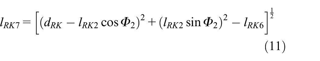
In addition, θR4 is the intermediate variable in the solving process of four-bar linkage of the knee joint

where


Meanwhile, in order to compare the trajectory of the exoskeleton robot lower limb with that of human lower limb, the angle between the exoskeleton robot leg rod and the human leg should be much smaller as the end trajectory is closer.
The angle between the exoskeleton robot leg rod and the human leg can be expressed as


where

From the above analysis, kinematic expressions of exoskeleton robot lower limb and human lower limb, as well as the angle between robot and human, are determined by lb1, lb2, lb3, lb4, Φ1, Φ2, θR1, θR2, and related parameters of four-bar linkage. Parameters of four-bar linkage in knee joint are fixed, as well as the input angle of human hip joint and length of thigh and calf. As for the exoskeleton robot, the input angle of hip joint can be obtained from optimization. The length of thigh and calf should be same as the length of human lower limb. Then, lb1 and Φ2 are defined.
Objective function and optimization method
Optimization design of exoskeleton robot knee joint aims to make patients more comfortable. The trajectory of exoskeleton robot lower limbs should be much more similar to that of human lower limb, and the angle should be much smaller.
One cycle movement of the human knee joint is divided into n parts, and the optimal function is

where F2 is the square of angle in one cycle and F3 is the square of terminal position difference in one cycle.
According to the realities of exoskeleton robot, the constraint of the algorithm can be expressed as

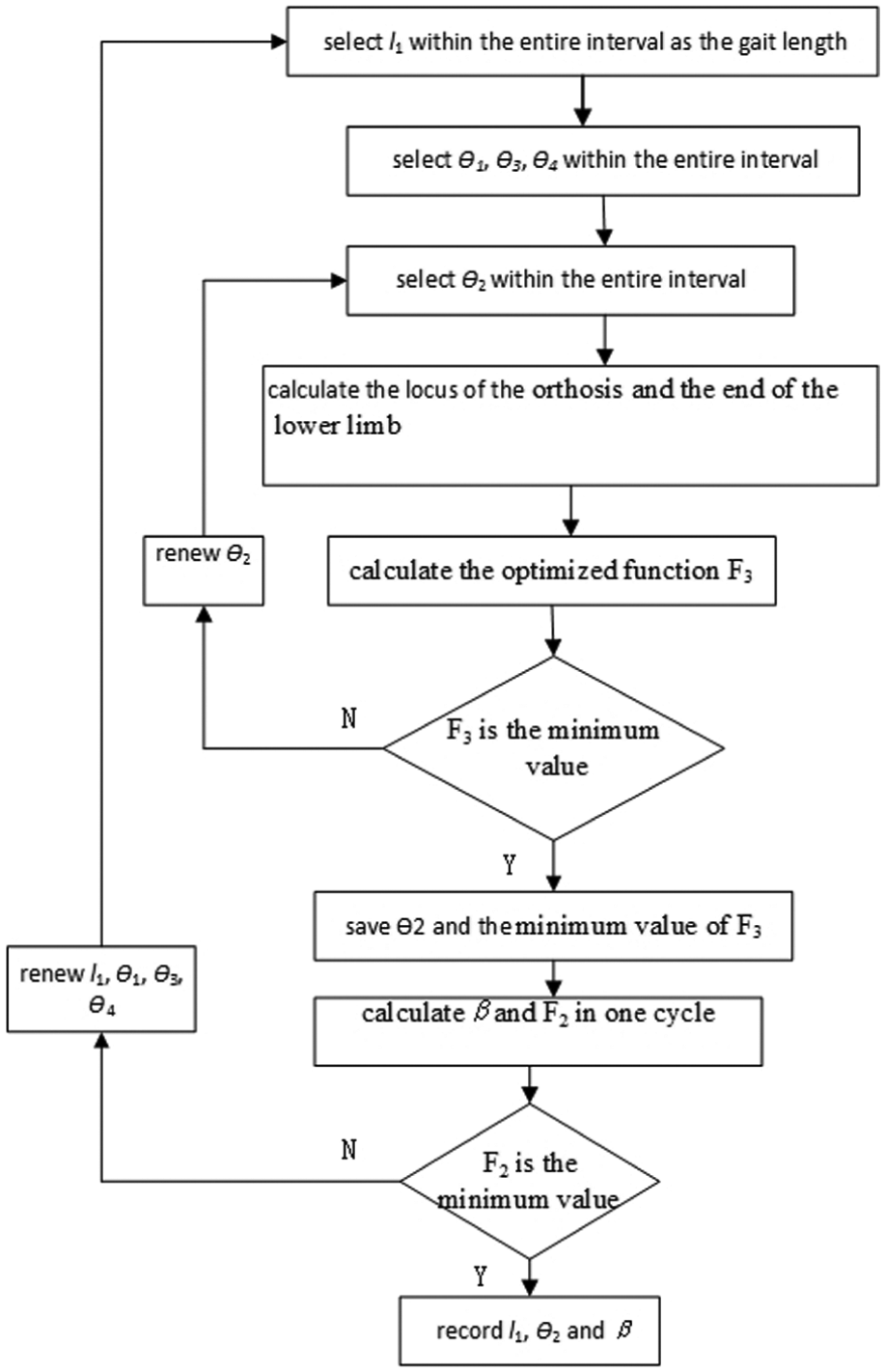
The optimization method is introduced in detail in Figure 14. One cycle movement of the exoskeleton robot knee joint is divided into n parts. lb1 is divided into m according to the specific step in an appropriate range. When minimum Φ2 is obtained by F3, the angle β can be determined. After continuous cycle and comparison, the optimal values (β, lb1, Φ2) can be obtained.
Optimization flow of exoskeleton robot knee joint.
Optimization test of knee joint
Assume that the object’s height is H = 170 cm, thigh length is lb3 = 416 mm, and calf length is lb4 = 418 mm. The movement law of hip joint is found, based on healthy human gait. Thus, the movement law of exoskeleton robot hip joint can be optimized.
This parameter, lb1 = 354 mm, can be optimized. The deviation between change law of Φ2 and movement law of knee joint at a normal gait is shown in Figure 15. The input angle of human knee joint cannot be used for exoskeleton robot directly. The input angle should be optimized as Φ2.

Optimization results of knee joint: (a) optimization results of knee joint and (b) angle deviation of knee joint.
After these parameters of exoskeleton robot knee joint are optimized, the optimization effectiveness can be analyzed through objective functions. Before optimization, lb1 equals 420 mm. The movement law of exoskeleton robot lower limb and human lower limb at a normal gait is shown in Figure 16.

(a) Gait trajectory and (b) included angle before and after optimization.
In Figure 16, it can be concluded that gait trajectory of exoskeleton robot lower limb is closer to that of human lower limb and the angle deviation is much smaller after related parameters of exoskeleton robot lower limb are optimized.
Establishment of the dynamic model
Dynamics analysis
PAGO is an equipment designed for patients suffering from paraplegia. The simplified model includes the trunk, bilateral thighs, bilateral shins, two feet, and two crutches. The projections of the two crutches on XY surface coincide with each other. As the simplified model shown in Figure 17, the fixed coordinate system is set up in the area, where the crutch contacted the ground. x0-axis is horizontal and y0-axis is vertical. The quality of each connecting rod is represented by mi(i = 1, 2, …, 6). The quality of the orthosis can be analyzed as the weight loading. The length of Crutch 1 and 2 is l1 and l2, respectively. The length of the trunk (from the revolute joint of the crutch to the revolute hip joint) is l3. The length of bilateral thighs, shins, and feet is l4i, l5i, l6i(i = 1, 2), respectively.

Simplified model with double crutches.
The dynamic analysis is converted to a simplified model. During the movement, assume that the hip joint moves horizontally. θ1 is the angle between the x0-axis (positive direction) and Crutch 1. θ2 is the angle between the x0-axis (positive direction) and Crutch 2. θ3 shows the angle between Crutch 1 and the trunk along the positive direction of y3. v is the movement speed. Therefore, θ1 and θ2 can be expressed as

where
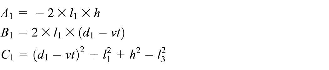
where d1 is the horizontal distance from the hip-joint revolute joint to the original point of the fixed coordinate system and h is the vertical distance from the hip-joint revolute joint to the ground. The angle between Crutch 1 and the trunk toward the positive direction of y is then expressed as

The movement of the hip, knee, and ankle joints has defined laws. The calculated centroid positions of the bars are as follows


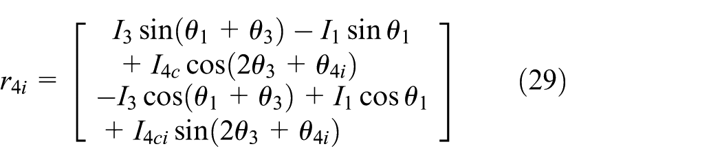
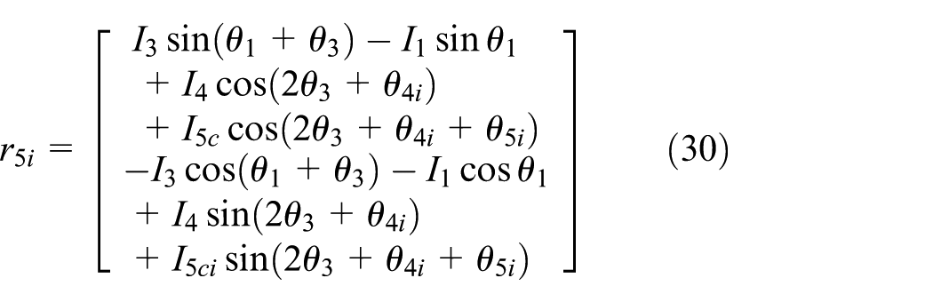
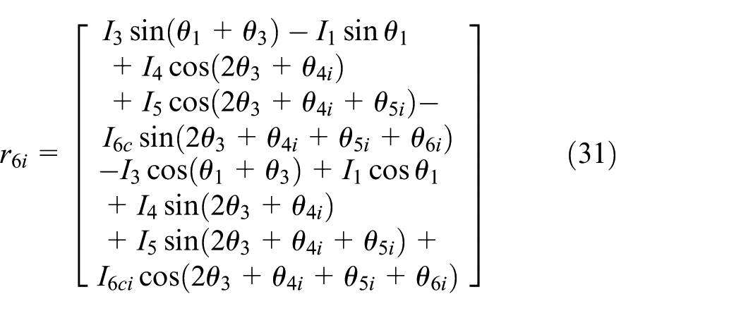
where ri(i = 1, 2, 3, 4, 5, 6) represents the vector from the fixed coordinate system to the No.i rod centroid, respectively. lnci(n = 1, 2, …, 6) represents the length from the No.i rod centroid to No.(i − 1) coordinate system, respectively. θ4i, θ5i, and θ6i, i = (1, 2), represent rotation angles of the hip, knee, and ankle joints, respectively. In equations (3)–(7), i = (1, 2) represents bilateral crutches and lower-limb connecting rods.
Dynamics modeling
Among various methods to build dynamics models, Newton–Euler method is the fastest, which is able to solve the counterforce of connecting rods. Therefore, it is applied to establish the dynamic model. After dynamic model simplification, the force analysis of connecting rods is shown in Figure 18.

Force and torque in the linkage.
Every connecting rod, including trunk, thigh, and shin rods, is under stress, from the forces and moments of associated rods, as well as gravity, inertia force, and inertia moment. As for the trunk connecting rods, due to the coincident position of two crutches, they can be regarded as one crutch when calculating. The force balance equation of every connecting rod in its own dynamic coordinate system is expressed as follows 14

where ifci is inertia force of the component,
The moment balance equation is as follows
where inci is the inertia moment of the component, ini is the moment of No.(i − 1) component exerting on No.i component, ini + 1 is the moment of No.(i + 1) component exerting on No.i component.
The above inertia force and moment expressions are based on the study by Zhong and Zhu. 21
When lower limbs are under pressure, the force and moment equations of foot connecting rods are as follows

where Fni is the external force of No.i connecting rod. When lower limbs swing, the external force is zero.
For bilateral crutches, the balance equations of force and moment are as follows

The driving moments of the hip, knee, and ankle joints in Gait 1 can be solved by combining all the above equations.
Verification experiment of lower-limb exoskeleton robot
The reliability of the systemic mechanical properties can be tested on the experiment platform. The rationality of the optimized structure designed above, the accuracy of the kinematic analysis, and the dynamic model prove that it is a new design and test method of equipment for the patients who suffer a spinal injury.
Non-load test
The exoskeleton robot also needs to be taken plenty of no-load experiments to test reliability of the structure and stability of the machine, as well as the rationality of the platform, before being applied to experimenters.
The no-load test is to verify the availability of braking device and the stability of control system, especially the active control. All the data are gathered in the stable state. Meanwhile, substantial relative curves of hip and knee joint angles are collected in several gait cycles, within 60 s.
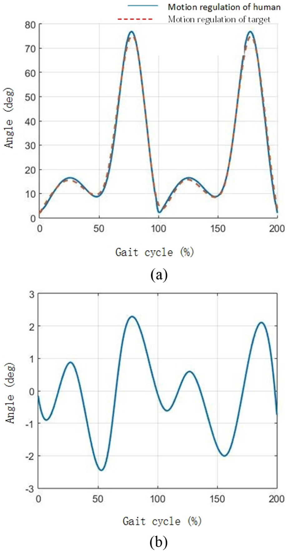
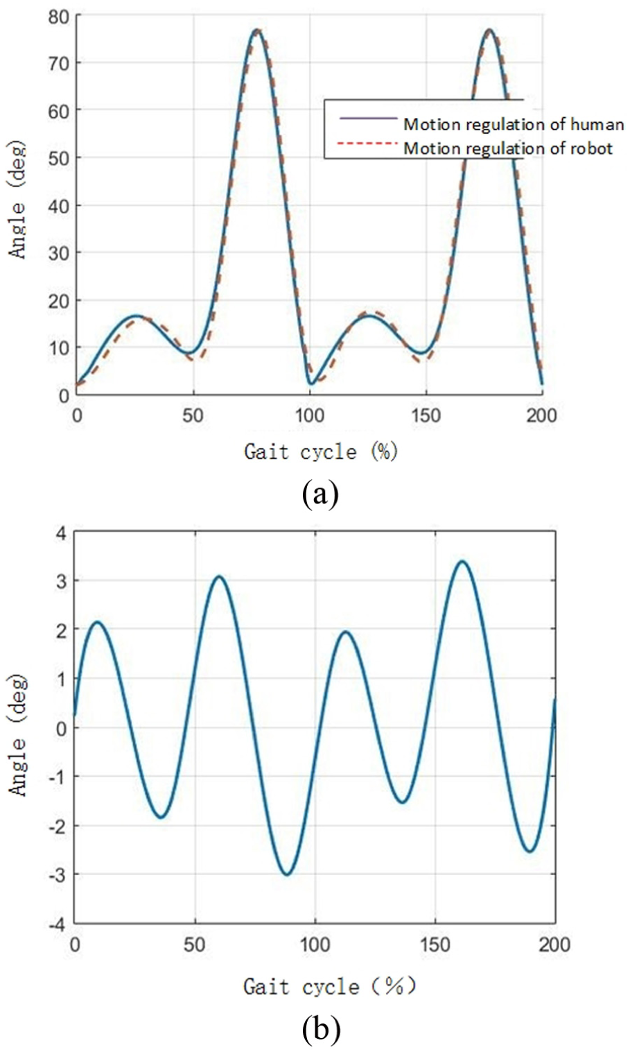
Figures 19(a) and 20(a) show the angle change rule of the exoskeleton robot hip and knee joint, respectively, in the first 2 gait cycles. The solid line shows the target data of the hip and knee joint angle change rule, whereas the dotted line depicts the relevant data of exoskeleton robot joints, measured by an encoder in no-load state. Figures 19(b) and 20(b) reflect the difference between movement law and the hip and knee joint target data, in the first 2 gait cycles. In addition, the knee joint target data are an input curve after optimization.

(a) Deviation and (b) difference of the hip-joint movement law.
(a) Deviation and (b) difference of the knee-joint movement law.
As the Figure 20 shows, there is some certain difference, which is a slight fluctuation in both positive and negative intervals, between the experimental data and the target data. The maximum absolute error of hip and knee joint is 4.82° and 2.25°, respectively.
The primary causes of the deviation between the movement law of human and machine are pointed out as follows:
The dominant factor that causes the inevitable deviation of hip joint is that the mechanical movement law of both sides of the hip joint is invariably symmetrical in one gait cycle, whereas the human movement law is not exactly symmetrical.
The gap errors in mechanical assembling of exoskeleton robot generate in the connection of mechanism and joints of bearings.
Control and measurement errors come from the insufficient accuracy of control system and the encoder.
Conclusion can be made based on the result of the no-load test. The angle change rule of hip and knee joints in the no-load test is almost corresponding to the target data of gait. And the error is generally in a reasonable range. The result can certify the rationality and functionality of the robot gait design, as well as the security and accuracy of the control system, which contributes to the next test on experimenters.
Movement gait test
The experimenters, selected for the test, is a group of healthy people, 175 ± 3 cm in height and 65 ± 3 kg in weight. Under the active control, the data are gathered in the stable state, within 60 s. Meanwhile, angle change curves of hip and knee joint are collected in several gait cycles and are all saved in the computer.
Figure 21 is a complete cycle. Circulating the gait cycles, the experimenter walked with the help of lower-limb exoskeleton robot.
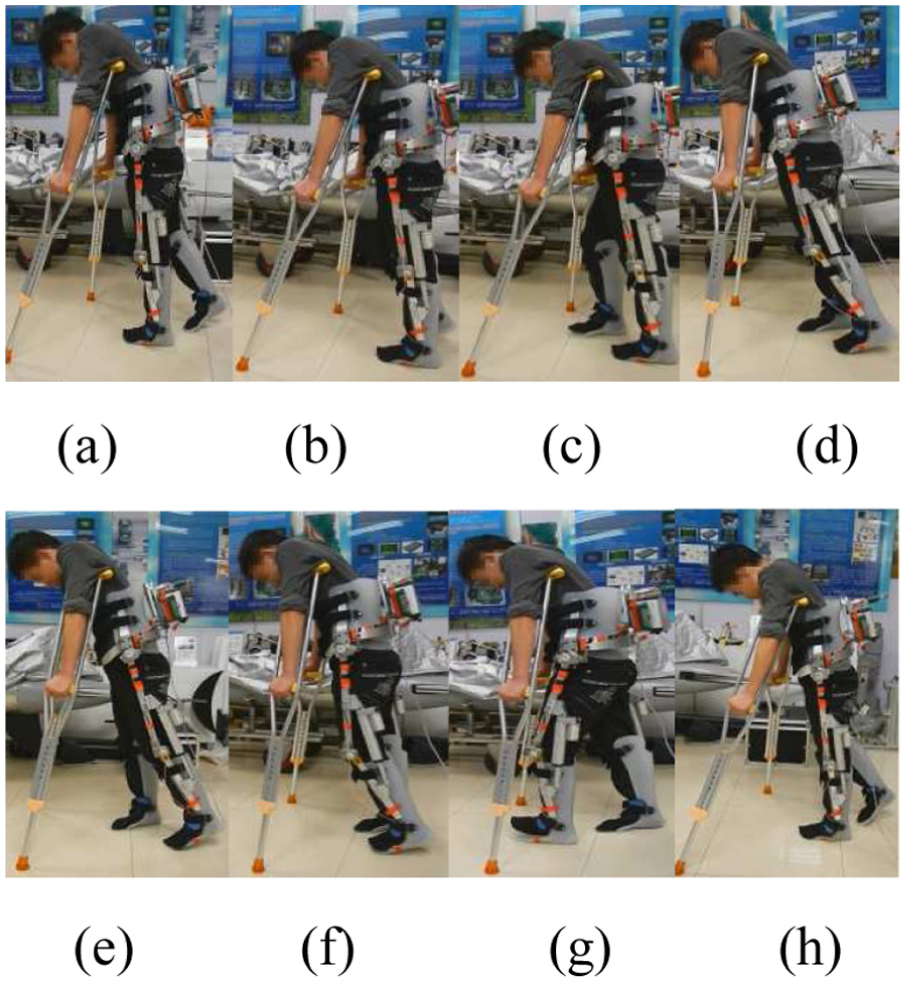
Lateral view of the experimenter wearing orthosis: (a) the right toe leaving the ground, (b) the right leg entering the swing phase, (c) the right heel landing, (d) the right sole pushing the ground, (e) the left toe leaving the ground, (f) the left leg entering the swing phase, (g) the left heel landing, and (h) the right toe leaving the ground.
Figures 24 and 25 are plotted based on the test, where the velocity of movement is approximately 1.4 m/s. Figures 13(a) and 14(a) show the angle change data of exoskeleton robot hip and knee joints, respectively, in the first 2 gait cycles. The solid line depicts target data of human hip and knee joints, whereas the dotted line is plotted by the data of exoskeleton robot, measured by encoder. Figures 22(b) and 23(b) reflect the difference between the data measured and target data of hip and knee joints.

Angle and deviation of hip joints wearing orthosis: (a) angle of hip joint and (b) angle difference of hip joints.
Angle and deviation of knee joint wearing orthosis: (a) angle of knee joints and (b) angle difference of knee joints.
From the figures, it can be seen that the movement deviations of hip and knee joint increase slightly, when experimenters move wearing exoskeleton robot, compared with that of no-load test. The maximum absolute error of hit joint is 6.45°, which is 1.63° more than that of no-load test. As for the error of knee joint, the two data are 3.20° and 0.95°, respectively. There are two primary reasons. Besides the basis of the no-load test itself, the other is the subtle distortion of the metal structure, because the major structure is made of aluminum, in spite of its advantage of lightweight.
The robot joint angles are compared according to different velocities. In the test, the velocities of the experimenter are 1.2 and 1.4 m/s. The movement law and deviation of hip joint and knee joint are plotted as follows.
Figures 24 and 25 depict that the deviation of joints is smaller when the speed of experimenters decreases and the movement keeps stable at the same time. On the contrary, as the speed of experimenters increases, the fluctuation is in an upward trend, which causes larger movement deviation. The maximum absolute error of hip joint is 5.44°, when the velocity is 1.2 m/s, which is 0.62° larger than that of the no-load test and is 1.01° smaller compared with the test, whose velocity is 1.4 m/s. The maximum absolute error of knee joint is 2.90°, when the velocity is 1.2 m/s, which is 0.65° larger than that of the no-load test and is 0.30° smaller compared with the test whose velocity is 1.4 m/s. The maximum absolute error of hip and knee joints is 6.4° and 3.2°, respectively, when the velocity is 1.4 m/s.

Hip-joint movement law and deviation of different velocity.

Knee-joint movement law and deviation of different velocity.
The reason is that the inertial force and inertial moment of the robot’s mechanical components have an impact on the movement, whose state changes as the velocity changes. Furthermore, the inertial force and inertial moment will rise if the speed increases, which also causes a larger angle error. To the opposite, if the speed is slower, the inertial force and inertial moment will decline, which has a slighter influence on the precision of movement. However, it can be seen from the figures, whether the velocity is 1.2 or 1.4 m/s, the movement amplitude can be controlled, which actually meets the requirement of the application.
Test on the performance of sustained movement
Sustained movement is one of the most significant performances of the exoskeleton robot. To be more specific, the robot needs to keep high precision to make the rehabilitation training and movement during a completed training cycle, rather than a large deviation affecting the performance of the system, which may cause a secondary injury. Therefore, it is quite crucial to test the sustained movement of exoskeleton robot. The key point is to find whether its movement still meets the requirement or has a large deviation for a long duration of usage.
Select healthy people of the same height and weight as movement gait test experimenters. First, set 1.4 m/s as the velocity of the movement. Next, measure the angle changing curve of hip knee joint. Finally, plot the figure based on the data collected from two cycles in the measurement. The data are recorded and analyzed at 10, 20, and 30 min from the total duration of 30 min. Then the difference can be calculated when comparing the target data with the data from the measurement. Figures 26 and 27 show the movement difference statistical data of hip joint at 1.4 m/s and knee joint at 1.2 m/s, respectively.

Movement deviation of hip joint at different time.

Movement deviation of knee joint at different time.
As can be seen from the test, the angle deviation of hip and knee joint has an upward trend as the test develops. Thereinto, the maximum difference of hip and knee joint is 6.72° and 3.81°, respectively, in the first 2 cycles at 10 min, whereas 8.12° and 4.21°, respectively, at 30 min. Overall, during the long period of movement, the movement system remains in a stable state, despite the angle deviation in a small range, which has a very limited impact on the movement of lower-limb exoskeleton robot. That is to say, lower-limb exoskeleton robot has a satisfactory performance of sustained movement.
Load verification experiment
The pressure test on the experiment platform is to test whether the heaviest load that lower-limb exoskeleton robot could bear meets the design requirement. To be more specific, it is to check out the errors that the system may occur and the stability of the data from the measurement system, as the weight of load rises. The ultimate aim is to test the steadiness when a sudden external force imposes on and the reaction of lower-limb exoskeleton robot when it is used by various people of different weight.
The changing angle curves of hip and knee joint can be measured as heavy load of different weights bound onto experimenters’ legs. In the test, set 1.4 m/s as the movement gait cycle, 3 min as the total duration and added 3 and 5 kg, respectively, to experimenters’ leg, by binding sandbags. Then, collect the data when the system remain stable and plot the difference figure, by comparing target data with the data from the measurement. Figures 28 and 29 show the movement law of hip and knee joints in the first 2 cycles.
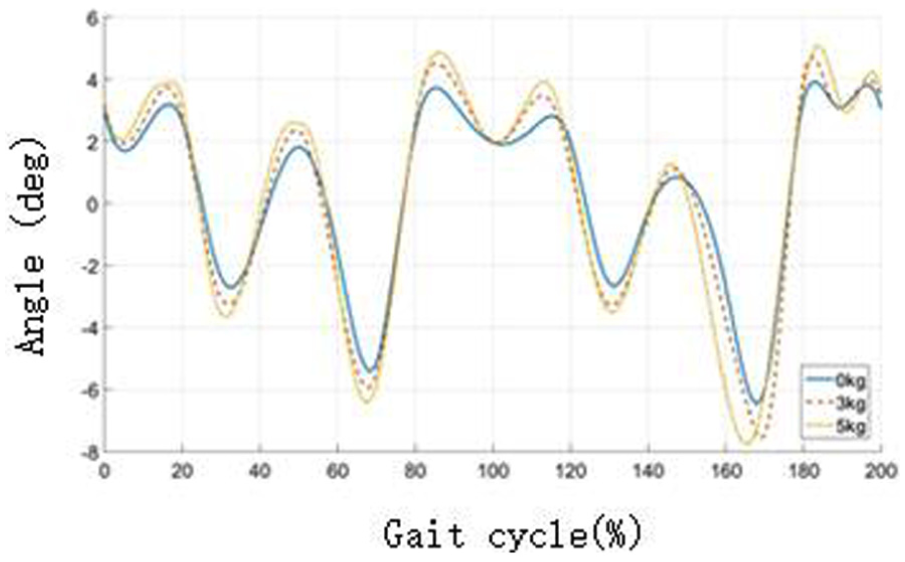
Movement deviation of hip joint under different loads.
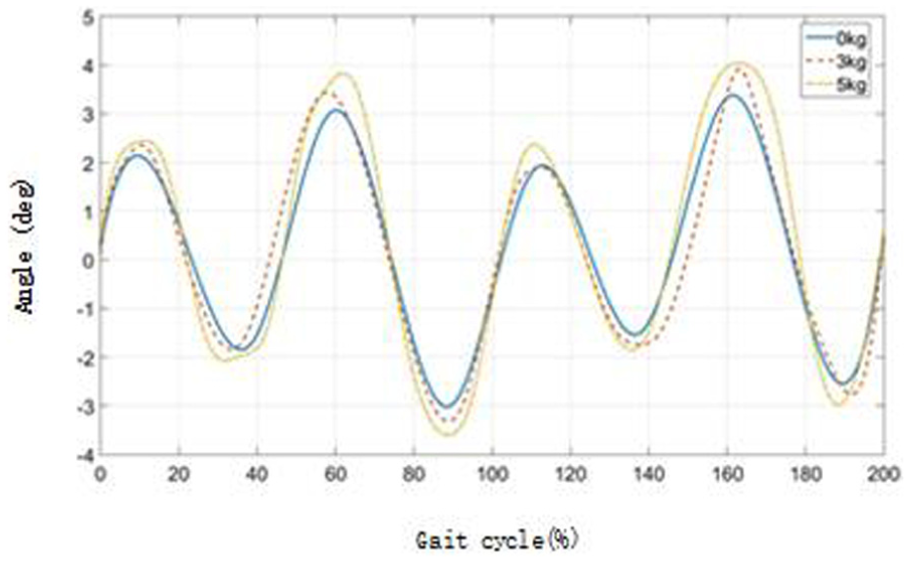
Movement deviation of knee joint under different loads.
It can be seen from the figures that the angle deviation of hip and knee joints increases due to the increasing weight of load. The maximum deviation of hip joint under 3 and 5 kg of load is 7.3° and 7.6°, respectively, whereas that of knee joint is 3.87° and 3.98°. It is mainly because of the error caused by the slight deformation of robot structure. On the whole, the movement law of hip and knee joints is generally stable and has limited errors, which does not affect the regular movement of lower-limb exoskeleton robot. Therefore, the lower-limb exoskeleton robot has a strong anti-interference performance.
Discussion
Instead of the existing method of adding double motors on the hip joints of lower-limb exoskeleton robot, our original design on the driver unit is to use a crank-rocker mechanism connecting with the spatial four-bar structure, based on the joint structure feature, which efficiently drives both sides of hip joints reciprocating movement.
Compared with the common methods, using only one motor to drive both sides of hip joints reciprocating swing at the same time reduces one motor, loses much weight, and simplifies the structure. Meanwhile, the movement of hip joints is controlled by the power-driven pushrod rather than the motor. Because of its restriction on moving distance and the self-locking feature, the whole movement becomes more stable. In order to acquire a more reasonable result, genetic algorithm is used to optimize when deciding the length of the link mechanism, which can provide a theoretic guarantee for the experiment. Finally, the verification test shows the rationality and reliability of the design, and more practicability is proved, compared with other designs that have not been tested.
Conclusion
Paraplegic patients usually need crutches to keep balance, when they walk with gait orthosis or take a rehabilitation training. Therefore, it is necessary to establish a crutch-included dynamic model. This article analyzed the gait characteristics with crutches, designed the mechanical architecture, and optimized the genetic algorithm. Moreover, the performance of the design is verified under many external conditions, such as no-load, gait movement, long-term continuous movement, and load tests. The results show that the design is reasonable. It is a good option for paraplegic rehabilitation training in the future. Meanwhile, the model and the above analyses are proved reasonable and have a reference value for further research.
Footnotes
Academic Editor: Nicolas Garcia-Aracil
Declaration of conflicting interests
The author(s) declared no potential conflicts of interest with respect to the research, authorship, and/or publication of this article.
Funding
The author(s) received no financial support for the research, authorship, and/or publication of this article.