
Abstract
This article aims to analyze the dynamic tilting characteristics of a four-wheel-legged harvester chassis. In order to achieve the pose and position of the chassis, kinematic model of a four-wheel-legged harvester chassis was established by the screw theory method. After analyzing the actual motion of the chassis during tilting process, dynamic tilting model of the wheel-legged articulated steering chassis was achieved based on the Lagrange’s equation. To prove the accuracy of the dynamic model, simulations of the chassis was conducted under ADAMS environment. Three series of comparisons showed that results between simulations and calculations were highly consistent. Both results showed that lifting the tilting side wheel-legs, shortening the other side legs, and steering to the tilting side could help prevent tilting of the chassis. Lifting the tilting side wheel-legs was proved to be more efficient than shortening that of the other sides. Average error of the change rates between simulations and calculations were 2.4%, 0.67%, and 2.75%.
Introduction
In recent years, there has been a strong demand for the safety research of the harvester chassis operating on the uncertain surface. According to the different traveling mechanisms, harvester chassis can be classified into three types: 1 wheeled chassis, tracked chassis, and legged chassis. Different types of chassis have their own characteristics and advantages. Tracked chassis has high stability, wheeled chassis shows fast speed, and the legged chassis is more flexible to keep balance.2–5 The wheel-legged type combines the advantages of both wheeled and legged chassis which is the most widely used in the uncertain surface now.6–9
Wheel-legged locomotion systems such as Chariot III, 10 HyLoS series (four-legged robot), 11 NOROS series, 12 and ATHLETE (six-legged robot)13–15 are applied in other fields. Compared with other wheel-legged system, harvester chassis is different because of the articulated steering structure. As shown in Figure 1, the chassis of ecolog 570D is a combination of two frames and four wheel-legs. The two frames are connected by an articulated shaft for steering. 16 Wheel-legs are attached to the frames and distributed in both sides symmetrically, and each with a wheel in the end. In order to cross the obstacles and keep the balance of the harvester, the wheel-legs can change the heights for requirements. This article aims to analyze the dynamic characteristics of a four-wheel-legged chassis during tilting process.

The chassis of ecolog 570D harvester.
Kinematic model of the wheel-legged chassis
Coordinate systems of the wheel-legged chassis
Coordinate systems establishment of the wheel-legged chassis was the basic of analysis. Pose and position between chassis and ground were constantly changed through the driving process. For the convenience of analysis, two independent coordinate systems were established: chassis system O-XYZ and ground system G-XYZ, as can be seen in Figure 2(a). The vector of the gravity is fixed in the system G-XYZ.

Coordinate systems of the wheel-legged chassis: (a) two coordinate systems and (b) parameters of the chassis.
According to the structure of the chassis, coordinate origin of O-XYZ was established at point O between articulated points on the first frame. As shown in Figure 2(b), the chassis was a bilaterally symmetric structure. The parameters were defined as follows: half of the wheelbase was a and the distance from point O to the front and rear frames’ articulated point was b1 and b2, respectively. The length of the wheel-legs was L1, and the swing angle of the legs in Figure 2(b) was θ1, θ2, θ3, and θ4, respectively. The articulated angle was γ, and the tire radius was r. The wheel/ground contact points were
Screw theory method
Screw theory which is a regular method to describe the motion of the robot was applied to describe the motion of the chassis.
17
Rigid body transformation can be represented as the index of the screw motion, which is expressed as

where
Kinematic analysis of the chassis
As shown in Figure 2(a), the vector of the rotated axis was presented, and the distance between the axes could be calculated as follows
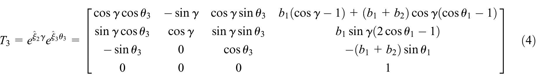
Based on the screw theory, rigid body transformation could be calculated, respectively, as follows

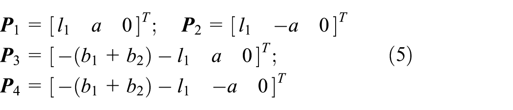
According to the structure of the chassis, the initial coordinates of the wheel center points were
Substituting equations (3)–(5) into equation (1), coordinates of the two left wheel center points could be calculated. Assumed that the contact angle between tires and ground were vertical at all times, the wheel/ground contact points were expressed as follows

Similarly, that of the two right wheel ones were

Transition between the ground coordinate and chassis coordinate
According to the plane determination of three points, three tires were in contact with the ground surface. It was assumed that
The tilting axis unit vector was
Dynamic analysis of the chassis during the tilting process
Considering that the forest chassis moves more slowly than the normal vehicle and does not have the suspension system, before the analysis of the chassis tilting dynamic model, the following simplifications and assumptions were mentioned as follows:
It was assumed that the chassis was only purely tilting (only one generalized angular velocity in the system) and without lateral sliding motion.
For the main purpose of the wheel-legged and articulated steering dynamic analysis, stiffness, friction, and damping of the tires were not considered.
Generalized coordinates of the system when the chassis is tilting
The chassis itself had six active components with 5 degrees of freedom (DOF). With the assumption above, driving direction and tilting angle were the only 2-DOF between the chassis and the ground. The generalized coordinates can be defined as

where
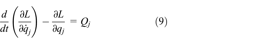
Dynamic model based on the second-kind Lagrange’s equation
Lagrange’s equation 18 is
where
Kinetic energy of the chassis during tilting
The wheel-legged chassis was a mobile parallel mechanism. Kinetic energy includes translation and rotation of rigid bodies which could be calculated as

where
Velocity of each part center consisted of three sources, and velocity could be expressed as

where


where

As a whole chassis, the angular velocity came from two aspects: articulated steering and tilting. Sketch of articulated steering is shown in Figure 3. In the chassis coordinate system, the turning radius of front wheels could be calculated as

Sketch of articulated steering.
Articulated steering angular velocity could be calculated as

Angular velocity of each part in the chassis was different. In order to calculate the rotational kinetic energy, the angular velocity should be transferred to the center of gravity coordinate of each part, which was calculated as

where
Gravitational potential energy of the chassis during tilting
According to the stability pyramid method 19 shown in Figure 4, the vector from the center of mass to the tilting axis could be calculated as

where

Stability pyramid technique model of the chassis.
Gravitational potential energy could be calculated as the internal product between the vector of gravity and

where
Generalized forces of the system
According to the principle of virtual work, the generalized force of the system could be expressed as

The external forces of the system totally came from the forces between the tires and ground and the expansion forces of the hydraulic cylinders. Substituting equations (10), (19), and (20) into equation (9), the tilting dynamic equations were achieved.
Simulation of the system through ADAMS
Establishment of the simulation
In order to verify the dynamic analysis, simulations through the dynamic software was conducted. The virtual prototype model of the four-wheel-legged chassis was established in Pro/E and imported into the ADAMS environment for the dynamic analysis. An obstacle was fixed on the ground in front of the right wheel of the harvester chassis. The initial velocity of the chassis was 5 m/s. Fiala model (a math model of wheel) 20 was chosen as the tire model of the chassis in ADAMS. Based on the product parameters, the main parameters of the tires were set as follows in ADAMS: the vertical stiffness was 1.9E+6 (N/m), and damping, rolling resistance, and CALPHA (cornering stiffness) were zero. When the harvester chassis ran on the obstacle, force generated by the collision would produce a tilting angular velocity around the tilting axis, as can be seen in Figure 5. During this process, three series of simulations were carried out.

Dynamic simulation in ADAMS environment.
The calculation of chassis dynamic tilting analysis was obtained by iterative method. As can be seen in Figure 6, initial parameters of the chassis tilting in the simulation were obtained. Δt = 0.1 s was the iterative time step of the system. Through the cyclic calculation by the dynamic equation, the tilting angular velocity of the chassis during the process was achieved.

Dynamic analysis strategy for the chassis tilting.
Result comparison between simulation and calculation
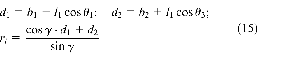
The first simulation studied the influence of the tilting side wheel-legs on tilting angular velocity. Three situations were presented in this simulation: tilting without adjustment, tilting while lifting the leg at the wheel-leg rotation angular acceleration of 60 deg/s2, and shortening the leg at the same acceleration. As can be seen in Figure 7, the average angular acceleration of the three situations in the simulation was 133.72, 146.41, and 122.5 deg/s2, respectively. That calculated results by dynamic analysis were 126.44, 136.10, and 112.10 deg/s2, respectively. The maximum tilting angles of the three situations in the simulation were −13.57°, −12.63°, and −14.84°, respectively. That calculated by dynamic analysis were −10.19°, –9.12°, and −11.55°, respectively.
Influence of the tilting side wheel-legs.
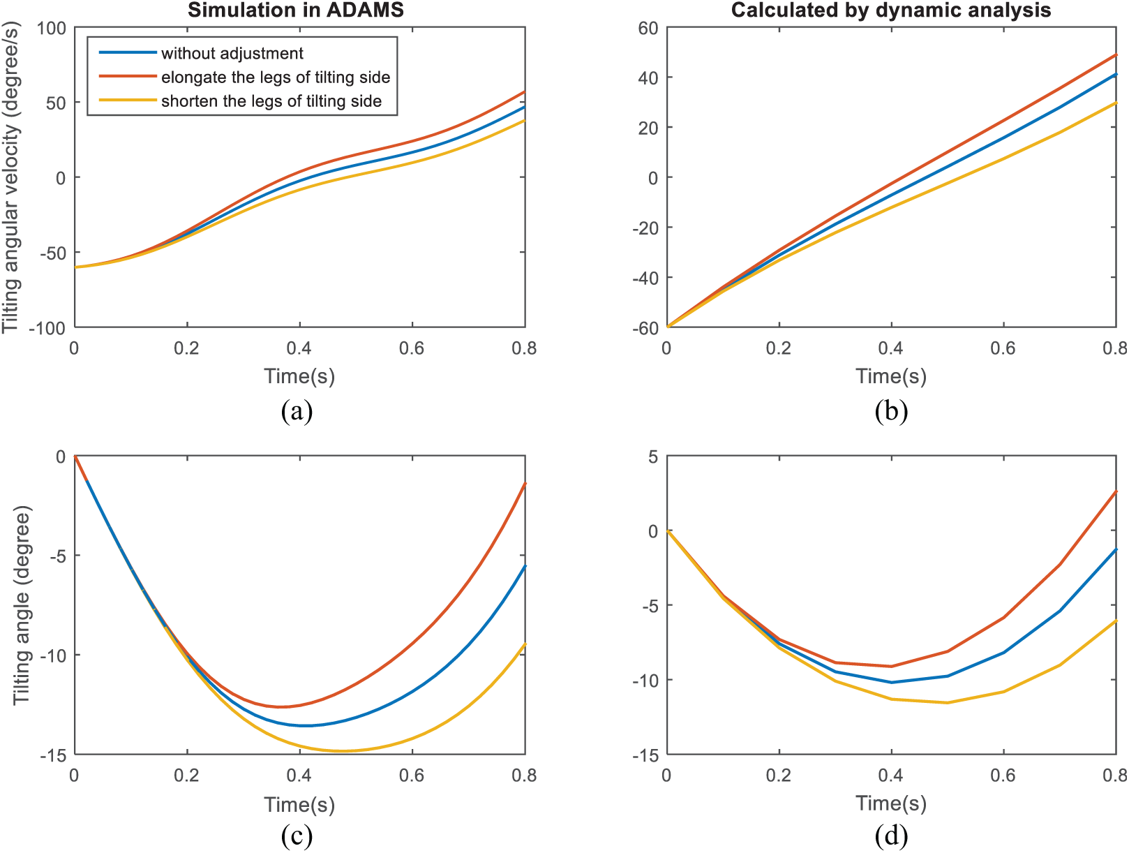
The second simulation studied the influence of the other side wheel-legs. Three situations were presented in this simulation as same as the first one. As can be seen in Figure 8, the average angular acceleration of the three situations in the simulation was 133.72, 128.97, and 136.81 deg/s2, respectively. That calculated results by dynamic analysis were 126.44, 121.35, and 130.45 deg/s2, respectively. The maximum tilting angles of the three situations in the simulation were −13.57°, −13.77°, and −13.38°, respectively. That calculated by dynamic analysis were −10.19°, −10.32°, and −10.13°, respectively.

Influence of the other side wheel-legs on tilting angular velocity.
The third simulation studied the influence of the articulated steering on tilting angular velocity. Three situations were presented in this simulation: tilting without adjustment, tilting while turning to the tilting side at the angular acceleration of 30 deg/s2 for the wheel-leg rotation, and tilting while turning off the tilting side at the same acceleration. As can be seen in Figure 9, the average angular acceleration of the three situations in the simulation was 133.72, 139.03, and 124.08 deg/s2, respectively. That calculated results by dynamic analysis were 126.44, 136.55, and 115.48 deg/s2, respectively. The maximum tilting angles of the three situations in the simulation were −13.57°, −13.32°, and −14.69°, respectively. That calculated by dynamic analysis were −10.19°, –9.44°, and −10.93°, respectively.
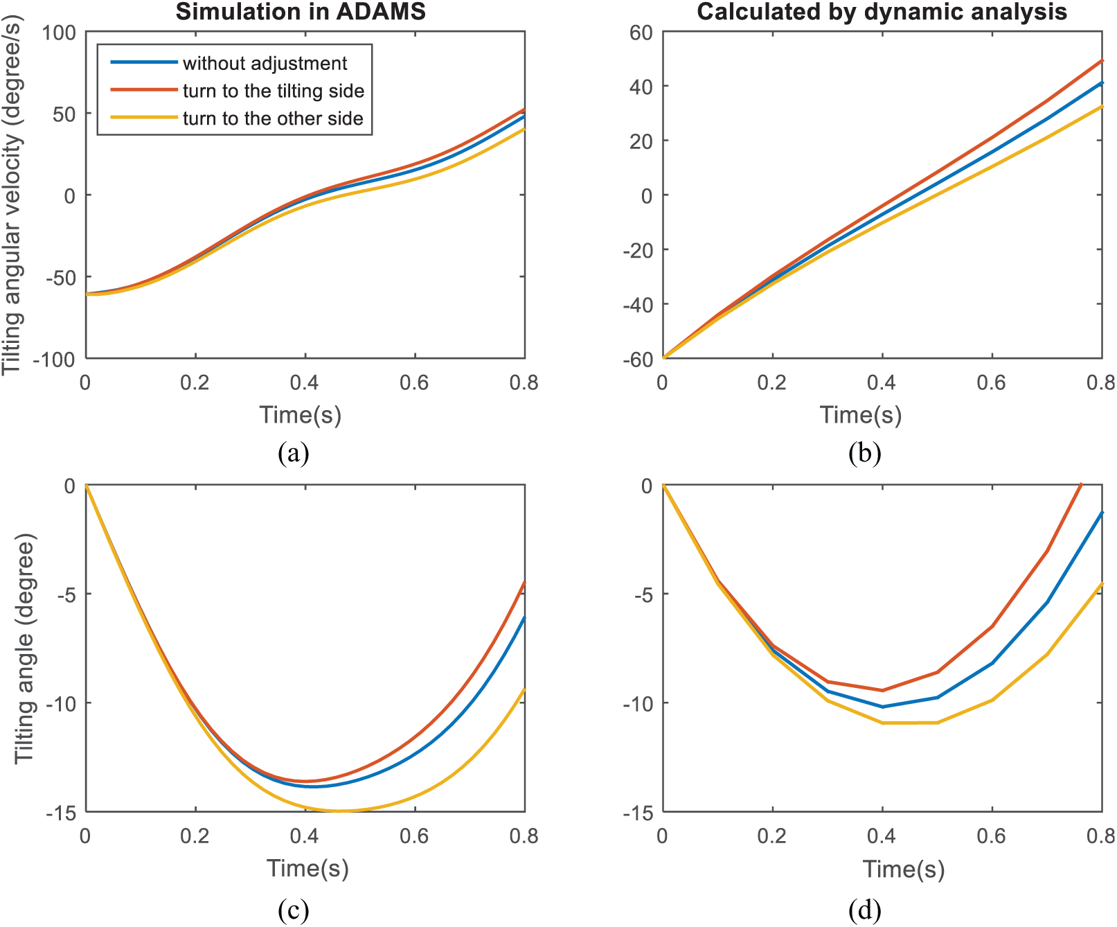
Influence of the articulated steering on tilting angular velocity.
Conclusion
The following conclusions can be drawn from this study:
Results of the simulations and calculations were highly consistent in terms of the tilting tendency influenced by the adjustments. Both simulations and calculations showed that the lifting the tilting side wheel-legs, shortening the other side legs, and turning to the tilting side could help prevent tilting of the chassis. The accuracy of the calculations was proved by the simulations.
As can be seen in Table 1, the increase and decrease rates of the angular accelerations were 9.49%, 2.31%, 3.91% and 8.39%, 3.55%, 7.21% of the three ADAMS simulations, respectively. That calculated by the dynamic equations were 7.64%, 3.17%, 8.0% and 11.34%, 4.03%, 8.67%, respectively. Average error of the change rate between simulation and calculation was 2.4%, 0.67%, and 2.75%. Through both simulation and calculation results data, the rate of the angular accelerations was higher when the tilting side wheel-legs were lifted. It was more effective to lifting the tilting side wheel-legs than shorten that of the other sides.
Compared with the simulations, the average angular accelerations were lower in the calculation. The errors might be caused by the reverse torques and frictions of the tires on the ground. That would extend angular acceleration of the chassis. The maximum tipping angles in the calculations was smaller than that in the simulations. These errors might be caused by the stiffness of tires in simulation. That would extend the tilting acceleration time of the chassis, and the initial tilting velocity would stay for a longer time in the simulation, as can be seen in Figures 7–9. For the future research, the tire model will be included in the dynamic equation for more accurate analysis.
Data analysis between simulations and calculations.

Footnotes
Acknowledgements
The authors would like to thank Huang Qingqing and Zheng Yili for their important contribution to this work.
Handling Editor: António Mendes Lopes
Declaration of conflicting interests
The author(s) declared no potential conflicts of interest with respect to the research, authorship, and/or publication of this article.
Funding
The author(s) disclosed receipt of the following financial support for the research, authorship, and/or publication of this article: This work was supported by the Fundamental Research Funds for the Central Universities (No. 2015ZCQ-GX-04), National Nature Science Foundation of China (Nos 31300596 and 31670719), and China Postdoctoral Science Foundation (No. 2014M550628).