
Abstract
Brace structures with nonlinear stiffness are attractive in vibration mitigation. A new brace consisting of a novel convex column, which is characterized by the addition of a bulge structure compared to a column with constant cross-section, is proposed as a hysteresis brace structure with great applicability for mitigation of low-frequency vibration. The negative stiffness and D-shaped hysteresis damping of the proposed convex column brace generated by the buckling mode transition are verified theoretically and numerically. Comparisons of hysteresis characteristics of the proposed convex column brace and the one with the constant cross-section column are carried out to testify the outperformances of the proposed brace. The results demonstrate that the convex column brace can provide stronger bearing capacity with a smaller deflection and realize hysteresis damping within a shorter displacement range. In addition, a full parametric study is conducted to clarify the effects of geometric properties on hysteresis behavior. The investigation performed in this study not only demonstrates the great applicability of the proposed convex column brace, but also provides guidance on brace design for mitigation in practical application.
Keywords
Introduction
Large-scale equipment with low spindle speed, such as low-speed diesel engines and pumps, are widely applied in ocean engineering field. The low-frequency responses (i.e. ≤10 Hz) generated by them have a potential of inducing structural damage and impairing the precision of instruments and personnel health. In practice, vibrations at low frequencies are difficult to mitigate. On one hand, the commonly used steel braces show poor effects on mitigating low-frequency vibrations, as mitigation is only achieved when the excitation frequency is larger than
In recent years, nonlinear isolators have drawn increasing attention since they possess the advantage of mitigation effectiveness compared with the linear ones.3–5 The characteristics of many different kinds of nonlinear isolators in recent years have been summarized by Ibrahim, 6 in which a group of isolators that utilize the nonlinear stiffness mechanism to lower their natural frequencies have been confirmed in mitigations of low-frequency vibrations. Zhang et al., 7 Carrella et al.,8,9 and Le and Ahn 10 investigated a novel combined positive and negative stiffness isolator (CPNSI) to mitigate wide-band vibrations. The CPNSI, which consists of a vertical spring and two negative stiffness elements of symmetric horizontal compression springs, shows a nonlinear characteristic in stiffness. Then the excellent performance of this isolator on mitigating low-frequency vibrations is confirmed by a series of experiments. Tian et al. 11 and Yang et al. 12 developed an isolation system utilizing CPNSI for mitigating vibration of moving vehicles.
Afterwards, several investigations demonstrated that the buckled columns could also work as a negative stiffness element to lower the stiffness of an isolator. Liu et al. 13 and Huang et al. 14 proposed a new CPNSI using buckled columns as the negative stiffness structure instead of two symmetric horizontal compression springs. The stiffness and dynamic characteristics are investigated both theoretically and experimentally. Virgin et al. 15 developed a vertically oscillating base made of a highly deformed slender beam, which can be clamped together, forming a loop. The results show that buckled columns can provide a large negative stiffness through complex jump at a small displacement. In addition, Bonello et al. 16 and Fulcher et al. 17 designed a tuned vibration isolator consisting of two vertical buckled beams. Through the control of buckling shapes with different boundary conditions, the stiffness of buckled beams can be adjusted, and hence the isolator can be tunable toward the target frequency range. However, this type of isolator cannot satisfy the requirement of strong bearing capacity.
Based on the mechanism that the stiffness of a column can be changed by its buckling mode, a new brace structure using a constant cross-section column was proposed. The brace could provide high stiffness in equilibrium, achieving negative stiffness under the critical load through the boundary conditions of column ends changing from fixed mode to pinned mode. In a loading–unloading process, a flag-shaped hysteresis loop, the area of which represents the energy dissipation in a period, is shown in the axial force–displacement relationship. First, Kalathur et al. 18 investigate the buckling behavior of a constant cross-section column loaded by unattached flat platens theoretically and experimentally. Then Lakes and colleagues19–21 proposed column braces made from polymethyl methacrylate (PMMA) and stainless steel, respectively. The outperformances of the excellent braces on both high stiffness and hysteresis damping can hardly be attained by the currently used ones. Furthermore, the application of this mechanism was extended to the seismic design in architectural engineering. Wu and Phillips 22 designed a sophisticated capped column made of shape memory alloy (SMA) with constant cross-section configuration, possessing the elastic buckling mode jump (BMJ) mechanism. The hysteresis behavior and the effects of geometric properties are investigated through a verified theoretical model and a parametric study. A brace system utilizing capped columns with multiple dimensions is designed. The responses of a three-story frame are compared among the cases of the proposed BMJ system, buckling-restrained brace frame (BRBF) system, and conventional brace frame (CBF) system. The self-centering feature and outperformance of the BMJ system in residual drift ratio compared to the other two cases make it best suited to mitigate further damage to the structure. Although the outstanding mitigation effectiveness of the braces demonstrates the great application value of columns, investigations on its hysteresis behavior are not comprehensive enough and their applicability still needs to be upgraded.
The configuration of the column should be improved to moderate the excessive stress problem coming along with the reduced slenderness ratio. Several hysteresis characteristics that are important for brace design, such as the bending deflection, the axial displacement range of hysteresis loop, and the effect of frequency on dynamic response, have not been analyzed. In terms of the parametric study, the effects of parameters on the differences of axial forces and displacements of the post-primary-buckling and post-secondary-buckling phases, which are closely related to obtaining hysteresis dissipation under compression, are also required before practical applications.
In this article, a convex column brace is proposed and investigated to mitigate low-frequency vibration by obtaining hysteresis damping. The hysteresis behavior and the negative stiffness of the proposed brace are preliminarily verified through both the theoretical model and numerical simulations. Then, numerical simulations of the brace with a convex column and one with the constant cross-section column are performed for detailing the hysteresis characteristics. The results verify the outperformances of the convex column on hysteresis characteristics of the bearing capacity, bending deflection, and hysteresis displacement range. In addition, a full parametric study is carried out to clarify the influence of related geometric parameters on each characteristic, as guidance for brace design. The results demonstrate that the slenderness of a column should be determined first as it has a significant impact on each characteristic. The bulge thickness, depth ratio, and end thickness ratio can be adjusted for fine-tuning of certain characteristics.
Hysteresis behavior of the convex column brace
Description of the convex column
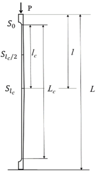
Unlike the configuration of the constant cross-section column,19–22 the studied convex column in this article consists of a special column structure and two thick ends. The schematic configuration of a convex column is shown in Figure 1(a). The structure of the convex column can be regarded as a constant cross-section column with a bulge structure at one side. The value of
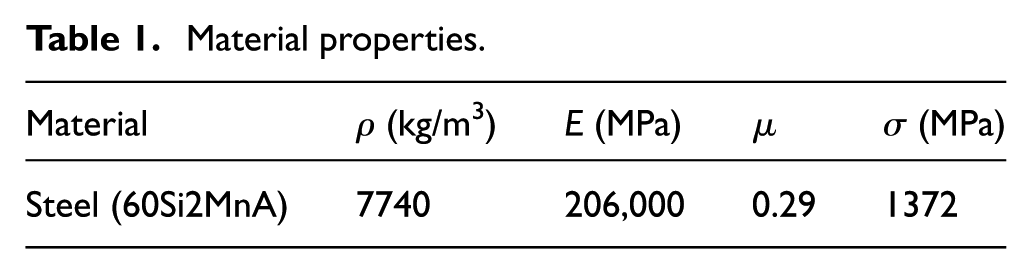
Material properties.

(a) Schematic configuration of a convex column, (b) a multiple-column brace, and (c) a mixed brace.
Two damping braces utilizing convex columns are shown in Figure 1(b) and (c): a multiple-column brace and a mixed brace consisting of columns and high-stiffness springs. Both braces are equipped under the bottom of the equipment for mitigating the vertical vibrations transmitted to structures. The multiple-column brace can be used in parallel with other brace or dampers to increase the local stiffness and mitigate displacement responses. In terms of mixed brace, several of them can be arranged in an array to support and mitigate an equipment. Through adjusting the number of braces and columns, configuration of eccentric columns, and the stiffness of springs, the brace array can provide high bearing capacity for an equipment of large scale and mitigate low-frequency vibration effectively.
Column ends are assigned as nonsliding to avoid axial misalignment and structural distortion when compressed. As mentioned in Dong and Lakes, 19 the negative stiffness and hysteresis loop of constant cross-section columns are attributed to nonlinear deformation and the boundary condition transition of ends under harmonic axial compressions. The convex columns demonstrate buckling behavior under compression as shown in Figure 2(a). The contact mode of column ends transforms from surface-to-surface to edge-to-surface, which can also be regarded as transforming from fixed and pinned due to the same constraint feature. The energy dissipation in a loading–unloading process is calculated based on the area of the D-shaped hysteresis loop as presented in Figure 2(b).
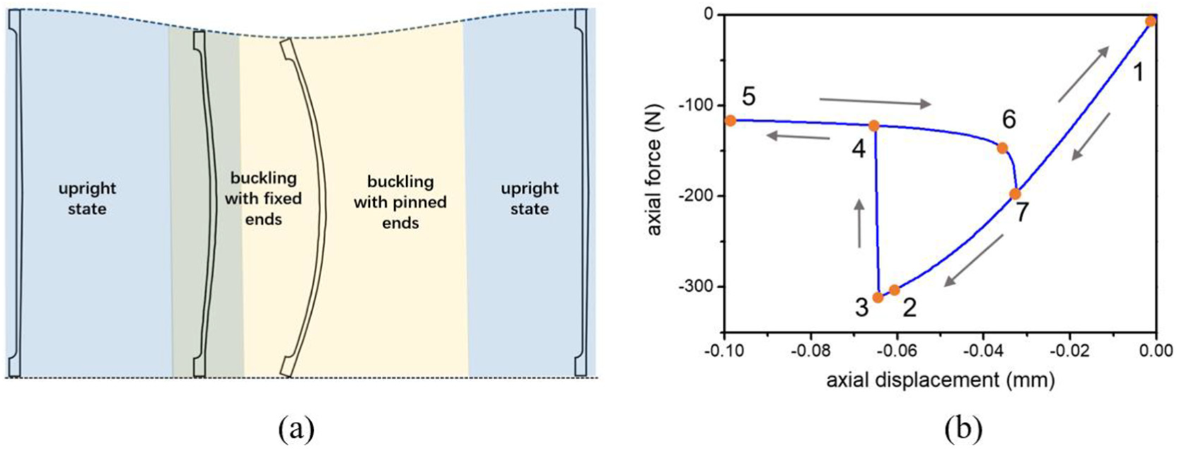
Hysteresis behavior of a convex column brace: (a) the transition of buckling modes in a cycle and (b) axial force–displacement relationship.
The theoretical model of a convex eccentric column is derived in the next section. According to the buckling behavior and the axial force–displacement relationship of a convex column, the hysteresis loop can be summarized in five phases according to Figure 2(b) as follows:
Phase a(1-2)—linear phase, remaining in the upright state;
Phase b(2-3)—post-primary-buckling phase, buckling with fixed ends;
Phase c(3-4)—transition phase;
Phase d(4-5-6)—post-secondary-buckling phase, buckling with pinned ends;
Phase e(6-7-1)—transition backward to the linear phase.
The theoretical model of the hysteresis behavior
To clarify the hysteresis behavior of a convex column, a theoretical model is derived according to the five buckling phases in a loading–unloading process listed in section “Description of the convex column.”
Phase a(1-2)—linear phase.
In this phase, an axial harmonic compressive force

where
Linear phase.
As the axial force increases to the first critical load
2. Phase b(2-3)—post-primary-buckling phase.
For a constant cross-section column, the critical load

where
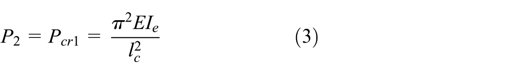
The accurate value of
The deflection function of this buckling mode with fixed ends
23
is

3. Phase c(3-4)—the transition process from buckling with fixed ends to pinned ends.
This phase is a short unstable process from post-primary-buckling to post-secondary-buckling mode. As the axial force reaches

where

The critical displacement

4. Phase d(4-5-6)—post-secondary-buckling phase, buckling with two ends pinned.
The boundary conditions of both ends change to pinned totally at Point 4 as shown in Figure 5. In this phase, the flexural stiffness provides the bearing capacity instead of its axial stiffness. The essential difference between these two modes is whether the ends of the column participate in the buckling.
The critical axial force

where
In this phase, the deflection function
23
is

Since the axial force of a column remains unchanged in a buckling mode, the axial force during the entire Phase
5. Phase e(6-7-1)—the transition process backward to the linear phase.
This phase is corresponding to Phase

Buckling mode with fixed ends.

Buckling mode with pinned ends.
Numerical simulation
In this section, the numerical simulations based on a three-dimensional (3D) brace model with a single convex column are conducted to verify the hysteresis behavior and negative stiffness of the brace. Besides, three example columns of different geometric properties are analyzed to verify the theoretical model described in section “Hysteresis behavior of the convex column brace.”
Verification of numerical simulation
Before performing the numerical simulation analysis, its accuracy is verified by comparing the simulation results of two sample columns to the experimental results in Dong and Lakes.19,20 Hysteresis loops of a stainless steel column 19 (L = 184 mm, diameter = 3.175 mm) and a polycarbonate column 20 (L = 60 mm, diameter = 3.18 mm) are obtained by simulations under the same compressions in experiments, 1 Hz displacement control of 0.057 mm and 0.5 Hz displacement control of 0.0226 mm. The established models and settings using the finite element program ABAQUS 6.14 are explained in section “The numerical model.” Note that the viscoelasticity of polycarbonate is ignored due to the lack of material information. The axial force–displacement relationships of two columns are shown in Figure 6.

Axial force–displacement relationships of two sample columns: (a) the polycarbonate column (L = 184 mm, diameter = 3.175 mm) and (b) the stainless steel column (L = 184 mm, diameter = 3.175 mm).
By comparing the simulation and experimental results in Figure 6(a), it is demonstrated that the shape of the hysteresis loop under one cycle is slightly more slender than that obtained by experiment, due to the lack of defining viscoelasticity of polycarbonate in the simulation. Although two loops cannot be completely matched, the simulation results can still reflect the hysteresis behavior. In terms of the stainless steel column, except a small discrepancy of the trigger point caused by time increment, Figure 6(b) demonstrates a good agreement between two loops. As a result, a good consistency between the simulation and experimental results can validate the feasibility and accuracy of the simulation.
The numerical model
A 3D brace model of a single convex column is established using the finite element program ABAQUS 6.14. As shown in Figure 7, the brace model consists of two identical base plates and an example column. For simulating the behavior of the example column when subjected to an axial compression, the boundary condition of the lower base plate is fixed and that of the upper one is only moveable in the axial direction. Two end flats and the contacted plate surfaces are modeled as roughly contact surfaces.

The brace model of a single convex column.
Displacement control is applied to the upper base plate instead of concentrated force for avoiding failure due to the stiffness drop in the post-secondary-buckling mode. A harmonic displacement control is assigned to the center of upper base plates, and implicit dynamic analysis is adopted to obtain the time-domain curves of axial force and displacement and the buckling behavior of the brace model.
Both plates are square, the size of which is 30 mm × 30 mm × 5 mm. They are made from the same material as the column. An example column is analyzed to verify the hysteresis behavior of the proposed brace and the geometric properties of the example column are listed in Table 2.
Geometric properties of the example column.

The column and the two base plates are modeled as 3D parts with the base feature of “solid,” and hexahedral elements are applied to mesh all of them. The element type of 8-node linear brick with reduced integration (C3D8R) is used for capturing the buckling behavior, axial force, and displacement as it is good at deformation analysis. Since only the column is deformed in the simulation, a convergence study of column mesh is performed in advance. The mesh size of the base plate is 5 mm, and that of Column 1 is set at 0.26 mm, as the convergence study demonstrates that the difference rate of the maximum axial force is dropped down to 0.5% when the mesh size decreases to 0.26 mm. Material damping ratio (0.004) is converted to Rayleigh damping and adopted in the implicit dynamic simulation. A cosine curve of displacement control with the peak-to-peak amplitude of 0.1 mm and the frequency of 2.5 Hz is assigned to the center of the upper base plates, and the hysteresis behavior is analyzed by implicit dynamic analysis.
Hysteresis behavior simulation
The hysteresis behavior in a cycle is well captured. The buckling modes in post-primary-buckling and post-secondary-buckling phases are shown in Figure 8. In order to show the buckling modes more clearly, buckling deflections are magnified fivefold, and the separations of ends and base plates are represented in the zoom-in window. Time-domain curves of the axial force and displacement of the brace model from the simulation are shown in Figure 9(a). Two leaps of axial force as shown in dotted boxes correspond to Phases
Buckling modes of the example convex column (with fivefold magnified deflection): (a) post-primary-buckling phase and (b) post-secondary-buckling phase.
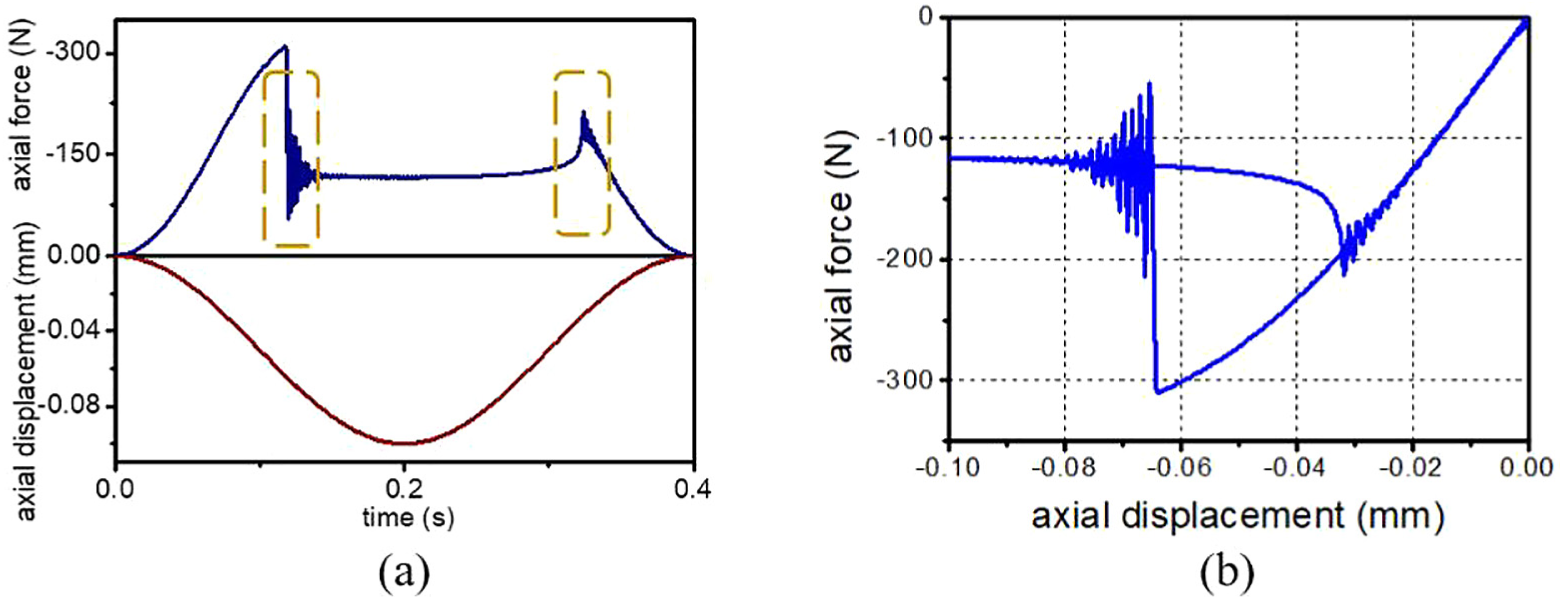
Hysteresis curves of the brace model: (a) time-domain curves of axial force and displacement and (b) axial force–displacement relationship.
The negative stiffness is generated by the contact mode transition from the surface-to-surface to the edge-to-surface mode and backward. Then the corresponding drastic reduction in the contact area leads to a decrease in the bending stiffness of the convex column in loading, and the restoration of bending stiffness is conducted with the increase of contact area when unloading.
24
Two transitions in Phases
As shown in Figure 9(b), the hysteresis behavior of the brace model is triggered and attenuated at the displacement of –0.064 and –0.032 mm. It demonstrates that the hysteresis damping works only when the axial displacement range of compression exceeds the range between the trigger and the attenuation point. The extreme buckling stress of the column under the displacement control of 0.1 mm is 265.7 MPa. However, as the stress increases with the buckling deflection, yielding will arise when the ultimate stress is reached. For this brace model, the maximum working displacement should be limited to the yielding point displacement of the example column, –9.5 mm.
Comparison with the theoretical results
To verify the theoretical model described in section “Hysteresis behavior of the convex column brace” and estimate the influence of geometric parameters on hysteresis characteristics preliminarily, the simulation and theoretical results of the example column and the two derivative ones are analyzed. The geometric properties of the three columns are listed in Table 3. The example column analyzed in section “Verification of numerical simulation” is named Column 1 and the other two are named Columns 2 and 3. Column 2 is characterized by shrunken bulge thickness ratio
Geometric properties of Columns 1–3.

Comparisons between the theoretical and simulation results of Columns 1–3 are displayed in Figure 10. Axial force–displacement relationships of Column 1 and the other two derivative columns are shown separately to present the results more clearly. The displacement control amplitudes of the three columns are enlarged to 0.12 mm as the hysteresis displacement range of Column 3 moves downward.

Hysteresis loops of Columns 1–3: Column 1 (energy dissipation: 3 N mm; extreme stress: 242 MPa); Column 2 (energy dissipation: 1.5 N mm; extreme stress: 172.6 MPa); and Column 3 (energy dissipation: 8 N mm; extreme stress: 334.6 MPa).
Good agreements between the theoretical and simulation results of the three columns are shown in Figure 10. Nevertheless, the positions of Points 2 and 6 obtained by the theoretical model and simulations are discrepant. Such discrepancy is likely due to the not considering stiffness variations in the post-secondary-buckling phase. Besides, another discrepancy is the undulation behaviors caused by two transitions of boundary condition. Although the undulation behaviors are unpredictable and the transition processes from Point 6 to 7 are not as sharp as the theoretical results, the good agreements between the simulation and theoretical results of most critical points still verify the theoretical model.
Three hysteresis loops in Figure 10 demonstrate that minor modifications of geometric properties could induce significant variations of the hysteresis characteristics, such as axial forces, hysteresis displacement range, and energy dissipation. Hence, the investigations of the hysteresis characteristics and the effects of geometric properties on them are obliged.
Analysis of the hysteresis characteristics of the convex column brace
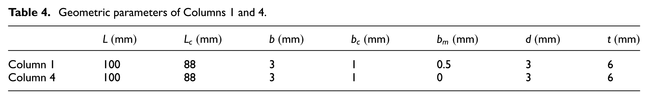
The results in the last section demonstrate that the hysteresis behavior of a column brace ascertains its sphere of application in practice. In this section, the hysteresis characteristics, such as axial force, axial displacement, and energy dissipation, of the new brace are investigated numerically. In addition, the advantages of the proposed brace are revealed through the comparison between the results of the brace models with a convex eccentric column (Column 1) and a constant cross-section one (Column 4), respectively. As listed in Table 4, the contrast column is only characterized by the absence of the convex structure compared to Column 1. The bearing capacity, axial displacement, energy dissipation, buckling stress, as well as the effect of compression frequency on them are analyzed in the following sections.
Geometric parameters of Columns 1 and 4.
Bearing capacity
The bearing capacity values of a column in post-primary-buckling and post-secondary-buckling phases are significant hysteresis characteristics in brace design. Axial forces of Points 3
Axial forces of Columns 1 and 4.


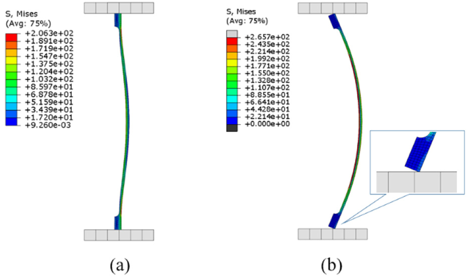
Comparison of Columns 1 and 4: (a) the axial force–displacement relationships (with axial forces marked) and (b) the buckling shapes (with fivefold magnified deflection) and the extreme buckling stresses of two braces at a displacement of 0.1 mm.
Figure 11(a) and Table 5 demonstrate that both
Compared to the column with constant cross-section, the convex column brace can provide a stronger bearing capacity in both buckling modes and possesses a small deflection and weakly increased extreme buckling stress under the same displacement control.
Axial displacement range and energy dissipation
Similar to the axial force, the axial displacement range of hysteresis behavior is also a factor that must be considered in the brace design, especially for the situation when the brace and springs are arranged in parallel for supporting large-scale equipment. The axial force–displacement relationship (with axial displacements marked) is shown in Figure 12.

Axial force–displacement relationship of braces with Columns 1 and 4 (with axial displacements marked).
As shown in Figure 12, the hysteresis loop of Column 1 moves to the lower left position of Column 4. In terms of Phase
Energy dissipation of a column represents the mitigation effectiveness of a brace. As mentioned in section “The numerical model,” energy dissipation of a column is calculated based on the area of the hysteresis loop. Therefore, the positions of Points 2, 3, 4, and 7 in Figure 12 are the key points for evaluating the energy dissipation, where the maximum differences between axial force and displacement in a loop are the most intuitive factors. The energy dissipations of brace models with Columns 1 and 4 are 3 and 3.15 N mm, respectively, which demonstrates that the shape variation of the hysteresis loop generated by the bulge structure slightly declines the energy dissipation by 0.15 N mm.
Although the convex column possesses a weak disadvantage in terms of energy dissipation, both shortened hysteresis displacement range and undulation behavior still confirm the greater applicability of the convex column.
Buckling stress
When a column brace is pressed to the yielding point, its bearing capacity is invalid. Clarifying axial deformation of the column at the yielding point is quite crucial for avoiding yielding in practical applications. To analyze the deformed shapes of two brace models, displacement control with an amplitude of 30 mm is applied to capture the axial deformation when extreme buckling stress reaches the ultimate stress. The deformed shapes of the two columns when the yielding point is reached are obtained as shown in Figure 13.

Buckling shapes of two braces at the yielding point (without amplification).
The axial deformation of Columns 1 and 4 are –9.5 and –11.24 mm, respectively. As shown in Figure 13, the high stressed zone (in dashed box) of Column 4 is located around the middle section. Nevertheless, the zone of Column 1 is separated into two parts as the cross-sectional area decreases from the middle section toward both ends gradually. As a result, the deformed shape of Column 1 changes as the deformed section is shifted up or down. As for whether the deformation section is moving up or down, the subtle difference between buckling shapes of the two parts caused by undulation behavior is the decisive factor.
The extreme stress of the deformed section is calculated by dividing the maximum bending moment by the section modulus in bending. Compared to Column 4, the section modulus in bending of Column 1 is increased 1.8 times and the value of
Effect of compression frequency on the hysteresis behavior
To verify the hysteresis behavior under compressions in the range of 5–10 Hz and analyze the effect of frequency on it, simulations with displacement control at 5, 7.5, and 10 Hz are carried out based on the same brace model in this section. The simulation results are shown in Figure 14.

Axial force–displacement relationships of two brace models under compressions at 2.5, 5, 7.5, and 10 Hz.
As shown in Figure 14, the hysteresis behaviors of the two brace models are all triggered under displacement control of 5, 7.5, and 10 Hz; hence, the hysteresis loops preliminarily verify the feasibility of Columns 1 and 4 under compressions from 0 to 10 Hz. Compression frequency ranging from 0 to 10 Hz shows a little effect on the hysteresis loop as four key points remain in the same positions in the axial force–displacement curves. However, the undulation in axial force of both braces is more intense during the whole hysteresis loops as the loading frequency increases, leading to consequent variations of energy dissipation and undulation behavior in Phase

The displacement range of the undulation behavior and the energy dissipation of two brace models.
The stability of Column 4 in Phase
The line chart in Figure 15 shows that the small-amplitude undulation of axial force in Phase
The parametric study
As mentioned in section “Hysteresis behavior simulation,” the hysteresis behavior of a convex column can be controlled by its geometric properties. Hence, a set of appropriate geometric parameters is the key to ensure the triggering of hysteresis behavior when designing a brace. To clarify the influence of the relevant geometric properties on hysteresis characteristics, a full parametric study is carried out in this section.
For a convex column, the positions of Points 3, 4, 6, and 7 in Figure 2(b) are basic assessments of the hysteresis behavior, in which Points 3 and 7 are considered as the hysteresis behavior trigger and attenuation point. Therefore, hysteresis behavior is achieved only when the axial force and displacement ranges can cover these points simultaneously. First, the axial forces of Points 3 and 4 (
According to the theoretical model described in section “Hysteresis behavior of the convex column brace,” hysteresis characteristics are directly related to several geometric parameters:
Bulge thickness ratio
The influence of the bulge structure with certain configurations on hysteresis behavior has been investigated in section “Numerical simulation,” and the results demonstrate that the hysteresis loop tends to be slender due to the alterations of axial forces and displacements. As the property is associated to areas of cross-sections directly, the bulge thickness ratio shows definite impact on each index as shown in Figure 16.

Effect of bugle thickness ratio on indices.
As shown in Figure 16, the values of

Hysteresis loops of columns with the bulge thickness ratios of 0.2, 0.5, and 0.8.

Deformed shapes of columns with the bulge thickness ratios of 0.2, 0.5, and 0.8.
As shown in Figure 17,
The value of the bulge thickness ratio should be ascertained based on the requirements of bearing capacity and axial displacement range, as, by increasing the bulge thickness ratio, the bearing capacity of the brace in both buckling modes can be strengthened and the axial displacement range can be shortened. However, an excessive bulge thickness ratio is not recommended to avoid yielding.
Slenderness
The effects of slenderness

Effect of slenderness on indices.
Overall, each curve in Figure 19 shows a strong nonlinear relationship with slenderness. As
Depth ratio
In this section, the value of

Effect of depth on indices.
As shown in Figure 20, both
End thickness ratio
In this section, the height

Effect of the end thickness ratio on indices.
On one hand, due to the enlargement of
Summary of the parametric study
Through the parametric study, the effects of geometric properties on indices are analyzed, and the ranking of their effects on each index is listed in Table 6. Slenderness is the most significant property as it has huge effects on all indices, and the bulge thickness ratio and depth ratio follow behind it as their distinct effects on two indices, respectively.
Ranking of the influences of geometric properties on each index.

Overall, when designing a convex column brace, slenderness should be given priority for its huge effects on most indices. Several parameters can be considered secondarily in the fine adjustment of hysteresis characteristics. Depth and bulge thickness ratio can be adjusted for axial forces, and changing the bulge thickness is also helpful for alerting the hysteresis behavior trigger point, attenuation point, and yielding deformation. Depth can also be adjusted for increasing energy dissipation.
Conclusion
In this article, a convex column brace is proposed and its hysteresis behavior generated by buckling mode transition is investigated. The major conclusions are summarized as follows:
The hysteresis behavior and negative stiffness of the proposed brace are verified both theoretically and numerically. A D-shaped hysteresis damping is achieved by allowing the boundary conditions of both ends to change from fixed to pinned under compression. The results not only demonstrate that the hysteresis characteristics of a convex column brace are essential for hysteresis behavior triggering in practical applications, but also verify the effects of geometric properties on hysteresis characteristics preliminarily.
Comparisons of the hysteresis characteristics of the convex column brace model and the one with the constant cross-section column show that the proposed brace can provide higher bearing capacity with smaller deflection and realize hysteresis damping within a shorter displacement range.
The parametric study clarifies how the geometric properties affect the hysteresis behavior and provide guidance for brace design. The results demonstrate that the slenderness of a convex column should be confirmed first due to its huge effects on all indices. Both the bulge thickness ratio and depth ratio can be altered for improving the bearing capacity, and changing the bulge thickness ratio can also be considered when adjusting the axial displacement and bending deflection.
As the hysteresis behavior of the proposed brace triggered in compression leads to the lack of stiffness, an integral convex column brace system, which consists of both convex columns and positive stiffness elements, will be designed and optimized in future research.
Footnotes
Handling Editor: Yunn-Lin Hwang
Declaration of conflicting interests
The author(s) declared no potential conflicts of interest with respect to the research, authorship, and/or publication of this article.
Funding
The author(s) disclosed receipt of the following financial support for the research, authorship, and/or publication of this article: This work was supported by the National Science Fund for Distinguished Young Scholars (51625902), the Taishan Scholars Program of Shandong Province (TS201511016), and the Innovation Program (2016) approved by the Ministry of Industry and Information Technology of P.R. China.