
Abstract
This article presents a high precise deployment mechanism for a deployable space telescope to facilitate satellite miniaturization. It is designed with a passive deployment mechanism utilizing a spring hinge. In particular, the customized modules and an assembly jig are specifically designed to reduce alignment errors. To confirm the feasibility of the designed mechanism, three alignment errors that influence the optical performance of the structure—tilt, de-center, and de-space—are theoretically analyzed for quarter, half, and full model, respectively. In the case of quarter model, significant results are obtained as a tilt of 21.12 µrad, a de-center of 2.20 µm, and a de-space of 1.71 µm. Based on the theoretical analysis, a deployment mechanism of the quarter model is fabricated, and the alignments of the deployment mechanism are experimentally investigated with a measurement platform consisting of five non-contact-based laser displacement sensors. In addition, the influence of gravity on the alignment error is analyzed and compensated by investigating the tendency of the alignment error according to the rotation degree of the measurement model for the direction of gravity. As a result of the gravity compensation, the proposed mechanism gives acceptable alignment errors as a tilt of 30.04 µrad, de-center of 8.92 µm, and de-space of 4.03 µm, which are controllable by employing the conventional focusing mechanism.
Keywords
Introduction
Deployment mechanisms remain in a stowed state during the launching process and deploy when the satellite reaches its target orbit. Research on these mechanisms has focused on minimizing satellite payload volumes.1,2 Conventionally, deployment mechanisms have been applied to solar panels and antenna.3,4 Representatively, a deployable antenna using the cable-net tension structure controlled by hinges 5 and cables and a large ring deployable mechanism using multiple deployable modules of six-bar linkage controlled by the cables 6 were presented and studied. These structures can maximize the storage efficiency of a launch vehicle, enabling the launch of multiple satellites. Likewise, deployment mechanism applications have been extended to deployable optical structure (i.e. deployable space telescope). 2 At present, high-resolution satellite data are captured by Earth Observation (EO) systems such as GeoEye, QuickBird, and WorldView.7,8 Since those satellites employ the fixed optical structure, they are large, heavy, and consequently very expensive to construct and launch. By employing deployable optical structure, therefore, we may dramatically reduce the launch costs for those EO systems and it will ultimately result in a much lower cost per image. Apart from EO system, space telescope to observe deep space such as Hubble telescope also employs deployable structure for higher performance as well as storage efficiency of a launch vehicle. Representatively, National Aeronautics & Space Administration (NASA) is developing the deployable telescope called James Webb Space Telescope (JWST) which is the scientific successor to Hubble, which will launch in 2021.9,10 The secondary mirror is deployed using high-strain composite hinges considering positional accuracy, and deployable primary mirror can secure 6.25 times more collecting area than Hubble. 11 On the contrary, the following research projects for the small satellite have attempted to integrate deployment mechanisms for optical structures: NASA’s Nuclear Spectroscopic Telescope Array (NuSTAR), 12 the Beijing University of Aeronautics and Astronautics–Satellite (BUAA-Sat), 13 the Technical University of Berlin’s Dobson Space Telescope (DST), 14 the Pico-satellite for Remote-sensing and Innovative Space Missions (PRISM), 15 and Utah State University of deployable optics for CubeSat. 16 In particular, the DST and PRISM projects have demonstrated innovative designs for small satellites. However, PRISM is limited to very rough resolution (30 m), and DST is still under construction. More recently, Delft University of Technology started working on a deployable synthetic aperture telescope in 2014 and is now continuing the research in cooperation with The European Space Agency, The Netherlands Organisation for Applied Scientific Research, and Astrophysics Data System.8,17 The deployable aperture telescope consists of a three-linkage set with motor and deploys the secondary mirror and primary mirror segments sequentially.
In the previous study, we presented a simple deployable mechanism and confirmed the alignment errors using the six-axis touch probing–based measurement device. 18 However, the reported alignment errors were too large to apply in deployable space telescope even with additional focusing mechanism. In this article, therefore, we design, fabricate, and evaluate a high precise deployment mechanism for a Cassegrain-type deployable space telescope to realize 1-m ground resolution.19,20 In order to minimize alignment error, an assembly jig for the connecting linkage module is specifically designed, and the alignment error of the mechanism is simulated. Based on the simulation results, the design of the deployment mechanism is finalized and fabricated. Then, to evaluate the alignment error of the mechanism and to compensate for the gravity effect, a three-dimensional measurement platform with five laser displacement sensors is constructed. In the constructed measurement system, the alignment of the deployable optical mechanism is experimentally investigated according to the rotation degree of the measurement platform. Finally, the gravity-compensated alignment error is presented based on the tendency of the alignment error according to the rotation degree of the deployable optical structure.
Design of deployment mechanism
Deployment mechanisms generally work via the relative motions of the mechanism components. Therefore, appropriate joint clearance exists to allow for relative motion. This joint clearance results in the nonlinear behavior of components. 21 This causes alignment errors in the deployment mechanism. In the deployable optical structure, alignment errors are classified into tilt, de-center, and de-space errors, as shown in Figure 1. Tilt refers to the degree (τ) between the reference axes of the secondary mirror and the primary mirror. De-center is the distance (Δ) between the central axis of the ideal and the actual secondary mirrors. De-space is the difference (s) between the ideal and actual distances between the primary and secondary mirrors. 23

Definition of de-space, tilt, and de-center for mirrors. 22
Before we design the deployment mechanism, the design requirements of a deployment mechanism capable of achieving 1-m ground resolution are established with reference to KOMPSAT-3 from the Republic of Korea. 20 Table 1 shows these requirements.
Requirements for KOMPSAT-3.

As shown in Figure 2, the proposed deployment mechanism consists of upper and lower panels on which the secondary and primary mirrors are installed: eight customized linkages connecting the two panels, four spring hinges that drive the mechanism, and eight supporting modules preventing linkage twisting. In Figure 3, the working principle of the proposed deployment mechanism is presented. In the stowed state, the restoring force of the spring hinge was suppressed by the separating device. When the separating device was released for deployment, the linkages were deployed by the restoring force of the four spring hinges. When deployment was completed, the linkage was positioned upright at 90°.

Deployment mechanism configuration.
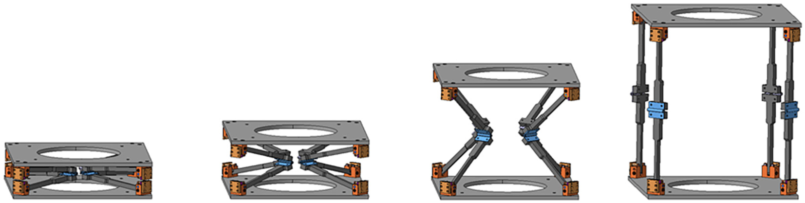
Working principle of the proposed deployment mechanism.
Figure 4 shows customized apparatus to minimize the alignment errors. The male and female cone shapes on the linkages are employed to prevent linkage twisting. When assembling the connecting linkage module using the assembly jig, the cone shapes will help prevent the x- and y-axis tilt and de-center of the x–y plane. The four ball plungers on the lower section of the supporting module are installed to reduce the x-axis tilt and de-center errors. In addition, a latching device is installed on the lower section of the supporting module to mitigate the impact caused by deployment and to reduce x- and y-axis tilt and de-center. Ultimately, a significant reduction in alignment errors can be expected for the deployable optical structure employing the proposed components. In addition, to precisely assemble a spring hinge and two linkages, the assembly jig for the connecting linkage module in Figure 5 is designed to reduce the de-space, de-center, and tilt alignment errors.
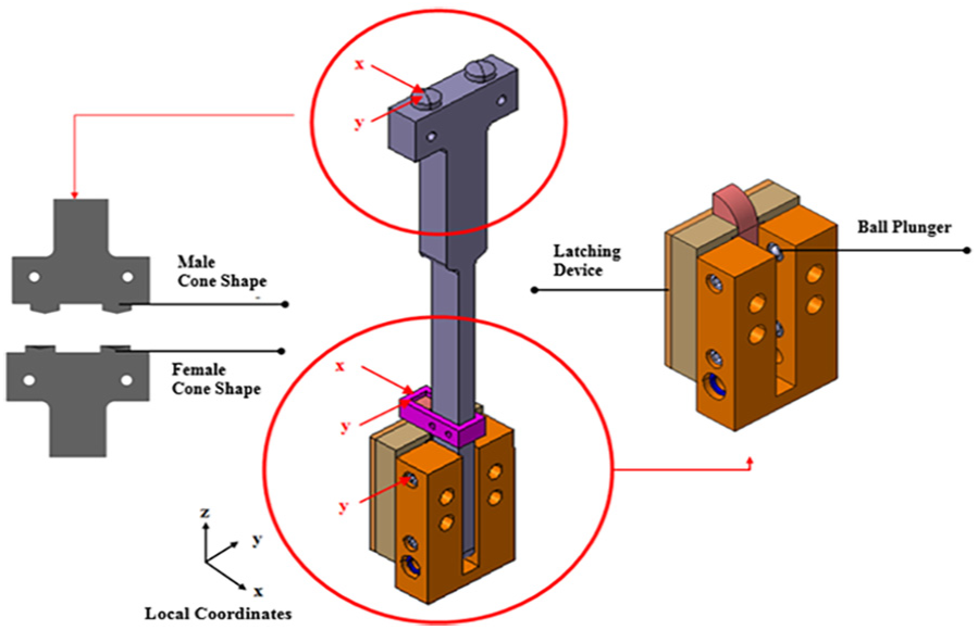
Customized linkage and supporting module.

Assembly jig for connecting linkage module.
Numerical simulations
The proposed deployable optical structure consists of various components, including linkages, joints, spring hinges, latching devices, ball plungers, and bearings. Because the components are assembled with some clearance, alignment errors occur when the deployment mechanism operates. This clearance between components may contribute to the three types of alignment error (tilt, de-center, and de-space) in the mechanism. Therefore, the overall alignment error of the proposed mechanism caused by the assembly of components is investigated through a theoretical analysis.
Assumptions for theoretical alignment error analysis
For the error analysis, the global coordinate is set to the center point of the lower panel, and the local coordinate is set for each part, as shown in Figure 6. Based on this coordinate system, the assembly error for each part is analyzed. For the theoretical analysis, the following conditions are assumed. When deployment is completed, the linkage is upright in the range of 89°–91°.
The clearance values are caused by the assembly and machining tolerances of each part.
The stiffness of the springs does not change.
Joint clearance occurs toward the x-, y-, and z-axis of the local coordinate system.
Alignment errors caused by the assembly of the spring hinges occur toward the x-, y-, and z-axis of the local coordinate system.
The range of the z-axis clearance values at the four joint holes in the upper panels is less than or equal to double the joint clearance.
Regarding the probability of assembly error, the random factor
The total error is defined as the product of the clearance value (r) and random factor
The deployable optical structure consists of upper and lower panels, four supporting modules and four connecting linkage modules. Each supporting module consists of two linkages and a spring hinge connecting the two linkages.

Coordinate system for the mechanism.
The assembly errors are classified as follows:
Assembly errors between a linkage and spring hinge,
Assembly errors between the connecting linkage module and supporting module.
Because the clearance (r) at the joints denotes the alignment errors that have a random factor
Assembly errors between a linkage and spring hinge
The total assembly errors between a linkage and a spring hinge are expressed as the assembly errors resulting from the screw tightening level and the machining tolerance of the screw holes. The x-axis assembly error results from the level to which the screw is tightened during the linkage and spring hinge assembly. When the screw is ideally installed, the assembly clearance is 0 (Figure 7(a)). When the screw is not sufficiently tightened, the assembly clearance is

where

The x-axis assembly error due to screw tightening level.
The y- and z-axis assembly errors result from the machining tolerance of the screw holes. As shown in Figure 8, the assembly error at each screw hole exists along the y- and z-axis, as described by the following examples. When a screw hole is ideally positioned, the total assembly clearance is 0 (Figure 8(a)). When the upper screw hole is positioned inward and the lower screw hole is positioned outward, the total assembly clearance is
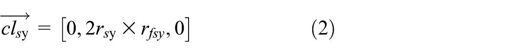

where


The y- and z-axis assembly error due to tolerance of the screw hole (dashed yellow lines are for reference, and dashed green circles are linkage screw holes).
Total assembly errors between connecting linkage module and supporting module
The total assembly error between the connecting linkage module and supporting module occurring in the joints is expressed as the sum of the upper and lower panel joint assembly errors. At this time, the assembly errors in the joints in the upper and lower panels are under the same conditions. Accordingly, if the machining error from one linkage joint is 1, the assembly error from the assembly of two linkages via two joints can have a maximum error of 2.
The x-axis assembly error between the connecting linkage module and supporting module results from the joint clearance. As shown in Figure 9, the assembly error in the joint occurs toward the x-axis, as described by the following examples. When the linkage is ideally positioned, the total assembly clearance is 0 (Figure 9(a)). When the linkage is positioned outward, the total assembly clearance is

where

The x-axis assembly error due to joint hole margin.
The y- and z-axis between the connecting linkage module and supporting module result from the joint hole margin. As shown in Figure 10, the assembly error in the joint hole exists along the y- and z-axis, as described by the following examples. When the joint hole is ideally positioned, the total assembly clearance is 0 (Figure 10(a)). When the joint hole of the connecting linkage module is positioned outward and the joint hole of the supporting module is positioned inward, the total assembly clearance is


where
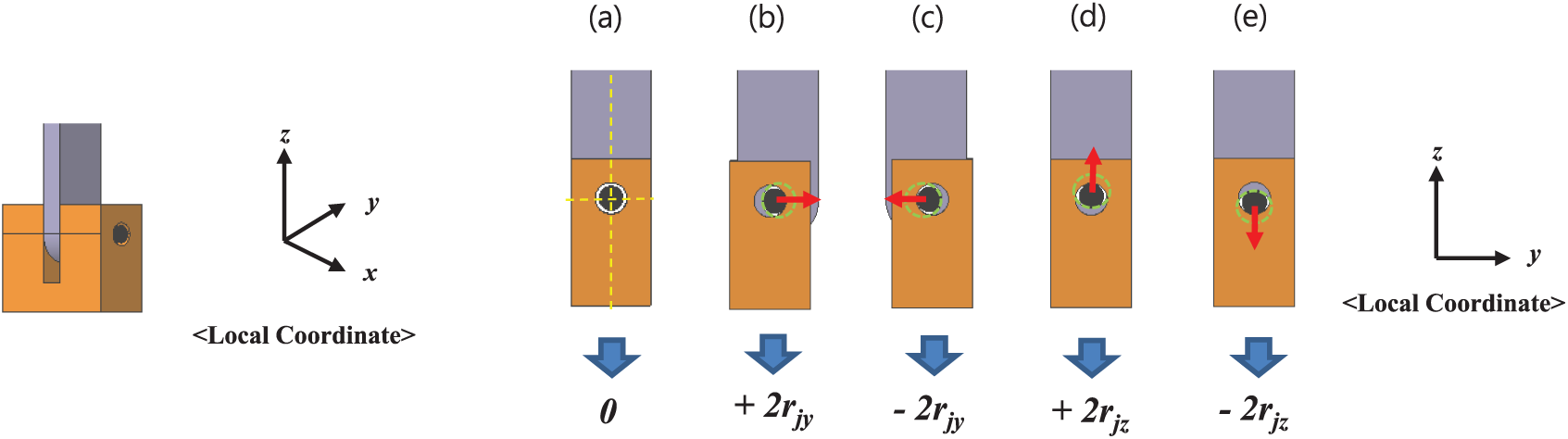
The y- and z-axis assembly error due to joint hole margin (dashed yellow lines are for reference, and dashed green circles are linkage joint holes).
The total accumulated assembly error between the connecting linkage module and supporting module

The above procedures can be summarized as follows. The total accumulated assembly error

where
To perform the calculation in the global coordinate system, the error vector of

where
The ideal position vectors for
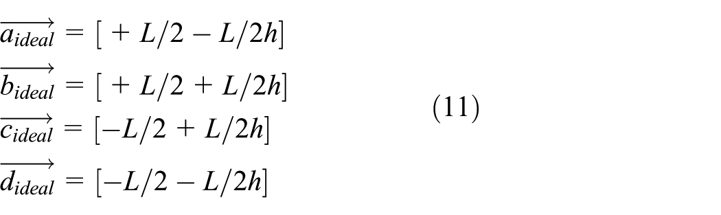
where L is the length of plate and h is the height of the structure.
The actual position vector from the origin of the global coordinate to each joint of the upper panel is obtained by adding the ideal position vector to the error vector, as shown in Figure 11


Real position vector of a joint with the ideal position vector.
Because the final assembled upper panel is a rigid body combined with linkages, cases that do not satisfy the rigid body condition are excluded in the calculation process for the degree of alignment. Then, the distance condition between two actual position vectors utilizing four position vectors (

where L is the length of the plate, r is the joint clearance,
With the above equations, the distance condition of a rigid body is applied. However, the distance condition is necessary in a rigid body condition. To satisfy the rigid body condition, additionally it is essential to consider the summation of the diagonal line’s heights. Therefore, the condition for each component of the height of the diagonal line,
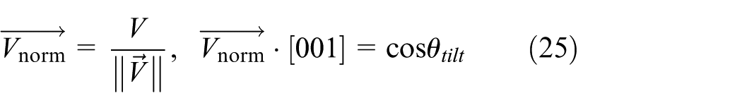
To calculate the tilt, the two vectors (

Position vector used in analysis.
Consequently, the tilt degree (equation (14)) is obtained by utilizing the vertical direction unit vector ([0, 0, 1]) and the normalized normal vector


A numerical simulation using MATLAB is performed with the dimensions, machining tolerance, and joint clearance of the model presented in Table 2. In order to obtain the simulation results for improved quarter, half, and full models in Table 3, as key design parameters, we considered the size of each model and forces of spring hinge and ball plunger for each model. In detail, the operating force for each model is selected by proportionally adjusting the stiffness of the spring hinge and the latching force of the ball plungers. In case of the machining and assembly errors, they are assumed to be identical regardless of scale of the model. The simulation results for the basic model reported in the previous article 18 and the improved models (quarter, half, and full model) with a customized apparatus (i.e. customized linkage, supporting module, and assembly jig) are shown in Table 3. Based on the simulation results for the basic and improved quarter model, it is possible to conclude that the cone-shaped linkage, ball plunger, and latching device contribute to reducing the tilt and de-center errors. In addition, the assembly jig plays a role in reducing the de-space errors as well as the tilt and de-center errors. Overall, each component and assembly jig fully satisfy the original design concept with respect to obtaining significantly improved alignment for the three evaluation items (i.e. tilt, de-center, and de-space).
Dimension, machining tolerance, and joint clearance for the improved quarter simulation model.

Simulation results of basic model and the improved model.
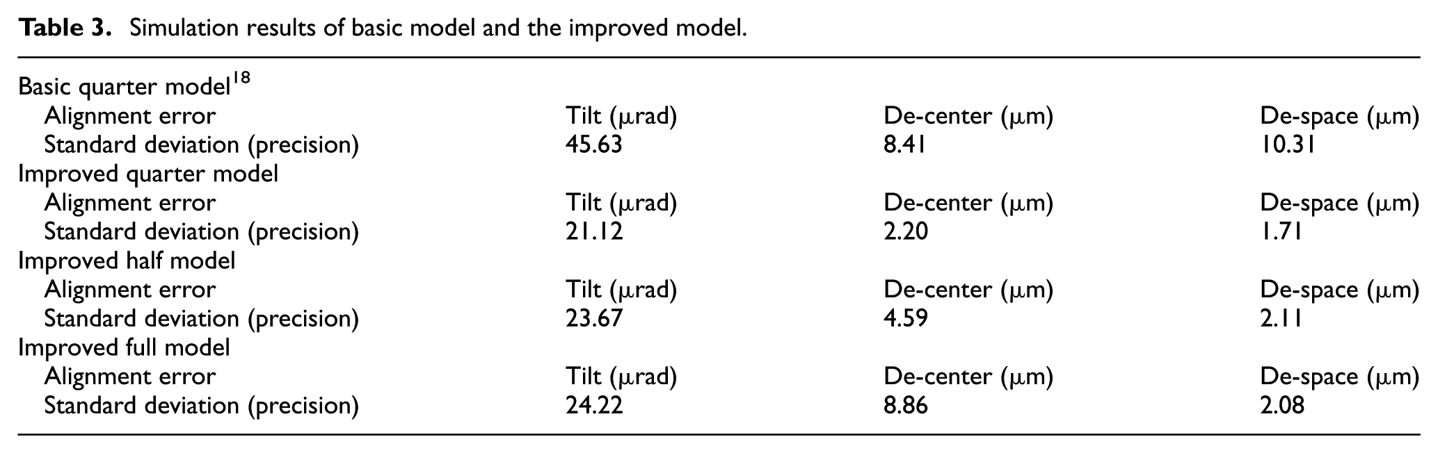
Based on the simulation results with the improved quarter, half, and full models of the deployment mechanism, we are able to determine the correlation between the alignment errors and dimensions. In the case of tilt and de-space, they do not depend on the dimensions of the deployment mechanism but instead depend on the machining tolerance and joint clearance (Table 3). On the contrary, de-center increases linearly depending on size. When we compare the alignment of the proposed mechanism (full model) with that of KOMPSAT-3, de-space and de-center are shown to be suitable for the requirements. However, tilt is 24.22 µrad, which is a little bit larger than required. It is in the range that can be corrected using the focusing mechanism. 15
Manufacturing and alignment measurement
Considering the costs of fabrication and space for the experimental setup, therefore, we employ the quarter model of the deployment mechanism to fabricate the deployment mechanism (Figure 13) since the full model results can be interpolated from the results of the quarter model.

Fabricated deployment mechanism: (a) the passive deployable mechanism in the deployed configuration and (b) one pair of linkage and supporting module.
Measurement platform
To serve as an optical device, a deployable optical structure requires high precision alignment between the primary and secondary mirrors. Therefore, a high precision measurement platform with sub-micron resolution is required to properly measure the alignment errors of a deployable optical structure. In this article, therefore, a high precision measurement platform is presented that utilizes five non-contact-based laser displacement sensors (KEYENCE, LK-G80, 0.2-µm resolution) to measure the alignment errors of a deployable optical structure. As shown in Figure 14(a), the proposed measurement platform employs two laser displacement sensors to investigate the transverse displacement of the upper panel, and three laser displacement sensors to scrutinize the longitudinal displacement of three particular points on the upper panel.

Measurement platform. (a) Basic platform: a. b. c. Vertical direction laser displacement sensors; d. e. Horizontal direction laser displacement sensors; and f. Upper panel. (b) Schematic representation of the improved measurement platform for gravity compensation.
De-center and de-space are calculated from the measured values of two horizontal direction laser displacement sensors and three vertical direction laser displacement sensors, respectively, for the upper panel. By combining the measured values from all laser displacement sensors, finally, tilt is calculated. 24
Measurement results
After 20 times deployment experiments in the measurement platform of Figure 14, the measurement results are obtained as in Table 4. The alignment results on the ground show different results from the simulation. This difference comes from an effect of gravity. In order to confirm the accuracy of the measurement results, it is necessary to derive the results correcting the gravity effect.
Measurement results of basic model and improved model without gravity compensation.

Gravity compensation
To serve when deployed in the vertical direction against gravity, de-space occurs due to the effects of gravity and causes a failure, that is, the designed deployment height is not reached. In addition, due to the effects of deflection, de-center occurs in the direction of gravity, while tilt occurs simultaneously. For these reasons, gravity compensation must be performed. Therefore, the measurement platform is improved, as shown in Figure 14(b). The basic measurement platform is installed in the cage of the improved platform, and alignment error of the mechanism for all gravity directions is measured by a two-axis rotation (X and Y).
The assumptions concerned with gravity compensation are as follows. Under the vertical configuration (Figure 15(a)), gravity only affects the results of the z-axis direction. When measuring the vertical direction, the components of each measured coordinate vector are written as follows

where
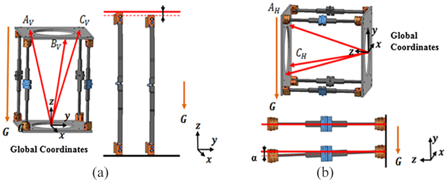
Gravity compensation according to the arrangement of the mechanism: (a) vertical configuration and (b) horizontal configuration.
Under the horizontal configuration (Figure 15(b)), gravity only affects the results of the y-axis direction. When measuring the horizontal direction, the components of each measured coordinate vector are written as follows

where
Under the horizontal configuration, the deflection angle at the upper panel is set as α = 0.006507 rad of the experimental results.
Assuming that the components of each compensated coordinate vector are written as


Based on aforementioned equations, the gravity compensation alignment error is calculated as follows


The measurement results with gravity compensation are shown in Table 5. Conclusively, the gravity-compensated experimental results are very close to the simulation results. However, there remain some differences between the experimental results and the simulation results because the clearance between components is assumed to be in a specific range that is permitted to have a ±5 µm tolerance for component machining.
Measurement results with gravity compensation.

Conclusion
This article proposed a new mechanism to guarantee a degree of alignment sufficiently high so as to be applicable to a deployable space telescope. For that purpose, cone-shaped linkages, a ball plunger, and a latching device were designed specifically to reduce the de-center, tilt, and de-space alignment errors. Before fabricating the components, the effects of each component with respect to their ability to reduce the alignment errors were investigated based on numerical simulations. In addition, in order to derive the results of the alignment errors that could occur in orbit, simulations under zero gravity conditions were carried out. The simulation was performed according to the size of the model, and the simulation results for the quarter model produced a tilt of 21.12 µrad, de-center of 2.20 µm, and de-space of 1.71 µm. Subsequently, the quarter model was constructed by assembling the fabricated components based on the design results. In particular, an assembly jig was designed, fabricated, and utilized to assemble the connecting linkage module. In addition, in order to understand the degree of improvement of the proposed deployment mechanism, the basic model and the improved model were manufactured, and the alignment errors were measured.
The alignment error measurement platform was designed and constructed to minimize the errors that might occur during the measurement process. The non-contact measurement platform was designed to measure the x-, y-, and z-axis using five laser displacement sensors. Using this platform, alignment errors were measured for each model equipped with cone-shaped linkages, ball plungers, latching devices, and so on. Then, based on the measurement results, the influence of each component on the degree of alignment was investigated. As a result, the x- and y-axis tilt and de-center were improved by preventing the distortion of the linkage by adding the male/female cone-shaped linkage joint. The y-axis tilt and de-center were improved by mounting a ball plunger. The role of the latching device was confirmed to improve the overall de-center by preventing distortion in the x- and y-axis while acting as a spring damper.
Finally, a gravity-compensated measurement platform was designed and fabricated to measure alignment errors that might occur on orbit. The gravity compensation platform was designed to allow free rotation in two axes and to change the direction of gravity acting on the rotation of the measurement model. The influence of gravity on the alignment error measurement was analyzed and compensated based on the tendency of the alignment error according to the rotation of the measurement model. Finally, the alignments (tilt, de-center, and de-space) of the deployment mechanism were experimentally investigated with the measurement platform consisting of five non-contact-based laser displacement sensors. The experiment produced a tilt of 30.04 µrad, de-center of 8.92 µm, and de-space of 4.03 µm. Although these results are a little bit larger than the required alignment for the conventional optical structure, it is worth noting that they are in the range that can be corrected using the focusing mechanism.
Footnotes
Handling Editor: James Baldwin
Declaration of conflicting interests
The author(s) declared no potential conflicts of interest with respect to the research, authorship, and/or publication of this article.
Funding
The author(s) disclosed receipt of the following financial support for the research, authorship, and/or publication of this article: This work was supported by Global Surveillance Research Center (GSRC) program funded by the Defense Acquisition Program Administration (DAPA) and Agency for Defense Development (ADD).