
Abstract
In order to increase the accuracy of a 6-axis motorized fiber alignment stage, a geometric and kinematic error model was established. A low-order body array was introduced to describe the general topological structure of the alignment stage; a homogeneous error transformation matrix was adopted to present the combination and kinematic errors of a typical case in a multi-body system; the structure and kinematic relationship of a 6-axis motorized fiber alignment stage as well as the corresponding error equation were built via the multi-body system error theory; the error distribution state and sensitivity characteristics of the 6-axis motorized fiber alignment stage were further analyzed; and the error compensation strategy was developed. The experimental results indicated that using inline error compensation for improving the alignment accuracy of the automatic alignment system for optical waveguide devices was very effective.
Introduction
Since the 1980s, optical fiber communication technology has generated revolutionary developments in the communication industry through the advantages it offers such as wide band systems, huge information capacities, low transmission losses, and anti-electromagnetic interference.1–3 Fiber communication devices such as planar waveguide splitters, 4 array waveguide gratings, 5 and optical switches 6 are the basis of fiber communication networks, along with the premise of realizing low-loss alignment couplings of the fibers and the optical waveguide chips.7–9 The core diameter of a single mode fiber is 8–9 μm, and the optical channel section feature size of an optical waveguide chip is 4–8 μm, both of which are micron-level dimensions. Studies have shown that if inspected with the extra loss of 0.15 dB, the optical tolerances of transverse dislocation, the longitudinal spacing, and the axial angle between the optical waveguide chip and the optical fibers were 1 μm, 16 μm, and 0.65°, respectively. 10 Therefore, the positioning accuracy of the alignment platform must be at the submicron level, to meet the precise alignment requirements necessary for the optical fibers and the optical waveguide chips.
During the process of alignment coupling for the fiber and optical waveguide chip, the 6-axis motorized stage was necessary in order to conduct precision adjustments of the optical fibers of the input/output array fibers, as shown in Figure 1. Owing to manufacturing characteristics of components, assemblies, and other parts, there exist inevitable errors in the motorized stage, and combinations of various types of errors that would cause the stage to deviate from its predetermined path, resulting in increased alignment difficulties.11,12 In order to increase the kinematic accuracy of the optical fiber and waveguide chip alignment, a geometric and kinematic error model of the 6-axis motorized stage was necessary. The error distribution state and sensitivity characteristics of the stage were analyzed by combining them with characteristics of the optical fiber alignment, and an error compensation method was then developed, to achieve low-loss alignment of the optical fibers and optical waveguide chip.

Schematic of the alignment of the optical waveguide chip and fibers.
Modeling of geometric and kinematic errors has been extensively applied in the fields of coordinate measuring machines and numerically controlled machines.13,14 Optical fiber alignment has its own unique characteristics, and in the process of alignment, the optical power, rather than the optical fiber position, is used as the feedback, which is an indirect feedback, while the three coordinate measuring machines as well as the numerically controlled machine both set the position as the feedback, which is a direct feedback. The 6-axis motorized stage has different forms for making combinations, and the propagation of geometric and kinematic errors is also different, and thus the alignment strategy, alignment accuracy, and alignment times for the optical fiber and the optical waveguide chips are all influenced by these differences.
A multi-body system error theory, based on typical body descriptions and homogeneous coordinate variation, has been introduced in this article, and an error analysis model of the 6-axis motorized optical fiber alignment stage was built by referring to the error analysis achievements of both the coordinate measuring machine and the numerically controlled machine, to analyze the error distribution state and sensitivity characteristics. The causes of geometric and kinematic errors in the optical fiber alignment stage are stated in section “Analysis of the causes of geometric and kinematic errors.” The topological structure and basic theory of optical fiber alignment stage errors are introduced in section “Topological structure and error description,” and general error model derivation is presented in section “Propagation of geometric and kinematic errors.” The error sensitivity factors are analyzed and discussed, and error compensation strategy is presented in section “Analysis and discussion.”
Analysis of the causes of geometric and kinematic errors
A 6-axis motorized stage has series, parallel, and composite types of structural styles. The series type is combined in the form of building blocks, which is convenient for control, and the perpendicularity among the axes is greatly affected by assembly errors. The parallel type is based on the Stewart platform, with the advantages of a high degree of accuracy and a small volume; however, the decoupling control is very complex. The composite type, with a structure containing a flexible hinge and a composite drive, combines the advantages of both the series and parallel types; having high accuracy, small volume, and control convenience, but with the drawback of a high cost.
Errors in the series type of 6-axis motorized optical fiber alignment stage are a combination of all the errors of the various motorized platforms (three translation and three angle), and the errors of the different motorized platforms are caused by multiple error factors. Therefore, the influence of various errors on the optical fiber alignment coupling depends on the fundamental errors of all the motorized platforms, as well as the position errors of the different motorized platforms. Errors of all the motorized platforms are dominated by geometric errors and thermal deformation errors, in which the geometric errors are the most fundamental, and are caused by the machining errors of the components and parts, as well as the assembly errors. The machining error of the components and parts is a reflection of the processing equipment errors during processing, restricted by processing equipment and processing accuracy. The manufacturing costs and degree of manufacturing accuracy increase in a geometric progression with the degree of manufacturing difficulty and may reach absurd heights. The assembly error is a human factor, which completely depends on the skill levels of the operation workers, from the components, to parts, to motor units, and then the multi-axis motorized stages. Assembly errors are inevitable, but they can be decreased.
Compared with coordinate measuring machines and numerically controlled machines, the travel length of the motorized optical fiber alignment stage is shorter, with a travel length of about 10 μm; the volume is also smaller and it can be put into an environment of constant temperature and humidity and thus the influence of temperature can be ignored.
Topological structure and error description
Topological structure of the system
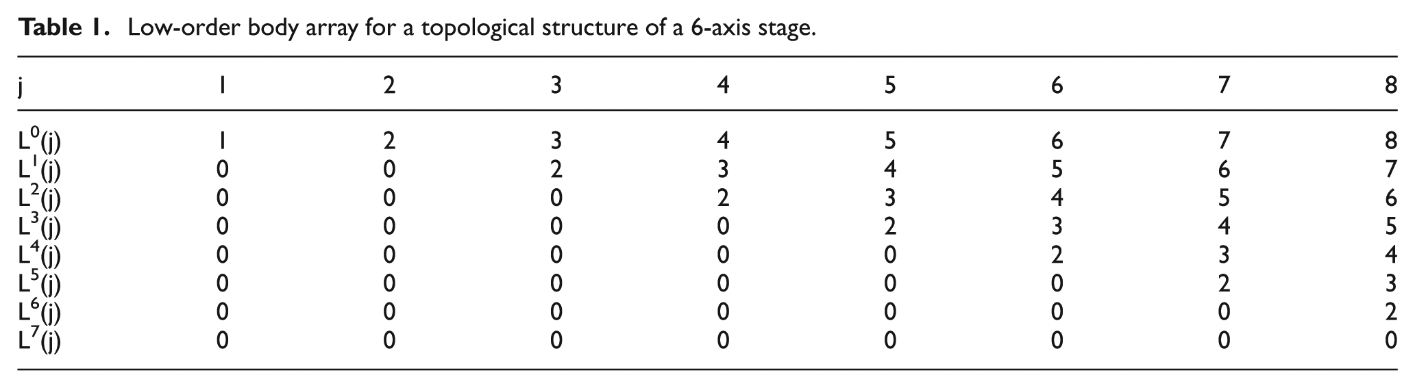
The series type of 6-axis motorized stage has different combinational forms. An X indicates the motorized platform in the direction of X, Y indicates the motorized platform in the direction of Y, and Z indicates the motorized platform in the direction of Z. An α is used to express the motorized platform rotating around the X-axis, β expresses the motorized platform rotating around the Y-axis, and γ expresses the motorized platform rotating around the Z-axis. For example, Z→X→γ→Y→β→α, Z→X→Y→γ→α→β and Z→X→Y→γ→β→α are commonly seen. The rotating platforms in the various combinations require the rotation center to be aligned, and the optical axis height should be as low as possible to stabilize the stage. The former two combinational forms have the structure of a cantilever beam, with poor stage stability. The third combinational form, that is Z→X→Y→γ→β→α, as shown in Figure 2, is based on multi-body system theory. The topological structure of the 6-axis stage is shown in Figure 3, the low-order body array of its topological structure is listed in Table 1, and the degree of freedom is presented in Table 2. A 0 indicates the mounting base, a 1 indicates the optical waveguide chip, and an 8 signifies the fiber array.

Schematic of an optical fiber alignment stage combination.

Topological structure of the 6-axis stage.
Low-order body array for a topological structure of a 6-axis stage.
Degree of freedom for a topological structure of a 6-axis stage.

Description of geometric and kinematic errors
There are 6 degrees of freedom between any two objects, so when any two adjacent objects are fixed and joined, or in a relatively static condition, the geometric error will occur at one of the 6 degrees of freedom directions, which is called static error or position error. When they are in a state of motion, the geometric error will also occur at one of the 6 degrees of freedom directions, which is called kinematic error.15,16 The static error depends on the degree of accuracy in the process of fixation and joining, or the positioning and orientation process in a relatively static condition, and is affected by factors such as temperature, vibration, and stress, while the kinematic error depends on the motion accuracy during the motion process and is related to the motion quantity.15,16
According to the multi-body system theory,17,18 the motion between the adjacent objects consists of 6 basic motions: three translation and three rotation motions. Therefore, when the kinematic error produced in each basic motion process is given, the kinematic error of the resultant motion will also be known. For example, at the X-axis, there are two basic motions, the translation and rotation (α axis) motions, and both of those motions will produce six kinematic errors related to the motion quantity. The geometrical significance is shown in Figure 4.

The six major types of errors in motion platforms: (a) six major types of errors in X translations and (b) six major types of errors in α rotation.
According to the coordinate translation and rotation change rule, the homogeneous characteristic matrix was adopted, to describe the comprehensive transformation matrix that was caused by the errors of
The optical fiber alignment stage was combined with highly accurate motorized platforms, which have small axis angular errors of

That is
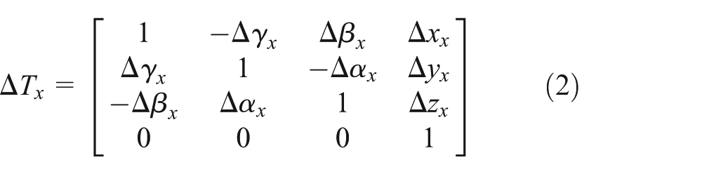
In the formula, the corner mark indicates various errors caused by motion along a specific axis.
The kinematic error characteristic matrix of rotation around the X-axis was

That is

The kinematic error is the function of kinematic parameters, and the error caused by linear motion is related to the translation distance, while the error produced in the rotational process is related to the intersection angle. The position error of all the motion platforms was the product, which was irrelevant to the kinematic parameters, including verticality or parallelism errors among the different motion axes and errors produced in the loading process of the optical fibers, the optical waveguide chip, and the fixture. For example, the static error characteristic matrix of verticality between the X- and Y-axes was
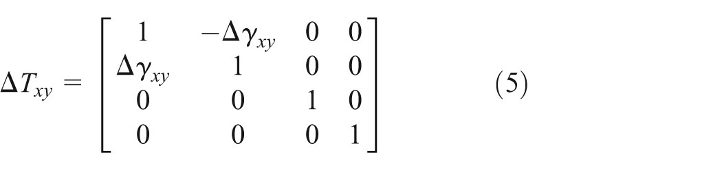
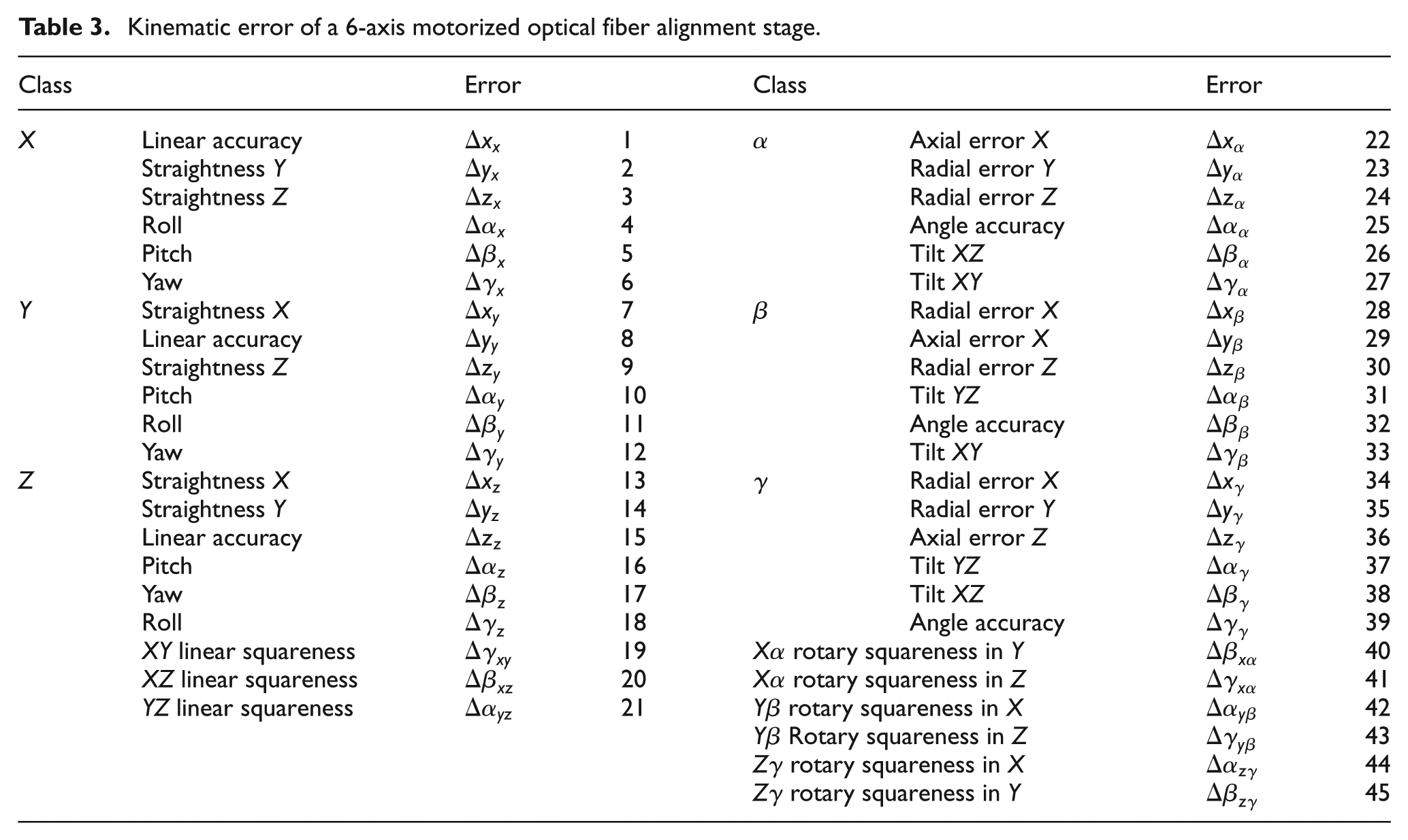
In a similar way, the kinematic error characteristic matrix of translation along the Y- and Z-axes, and along rotations around the Y- and Z-axes (β-axis and γ-axis), as well as the static error characteristic matrix among other axes, can also be obtained. Expressions and geometrical significance of the 6-axis fiber alignment coupling platform are given in Table 3.
Kinematic error of a 6-axis motorized optical fiber alignment stage.
Propagation of geometric and kinematic errors
A characteristic matrix of the 6-axis motorized stage is shown in Table 4, in which, if the characteristic matrix equals
Characteristic matrix of the 6-axis motorized stage.

Designating the array fiber as the chief channel, which means that the coordinate of CH1 in its fixture coordinate system would be

Analysis and discussion
Error sensitivity analysis
Alignment sensitive error is an error term which has a great influence on the optical waveguide chip and optical fiber alignment in a 6-axis motorized optical fiber alignment stage error source, including any factors that are amplified or reduced in the error propagation process. This concept provides the theoretical basis for studies on pose accuracy control in the processes of optical waveguide chip and optical fiber alignment. The sensitive error of the alignment platform is obtained first, and then the methods of error prevention as well as error compensation are adopted to control such errors. According to research,
10
the alignment error sensitivity is in the direction of X and Y, so the error sources producing
Based on Figure 2, point F (875, 100, 500 μm) is assumed in the array fiber coordinate system; in calculations, the linear motion error is designated as 0.30 μm, the angular motion error is 50 μrad (or about 0.003°), and the installation non-orthogonal error of various platforms is 50 μrad (or about 0.003°). The unit linear displacement is 1 μm, and the angular displacement is 1.7 mrad (or about 0.1°). The ultimate functional value and direction of various error sources can be obtained according to formula (6).
The ultimate function values and the directions of various linear error sources are presented in Table 5 (refer to the linear error explanation in Table 3 for the error source marks in the table). In situations where there is no non-orthogonal error among all the motion platforms, the linear errors of all the motion platforms are almost equally reflected in the same direction, especially the sensitivity direction of alignment, which must be strictly controlled. On the contrary, due to the non-orthogonal errors among the motion platforms, there exist errors in the directions of X, Y, and Z in the optical fiber coordinate system, and there is error amplification in the sensitivity direction of the alignment error, with error in the direction of X amplified by 0.06 μm, and error in the direction of Y amplified by 0.0563 μm. The error in the direction of Z is amplified by 0.1838 μm, but it cannot be regarded as the sensitive error direction. Therefore, non-orthogonal errors among motion platforms have a great influence on the linear error, so they must be strictly controlled, and the method of compensation may be adopted when the error is inevitable, to achieve high alignment accuracy.
Ultimate function values and directions of various linear error sources.

The ultimate function values and the directions of various angular error sources are shown in Table 6. In situations where there is no non-orthogonal error among all the motion platforms, the angular errors will cause a linear error in the vertical direction, with the maximum error at the sensitivity direction X of an alignment of 0.025 μm (caused by the angular error
Ultimate function value and direction of various angular error sources.

When comprehensive error distributions in both linear motions and angular motions are to be considered, the concept of an “accuracy field” is needed, and the space distribution of the alignment coupling point is described based on the space error model of the 6-axis motorized optical fiber alignment stage, by being combined with the motion process, as is shown in Figure 5. It can be seen that in linear motion, the influence of the comprehensive error on the error sensitivity directions of X and Y is the same. In angular motion, the influence of the comprehensive error, on the error sensitivity direction X, is larger, and the error sensitivity direction Y as the same.

Accuracy field distribution of 6-axis alignment stage: (a) error
Error compensation analysis
Optical fiber alignment and numerical control precision processes are similar to each other, but not precisely the same. Optical fiber alignment has optical power feedback, and all motion platforms move according to the preset pattern until the output’s optical power reaches its maximum, while numerical control processing moves according to a preset track, without online feedback regarding the feature accuracy of the processed parts. Optical fiber alignment emphasizes single step kinematic error and backward error, so error compensation will be considered according to optical fiber alignment characteristics, and it will be processed with pertinence and selectivity, unlike precision numerical control processing.
Based on the accuracy transfer model and the optical fiber alignment characteristics of the 6-axis motorized optical fiber alignment stage, consideration will only be given to excursions caused by non-orthogonal coupling errors among the various motion platforms, the backward error (backlash), and the misalignment of rotation centers. Non-orthogonal alignment error among various motion platforms is a static type of error, caused by the processing and assembly of components and parts and determined when the platform assembly is completed. It does not change with platform motion. Backward error is an inherent attribute of the platform motion transmission device and generally does not change with the platform motion. Both non-orthogonal coupling error and backward error can be accurately measured through laser interferometers and laser collimators and can be used as the standard for error compensation of the optical fiber alignment platform. Misalignment of rotation centers will cause derivative displacement and collisions when space between the optical waveguide chip and the array fiber is small; however, it can be corrected by translation.
The backward error precision angle platform of optical fiber alignment is small, at about 0.005° (or 87 μrad), and can be ignored. Only the backward error caused by the linear motion platform needs to be compensated for. Based on the alignment error compensation strategy in Figure 6, formula (6) can be simplified as

Error compensation method of optical fiber alignment.
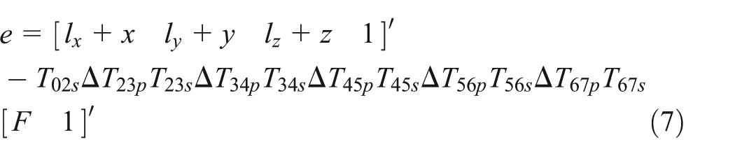
For the backward error, the compensation quantity is directly overlaid in the control instructions when there is a counter motion on the online platform, and the compensation quantity is set according to the actual measurement results. A non-orthogonal coupling error is related to the motion quantity, and the error compensation quantity is calculated according to formula (7):
Experiment
Automatic alignment system
Figure 7 shows the configuration of the automatic alignment system for optical fibers and optical waveguide chips. The input and output fiber arrays were set on 6-axis precision stages on either sides of the chip. The bidirectional repeatability of the X, Y, and Z motorized position stages was 0.3 μm, and the bidirectional repeatability of the α, β, and γ motorized position stages was 0.001°. The two 6-axis precision stages were driven by a computer using a General Purpose Interface Bus (GPIB). Two charge-coupled devices (CCDs) and lenses were adopted for the visual monitoring system, with the two CCDs placed vertically and orthogonally, to achieve the angular alignment and spacing control of the input/output fiber arrays and optical waveguide chips. A high stability laser source and a two-channel optical power meter were adopted and connected to the computer with the GPIB. The command system was operated by the computer, receiving real-time optical power signals and commutation, and feedback operations.

Structural figure of automatic alignment system.
Error compensation is set up in the alignment algorithm. According to Figure 6, the experiment is realized in two steps, the first group is without error compensation and the second group is with error compensation, thus obtaining the alignment results.
Alignment of optical fibers and optical waveguide chips
The optical waveguide chip used for automatic alignment coupling was a 1 × 8 planar optical waveguide splitter chip, and the optical channel section feature size of the optical waveguide chip was 8 × 8 μm2. The end face of the optical waveguide chip and optical fiber array were both planar-milled. The adhesion used for bonding the coupling interface was a refractive index matching adhesion. As shown in Figure 6, the experiments were set up with two groups. The first group, which was uncompensated, had a backward error of straight stages of 0.3 μm. The second group was compensated by formula (7).
Tables 7 and 8 show the experimental results of the two groups’ automatic alignment coupling. The theoretical insertion loss of various channels of the 1 × 8 planar optical waveguide splitters was 9.03 dB, which means that the only influence was the splitting ratio. The others were alignment coupling loss, transmission loss of the chip, and others. Transmission loss of chips was related to manufacturing technology and processing; it was an inherent loss, and it was generally less than 0.1 dB/cm. 4 Alignment coupling loss was a loss caused in the process of device packaging and manufacturing, and it was related to motion platform, alignment coupling technology, algorithms, and so on.
Alignment results of a fiber array, a 1 × 8 splitter, and a fiber array system with no error compensation (insertion loss, dB).

Alignment results of a fiber array, a 1 × 8 splitter, and a fiber array system with error compensation (insertion loss, dB).

As shown in Table 7, for a 1 × 8 planar optical waveguide splitter, many repeated experiments basically guaranteed that the insertion loss of the device channels was less than 11.14 dB, with a maximum uniformity of 0.22 dB, and an average alignment time of 3 min. According to Table 8, it was clear that for a 1 × 8 planar optical waveguide splitter, many repeated experiments basically guaranteed that the insertion loss of the device channels was less than 9.92 dB, with a maximum uniformity of 0.20 dB, and an average alignment time of 2 min. From Tables 7 and 8, over 1 dB coupling loss reduction was observed, but the uniformity of coupling loss was no changed. Because the automatic alignment algorithm was the same before and after error compensation, and the uniformity of coupling loss was influenced by the manufacturing accuracy of optical waveguide chip, fiber array, and alignment algorithm. From Tables 7 and 8, it could be assumed that using this inline error compensation for improving the alignment accuracy of the automatic alignment system for optical waveguide devices was very effective.
Conclusion
The analytical methodology for geometric and kinematic error compensation of a 6-axis motorized optical fiber alignment stage has been provided based on multi-body system error theory. Low-order body array was adopted to describe the general topological structure of the alignment coupling platform for this method. A homogeneous error transformation matrix was used to present the error and the error distribution states. Sensitivity characteristics of the platform were further analyzed and discussed, and the error compensation strategy was developed. The experimental results indicated that using inline error compensation for improving the alignment accuracy of an automatic alignment system for optical waveguide devices was very effective. This study will serve as a reference for designs that increase the accuracy of 6-axis motorized optical fiber alignment stage systems.
Footnotes
Academic Editor: Chuanzeng Zhang
Declaration of conflicting interests
The authors declare no competing financial interest.
Funding
This work was supported by the National Natural Science Foundation of China (grant nos 51475479 and 51075402), the National High-Tech R&D Program of China (grant no. 2012AA040406), the Research Fund for the Doctoral Program of Higher Education of China (grant no. 20110162130004), and the Natural Science Foundation of Hunan Province, China (grant no. 14JJ2010).