
Abstract
In minimally invasive surgery, flexible needle insertion is a popular application which has been extensively researched. However, needle steering is challenging for a bevel tip cannula flexible needle due to the nonholonomic constraints and the rebounds of the needle shaft when the needle tip is reoriented. We proposed a novel kinematic model for the bevel tip cannula flexible needle based on bicycle and unicycle models, taking consideration of the deflection of the bevel tip and the rebounds of the needle shaft. Aiming at different types of paths, forward kinematics of the model was analyzed and calculated. Each parameter of the kinematic models was identified based on the experimental data using the least square method. Furthermore, the changing rules of parameters were explored under different angles of the bevel tip. The experimental results show that the errors of the proposed kinematic models are within 2 mm, which is greatly reduced compared to the traditional bicycle or unicycle model, and fulfill a general clinical surgery.
Keywords
Introduction
Minimally invasive surgery (MIS) is a brand new medical treatment, which has been developed rapidly in recent years. It wins good graces for its advantages of fewer traumas, rapider effectiveness and fewer complications, and so on. And it will be an inevitable developing trend of surgical treatments in modern clinical medicine. Needle insertion is a commonly used treatment in MIS, such as tissue biopsy and brachytherapy applied in prostate, liver, or brain. Nowadays, rigid steel needles are commonly used in the surgeries. However, due to the structural complexity of human body and uncertainty of practical operations, the traditional rigid needle can hardly meet the needs of complex surgeries, that is, it is not only difficult to rectify the deviated path (even though they often can be visualized), but also unable to steer clear of the obstacles (like bones) or sensitive tissues (like nerves and blood vessels). Targeting errors or failure arrivals to the target can diminish the effectiveness of therapies or bias the diagnosis results depending on the accuracy of needle placement. Thus, the needle steering technique is the key for the needle insertion procedures, while the kinematic model is the basic research for the steering, that is, we have to perform path planning and even control of the needle based on the kinematic model. 1
Webster et al. 1 proposed a bevel tip flexible needle (BTFN), which is usually made of nitinol (an alloy of nickel and titanium). The needle is supposed to be flexible enough to bend inside the tissue because of the lateral resistance acted on the bevel tip when inserted. Thereafter, other kinds of flexible needles with different types of bevel tips are generated.2–4 Ko et al. 5 proposed a programmable bevel tip probe: the offset between two interlocked segments of the probe determines the bending direction and radius. Among all kinds of flexible needles, the BTFN proposed by Webster et al. has been widely accepted and extensively studied. However, the BTFN mainly has two drawbacks: one is that the curvature of the needle path is almost invariable in a certain tissue and the path can hardly be rectified if it is deviated; and the other is that the reorientation precision of the bevel tip is low inside the tissue, because there is a torsional friction along the needle shaft.
We have proposed a cannula flexible needle, which comprises a flexible cannula and a flexible stylet, as shown in Figure 1. The cannula and the stylet have relative translations and rotations. And both drawbacks above mentioned can be easily overcome by the cannula flexible needle: first, it generates a set of variable-curvature paths by inserting the stylet with different lengths of d out of the cannula; second, because the stylet and the tissue are separated by the cannula, the torsional friction along the stylet is greatly reduced; hence, the reorientation precision of the bevel tip is fundamentally improved.
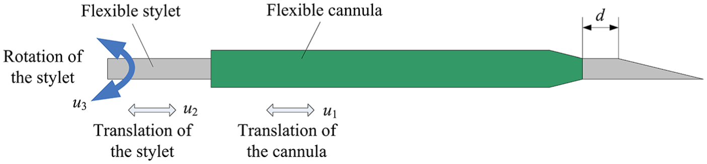
Cannula flexible needle.
Kinematic modeling for the BTFN steering is challenging due to the nonholonomic constraints of the needle and has been widely studied by scholars. DiMaio et al. formulated a needle Jacobian that described needle tip motion due to the needle base movement and proposed a model for the tissue based on a finite element method (FEM). However, the study was concerning a symmetric-tip needle. 6 Alterovitz et al. simulated bending of the BTFN based on FEM. The simulation modeled the effects of the needle tip and frictional forces on soft tissues defined by a two-dimensional mesh. 7 Chentanez et al. 8 proposed an interactive needle insertion simulator based on FEM that modeled the coupling between the BTFN and deformable tissue. However, the FEM is time-consuming and cannot generate any general analytic equations. Misra et al. 9 first developed a mechanics-based model for the BTFN steering, which can be used to predict the needle behavior based on mechanical and geometrical properties of the needle. Wang et al. 10 also developed a mechanics-based model to predict the needle deflection, utilizing the beam theory and the Rayleigh–Ritz method. Datla et al. 11 presented an energy-based model to predict needle deflection of an active bevel-tipped needle when inserted into tissue. Khadem et al. 12 proposed mechanics-based model for simulating a planar needle insertion in soft tissue based on the beam theory. Jiang and Wang 13 also proposed a mechanics-based model for the BTFN insertion based on the quasi-static principle and the dynamics of the needle motion. However, the mechanics-based or the energy-based models are complex and also time-consuming, which may not be suitable for a real-time prediction or path planning.
Webster et al. 1 proposed a bicycle model (BM) and a unicycle model (UM) for the BTFN, considering the path of the needle was equivalent to a path of a bicycle or a unicycle. Other kinematic studies on the BTFN were similar to the BM or the UM.14–16 These kinematic models are the analytic equations, which are appropriate for calculation of paths. Therefore, a great deal of path planning has been studied based on the BM or the UM.17–19 However, these models neglect the elasticity of the needle shaft, assuming that the needle is completely flexible and the needle tip “stays in place” during reorientation. As a matter of fact, the needle tip will rebound to some extent during reorientation, which definitely causes a large error between the model and the actual path. Moreover, different types of conjunctions between segments of a path, for example, arc-arc (A-A), line-arc (L-A), or arc-line (A-L), will have different rebounds. Although literatures1,10,20 proposed models to predict double bendings (i.e. A-A), they did not take account of the rebound in their models. In our previous work, we proposed a deflection unicycle model with rebound (UMR), which was a modified UM, and calculated the kinematics of a path with A-A type for the BTFN. 21 However, to our best knowledge, there is no existing study on kinematic models sorted by different types of paths, and no previous work on model parameter identifications considering the rebounds of L-A or A-L for the BTFN. Especially, there is no previous work discussing the changing rules of each parameter. In this article, we will propose a novel kinematic model for the cannula flexible needle. We are going to establish the models for the different types of paths (including the single arc, A-A, L-A, and A-L) considering the deflection of the needle tip and the rebounds of the needle shaft, calculate the kinematics, identify the model parameters, and even explore the changing rules of parameters for the kinematic models of the cannula flexible needle.
Kinematic model and calculation of cannula flexible needle
Establishment of kinematic model
Motion analysis
Different with the traditional BTFN, which has 2 degrees of freedom (DOF)s, that is, insertion and rotation, there are 3 DOFs for the cannula flexible needle: translation u1 for the cannula, translation u2 and rotation u3 for the stylet. The radius of the needle path is varied by the length d inserted out of the cannula. The larger the length d gets, the smaller the radius will be. Therefore, the relative movement of u1 and u2 changes the curvatures of paths, while u3 determines the directions of bending. However, after adjusting the length d, we usually input u1 and u2 simultaneously in the same velocity in order to get a certain radius of path; thus, we denote u1 and u2 as u12. If u12 and u3 are input separately, an arc-based path will be generated, see Figure 2(a). If u12 and u3 are input simultaneously, and the speed of u3 is much smaller than u12, a helix-based path will be generated, see Figure 2(b); however, if the speed of u3 is much larger than u12, a linear path will be generated, see Figure 2(c). 22

Motion forms: (a) arc-based path, (b) helix-based path, and (c) linear path.
Modified unicycle model
First, let us recall the BM and the UM as a reference (see Figure 3). The functions of the needle path for the BM and the UM are as follows


Bicycle and unicycle models: (a) bicycle model and (b) unicycle model.
The experiments showed that the BM was more accurate than the UM for a single arc. 1 In order to simplify the kinematic calculation and not to diminish the accuracy of the kinematic model, we propose a new modified unicycle model (MUM), which is similar to BM for a single-arc path. However, in contrast with the BM, the number of parameters in the MUM is reduced into two

Because of the gap between the needle and its support, when the cannula flexible needle is bending, the bevel (i.e. the wheel) will be deflected at the end of the support. Thus, the arc path of the needle is not the original unicycle path; instead, it is virtually an arc with a deflection of the wheel (rotation about x-axis by φ), as shown in Figure 4. Therefore, we should modify it with a deflection φ. The MUM is only suitable for the path start with an arc (A-A and A-L), but not suitable for that start with a line (L-A).
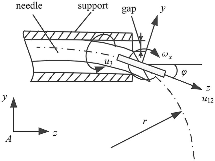
Modified unicycle model. The bevel is deflected by an angle φ with respect to the needle axis.
Models with rebounds
Although the MUM (or the BM) is more accurate than the UM, it remains intolerant errors for non-single-arc paths. The main cause is under the assumption of “staying in place” of the needle tip during reorientation. As a matter of fact, when the needle is rotated inside the tissue, the bevel direction changes, and the effective interaction area between the bevel and the tissue will be reduced; thus, the resistance acted on the tip is also reduced. This will lead to a certain rebound of the needle tip, as shown in Figure 5. Hence, a large error occurs between the actual path and the prediction of the MUM, as shown in Figure 6. Thus, we have to take account of the rebound after reorientation. Moreover, different types of paths will have the different rebounds. So we propose a UMR and a modified unicycle model with rebound (MUMR). The superiority of the modification of the rebound is obvious, and the experimental contrasts are available in Zhang and Zhao. 21
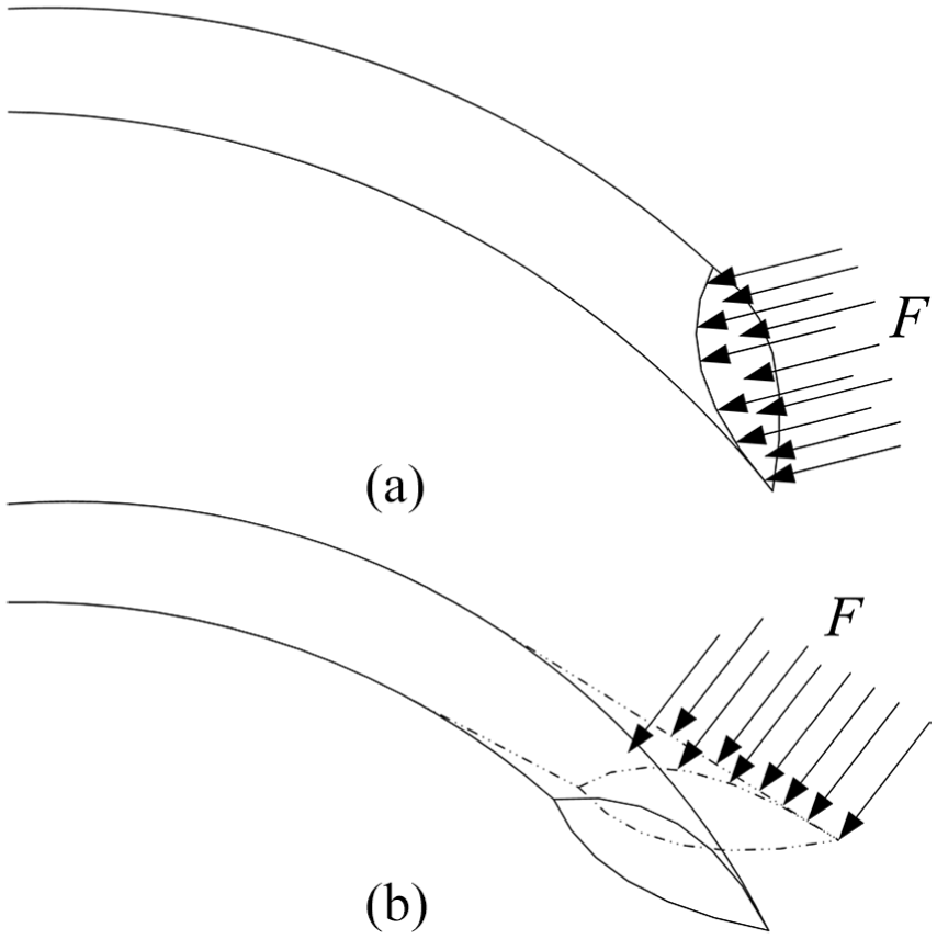
Rebound of the needle: (a) before rotation and (b) after rotation.
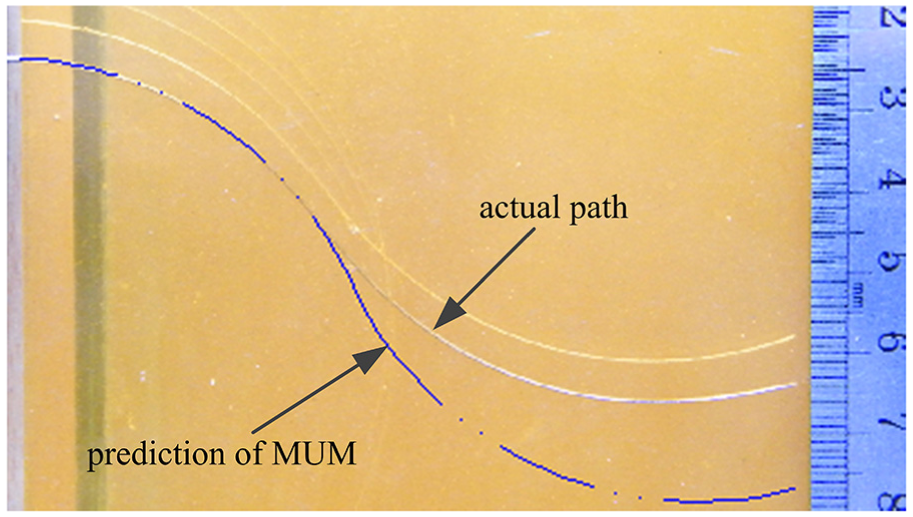
Comparison of actual path and prediction of MUM.
Of course, different rotation angles of the needle shaft will result in the different rebounds, which is more complicated; however, in this article, we focus on the study of the path in a plane (rotation with 180°).
Now, we sort the paths into three types, that is, A-A, L-A, and A-L, as shown in Figure 7. The needle tip is inserted to the point N. After rotation, the segment CN of the original path will rebound to be the segment CD, as shown in Figure 7(a) and (b). While for L-A, the needle is inserted to the point N, after insertion of the arc, the segment CN will be pulled into CD because of the lack supporting of the tissue. So we define CDs as rebounds (noted as

Rebounds of different types of paths: (a) A-A typed path with rebound, (b) A-L typed path with rebound, and (c) L-A typed path with rebound.
Kinematic models for different types of paths
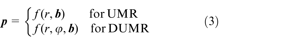
To sum up, the kinematic models of the cannula flexible needle are the modified UMs, which are improved with the deflection and the rebounds, that is, if the first segment of the path is an arc (including a single arc), the path needs to be modified with the deflection to the UM (i.e. MUM); however, it need not for the path that the first segment is a line (i.e. UM). If the path consists of multiple segments, it needs to be modified with the rebounds (i.e. UMR or MUMR). And the general function of the kinematic model is formulated as follows

where r is the radius of a segment; φ is the deflection angle of the wheel, if the first segment of path is a line, φ = 0, and the model is degraded into the UMR;

Kinematic calculation
Calculation for unicycle kinematic model
As shown in Figure 3(b), the configuration of the needle tip frame B relative to the world frame A can be described by a homogeneous transformation matrix
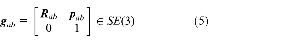
where
In frame B, the twist

where
Then, the homogeneous transformation matrix can be rewritten into an exponential form

where
Kinematic calculation for single segment
For a single segment, all we have to consider is to modify with the deflection and do not need to consider the rebounds. According to equation (7), the homogeneous transformation for the MUM can be obtained as follows

where

However, when t = 0,
While if the single (or the first) segment is a line, it need not be modified with the deflection; thus,

where
Kinematic calculation for multiple segments
Kinematic model for multiple segments is rather complicated. Not only the deflection but also the rebounds have to be taken into account. Since the whole path can be discretized into several segments, let
If the rebounds are neglected, the forward kinematics after insertion of n segments is formulated as

where T is the total insertion time of the whole path,
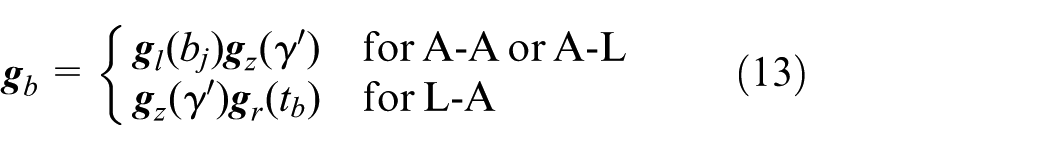
As a matter of fact, there are rebounds existing in the path; therefore, we have to modify each segment until the last one, that is, to add transformations of the rebounds between segments. As shown in Figure 7, let BN be the ith segment with the transformation matrix

where tb is the modified time, that is, the insertion time for the length of the rebound, and different rebounds possess the different modified times,
The transformation for the rebounds is as follows
where
Thus, the kinematics of the MUMR is as follows

Parameter identification for kinematic models
Parameter identification in single arc
From equation (4), we can conclude that the center of the arc is a function with the parameters of r and φ

where r is the radius of the arc; φ is the deflection angle.
In order to identify the two parameters, we use the MUM to fit the single arc. Let the starting point be p0 (0, y0, z0), and a sample point in the path be pi (0, yi, zi), as shown in Figure 8. We assume that the needle axis is initially aligned with the z-axis of frame A and the center of the arc O (xc, yc, zc) is formulated as follows


Position relations in single arc.
Since the position of pi is in the arc centered at O; thus, we have
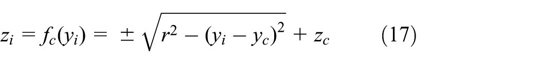
where “±” depends on which side of pi located at O; if zi > zc, it is “+”; on the contrary, it is “–.”
The least square method is adopted, and the both parameters of r and φ can be identified by

where
Although the calculation in equation (17) includes “±” signs, the sign is certain with the relative position of pi to O; therefore, the calculation is definite. Thus, the identification of the parameters is unique, and the same as the following parameter identifications.
Parameter identification in A-A
We use the MUMR to fit the path A-A in order to identify the parameters of r, φ, and b1. The center O1 of the first arc is identical with that of the single arc, that is

Let the length of the first segment BN be S1, and the second segment be S2, which are assumed to be known in advance according to the insertion length (see Figure 7(a)), so we have
where S1 is the length of the first segment; b1 is the rebound of A-A; r is the radius of the arcs.
In the triangle O1CE, we have

So

where φ is the deflection angle.
The distance between the two arc centers

Thus, the coordinates of O2 can be expressed by the position of O1
For a point pi(0, yi, zi) in the path, the relationship between yi and zi is as follows

where j represents the jth segment, j = 1, 2; “±” depends on which side of pi located at Oj, for the first segment,
Then, the least square method is adopted again. By substituting equation (25) into equation (18), the three parameters of r, φ, and b1 can be identified.
In the identification, although the path consists of two segments, the coordinate data are definite for the equations of each segment. Thus, the identification of the parameters is unique also, and the same as the following parameter identifications.
Parameter identification in A-L
We also use the MUMR to fit the path A-L in order to identify the parameters of r, φ, and b2. The center O of the first arc is also identical with that of the single arc, as formulated in equation (19).
For a point pi(0, yi, zi) in the first segment, the relationship between yi and zi is the same as equation (17). Also let the length of the first segment BN be S1 (see Figure 7(b)), so we have

where S1 is the length of the first segment; b2 is the rebound of A-L; r is the radius of the arc

where φ is the deflection angle.
Thus, the position of the point C is formulated as follows

The slope of the line is

And, for a point pi(0, yi, zi) in the linear segment, the relationship between yi and zi is as follows

Then, by substituting equations (17) and (30) into equation (18) for each segment, the three parameters of r, φ, and b2 can be identified.
Parameter identification in L-A
We use the UMR to fit the path L-A in order to identify the parameters of r, φ, and b3, as shown in Figure 7(c). Assuming that the needle is inserted in horizon, the first linear segment is formulated as

And the center O of the arc (the second segment) is formulated as follows

where S1 is the length of the first segment; b3 is the rebound of L-A; r is the radius of the arc.
And the relationship between yi and zi is the same as equation (17). Then, by substituting equations (17) and (31) into equation (18) for each segment, the three parameters of r, φ, and b3 can be identified.
Experimentation and result
Parameter identification
The needle experimental system consists of an insertion mechanism, a control system, and a block of phantom tissue, as shown in Figure 9. The insertion mechanism is composed of two screw–nut mechanisms, which are overlapped. The bottom one is to realize the insertion of both the cannula and the stylet by motor I. The upper one is to realize the insertion of the stylet relative to the cannula (adjusting the length d of the stylet out of the cannula) by motor II. And motor III which is mounted on the upper screw-nut drives the needle shaft spin.
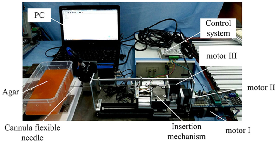
Experiment setup of the cannula flexible needle.
The cannula flexible needle used in the experiment was as follows: the stylet was a cylinder nitinol wire with the diameter of 1 mm, and with the bevel tip of 30°; and the cannula was a tube with the inner diameter of 1.1 mm and the outer diameter of 1.3 mm. In the experiment, the length d was set to zero, that is, only the bevel tip remains out of the cannula. And the phantom tissue was adopted as agar.
Although the parameter values (including r, φ, and
The velocities in the experiment were defined as v = 0.009 m/s and ω = 3.5 rad/s, respectively. The insertion lengths for each type of paths were as follows: 110 mm for the single arc, 50 mm for the first segment, and 60 mm for the second, respectively. Rotation angle for reorientation of A-A was 180° for sake of the planar paths. Each type of path was inserted for five times. One of the insertions for each type is shown in Figure 10, which was acquired by a digital camera. And the trajectories were obtained by using an image processing.

Experiments for parameter identifications: (a) single arc, (b) A-A, (c) A-L, and (d) L-A.
Assuming that all the radii of arcs in all types of paths remain the same, and in order to obtain unanimous parameters, we put all the experimental data together and fit all the parameters at the same time for the parameter identifications. The results are shown in Figure 11 and Table 1.

Fitting results: (a) single arc, (b) A-A, (c) A-L, and (d) L-A.
Parameter identification results.

RMS: root mean square.
From the results, we can conclude that the kinematic models fit the actual paths very well, with a little maximum error (less than 2 mm) and a little root mean square (RMS) of errors. This proves the validity of the proposed kinematic models with the presented parameters.
Kinematic model comparison
In order to compare the proposed models with the traditional bicycle or unicycle models, and prove the validity of the proposed parameters (the deflection and the rebounds), we also did experiments for the comparison. MUMR is with both the deflection and the rebounds, UMR is with the rebound but without the deflection, MUM is with the deflection but without the rebounds, and UM is without any of the parameters.
We chose the single-arc path and the A-A typed path, because they possess both parameters in the proposed models for the comparison. The results are shown in Figure 12 and Table 2.

Comparison of the models: (a) MUMR, (b) UMR, (c) MUM, and (d) UM.
Results of the models.

RMS: root mean square; MUMR: modified unicycle model with rebound; UMR: unicycle model with rebound; MUM: modified unicycle model; UM: unicycle model.
From the results, we can conclude that the models with rebound are much superior to those without it, and the models with deflection are superior to those without it. This proves the rationality of the proposed parameters.
Changing rules of parameters
As above noted, the parameters’ values of the models will vary under different bevel angles of the needle tip. In order to discuss the changing rule of each parameter under different bevel angles, we perform experiments with eight different angles of the needle tip, that is, 10°, 20°, 30°, 40°, 50°, 60°, 70°, and 80°.
Rule of radius r
The change of the radius r is continuous, and it seems to be symmetrical and with a minimum value, which accords with the change of cosecant function very much, as shown in Figure 13. Thus, the regression result of r is as follows


Cosecant regression for r.
The maximum error and the RMS of errors are 1.6538 and 1.0610 mm, respectively. This proves the rationality of the regression rule for r.
Rule of deflection φ
We respectively adopt a quadratic curve and a sine curve to regress the experimental data under different bevel angles, and the results are as follows

As shown in Figure 14 and Table 3, both regressions fit the data well, but they have the superiority of their own, the error of the quadratic result is a little less than that of the sine result; however, the sine result accords with the actual limitations for 0° and 90°, that is, theoretically, there will be no deflection (the value should be zero) if the bevel angle is 0° or 90°.

Regression results of φ under different θ.
Regression errors of φ.

RMS: root mean square.
Rule of rebounds b
We adopt quadratic curves to regress the experimental data under different bevel angels, and the regression results of
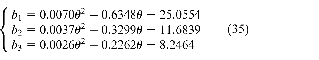
As shown in Figure 15 and Table 4, the results show that the regressions fit the data well. This proves the rationality of the regression rules for

Regression results of
Regression errors of

RMS: root mean square.
Conclusion and future work
Based on the BM and the UM, we proposed the modified kinematic models for the cannula flexible needle, taking consideration of the deflection of the bevel and the rebounds of the needle shaft when reorientated. Then, the kinematic models are sorted according to the different types of paths. Forward kinematics of each model is analyzed and calculated. The identifications for each parameter (arc radius r, deflection angle φ, and rebounds
Moreover, the proposed models are suitable for any planar path no matter how many segments it possesses. Because the path types mentioned in the manuscript are the basic elements, and a path is the conjunction of the basic ones. In addition, the model parameters remain the same, and the kinematics can be calculated, accordingly.
Although the real biological tissues are inhomogeneous and exhibit non-linear properties which are quite different from the agar phantoms adopted in our experiments, the kinematic models are similar, merely with the different values of parameters. Although this may cause the larger errors of the kinematic models, we could estimate and modify the parameters in a real-time control with a medical imaging technology and use a dynamic path planning algorithm to rectify the deviated path and diminish the errors.
In future work, we will study the sensitivity of the model with respect to these parameters, explore the relationships between the model parameters and the properties of needle or tissue, and further explore the rebounds with any other angles (not limited to 180°). Moreover, the study of path planning based on the proposed kinematic models for the needle steering is also valuable work.
Footnotes
Handling Editor: Inés Tejado
Declaration of conflicting interests
The author(s) declared no potential conflicts of interest with respect to the research, authorship, and/or publication of this article.
Funding
The author(s) disclosed receipt of the following financial support for the research, authorship, and/or publication of this article: This research is partly supported by the National Natural Science Foundation of China (grant nos 51305107 and 51675142) and by the Natural Science Foundation of Heilongjiang Province of China (grant no. ZD2018013).