
Abstract
This article designs an automatic flight control system for an unmanned aerial vehicle helicopter. The differential evolution intelligent algorithm is used for a state-space model identification; the differential evolution method has an advantage of choosing initial point randomly. The accuracy of the identified model is verified by comparing the model-predicted responses with the responses collected during flight experiments. The reliability and efficiency of the differential evolution algorithm are demonstrated by the experimental results. A robust controller is designed based on the identified model for the unmanned aerial vehicle helicopter with two-loop control frame: the outer-loop is used to obtain the expected attitude angles through reference path and speed with guidance-based path-following control, and the inner-loop is used to control the attitude angles of helicopter tracking the expected ones with
Keywords
Introduction
In recent years, unmanned vehicles have attracted a great deal of interest from the university, the industry, and the military world. The past decade has seen a golden age in the development of unmanned aerial vehicle (UAV), but there are only a few documented examples of small-scale unmanned helicopter applications in real-world scenarios; this is mainly due to the poor flight performance that can be achieved and guaranteed under automatic control.
The accurate model and proper control method are the important steps in flight control system design. The UAV helicopter model is a complicated system, and the system identification method is well suited to the rotorcraft problem. The UAV helicopter model is established by first principles. The nonlinear flight dynamic model of the unmanned helicopter is determined by choosing the body velocities, angular rates, and Euler angles as the state vector and the four helicopter control variables as the control input vector. A linear state-space model is derived from a nonlinear model for certain trim points using small disturbance principles. Conventional time-domain techniques are often not well suited to these difficult aspects of helicopter as discussed by Tischler and Ivler 1 and Hensen and Steinbuch, 2 while the frequency-domain methods are well suited to the rotorcraft problem.
Artificial intelligence (AI) is well suited to solving complex problems such as model identification, which is a logical reasoning process with many constrains. At the same time, AI can significantly enhance the intelligence level and autonomous capabilities of UAV, thus improving the level of cluster control. In this article, a nonlinear search based on differential evolution (DE) intelligent algorithm is conducted for a 6-degree-of-freedom (DoF) linear state-space model that matches the frequency-response dataset; the DE method has an advantage of choosing initial point randomly, and the reliability and efficiency of the DE algorithm are demonstrated by the experimental results.
A large set of control methods for UAV helicopter have been reported from classical control to neural-based adaptive control, and several typical methods are introduced as follows. Proportional–integral–derivative (PID) control 3 is the most popular method, but the high coupling of the UAV system cannot be solved. The optimal control method 4 which needs accurate model of UAV is not well suited. The neural-based adaptive control model 5 costs a long time to train, and the control frame is too complicated. H∞ loop-shaping method can systematically handle the multivariable and uncertain nature of the aircraft, 6 which can solve the channel coupling by loop-shaping method, the accurate model is not needed due to the robustness of the control method, and do not need a long time to design the control system compared to the neural-based control method. The greatest common right divisor (GCRD) method is used to move the transfer function matrix from the real system to the target system, which is a very useful way to solve the difficulties in choosing a proper weighting matrix in loop shaping.
Frequency identification modeling method
Integrated window method
An integrated window method is used to combine the conditioned frequency response, achieving an integrated conditioned frequency response that has good coherence and low random error over the entire frequency range of interest, and the weighting cost function, J, to minimize at each discrete frequency is shown as follows

where
A function that varies inversely with the random error,

so that the data with the minimum error
The frequency-response function

The integrated result shown in Figure 1 indicates excellent identification (

Coherence of lateral channel.
Frequency response and ranges selected for identification.
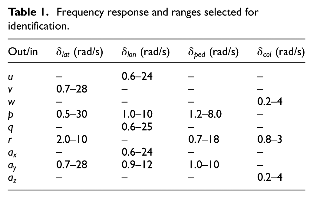
Simplified model based on frequency-response table
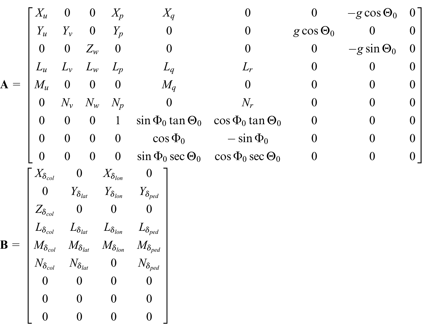
The state-space model of UAV helicopter is established, and the stability and control derivatives are identified by matching the conditioned frequency responses

where

where u, v, and w are the speed weight of the UAV; p, q, and r are the angular rate weight of the UAV;

The derivatives in the state-space model (3) are very small to be neglectable when the helicopter is in hover condition; if they are not dropped from the model, the identified results will be redundant. We will show how to reduce the model structure based on frequency-response table.
If the off-axis response is poor which means that the energy from input to output is weak, as r is the heading angle rate,

From equation (3), we can get equation (5) as follows

Combining equations (4) and (5), if equation (4) is satisfied, we obtain
According to the same analysis, when the helicopter is in hover condition, the frequency-response pairs
Model identification using intelligent algorithm
The following transfer function is obtained by taking the Laplace transfer of equation (3) 7

A weighted function J is determined by taking the error between the identification frequency response and the model response, and the unknown parameters in state-space model are obtained through minimizing J over a selected frequency range

where

where Wr is the weighting coefficient of the frequency response according to the coherence value; Wg is the weighting coefficient of the magnitude of the frequency response; and Wp is the weighting coefficient of the phase (degree) of the frequency response, where Wp = pi/180 = 0.01745, changing the degree to radian.
Each input–output pair in good coherence is selected for the identification, and an acceptable level of accuracy requires the cost function
Mutation
Mutation is to generate totally different individual randomly by different individuals as given in equation (8), and the mutation process is described in Figure 2


Mutation process of DE.
Recombination
Recombination operation is to copy individual as given in equation (9), and the recombination process is shown in Figure 3

where CR is a constant in the interval
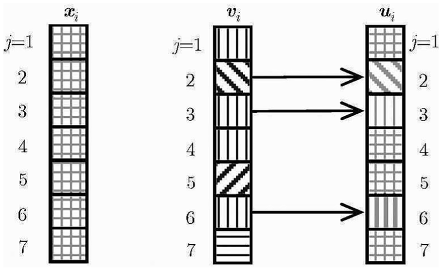
Recombination process of DE.
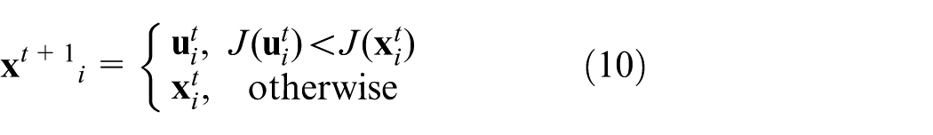
Selection
Selection operator is to choose better individuals using equation (10), which makes to converge to the best individuals
Design of the frequency sweep test
Raptor-50 UAV helicopter with a complete auto-pilot system is used to do frequency-sweep test as shown in Figure 4. Low frequencies are important for the identification of the speed derivatives, and high frequency excitations are important for the identification of the coupled dynamics. To guarantee that the flight data capture the dynamics, a frequency-sweep technique is used, where the pilot gradually increases the frequency of the input from 0.1 to 5 Hz. Figure 5 shows the flight data of input and output by frequency-sweep test. The input is the control input, outputs are the helicopter states, and the sampling rate of the test is 100 Hz.
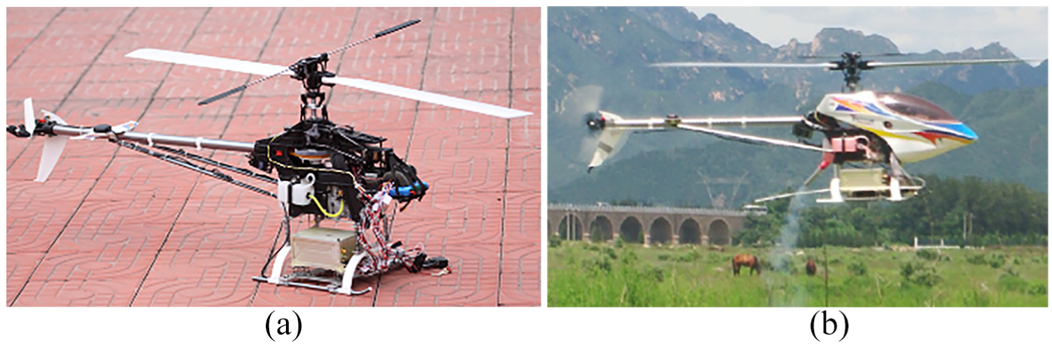
Instrumented UAV helicopter in experiment: (a) ground test and (b) frequency-sweep test.

Input and output by frequency-sweep test.
Identification results and model verification
The frequency responses computed from the flight data (solid) and the identified model are compared in Figure 6, which indicates that identified model and flight data are in good agreement. The model identified should be verified to ensure it can predict the real dynamic response accurately. Figure 7 shows the verification results in the time domain, which indicates that the model identified is well matched.

Frequency response from the flight data and identified model.

Identified model verification results.
Robust controller design
loop-shaping design process
The
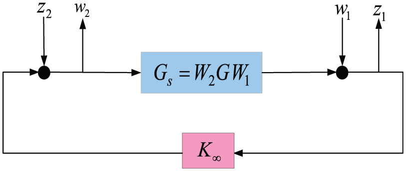

where

where
Coprime factor uncertainty is obtained by introducing perturbations to a left coprime factorization of G

Stabilizing controllers,

where

New method for weight matrix selection
Design engineers usually obtain good loop-shaping weights and controllers by choosing proper diagonal weights
This article uses GCRD method to transfer the transfer function matrix from the real system G to the target system
Definition 1
Let
Theorem 1
Let
where
Theorem 2
Let

where
In the following, we define

where
Then, we can get the minimal realization of


where
Next, we will use the GCRD method to transfer the transfer function matrix from the real system G to the target system
Let
Simulation of control performance
Simulation of inner-loop control performance
The traditional
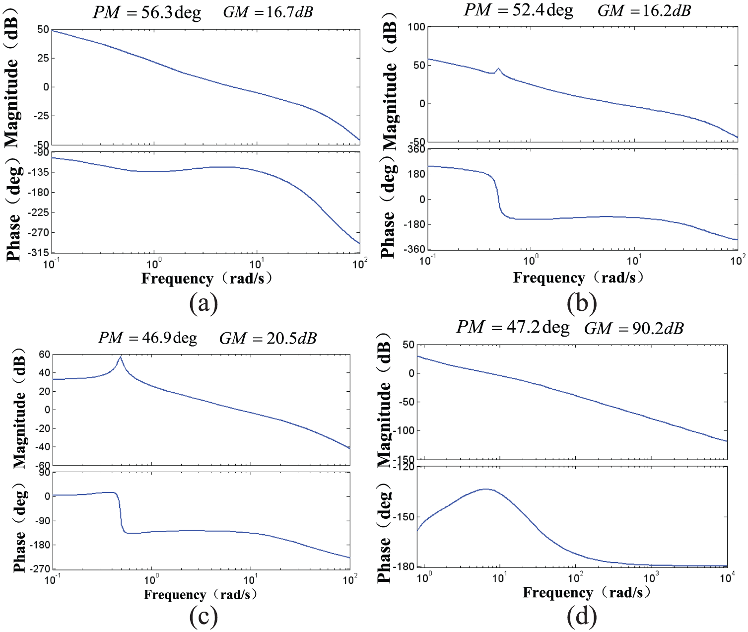
Bode plots for UAV single loop (traditional method): (a) w channel, (b) r channel, (c) φ channel and (d) θ channel.
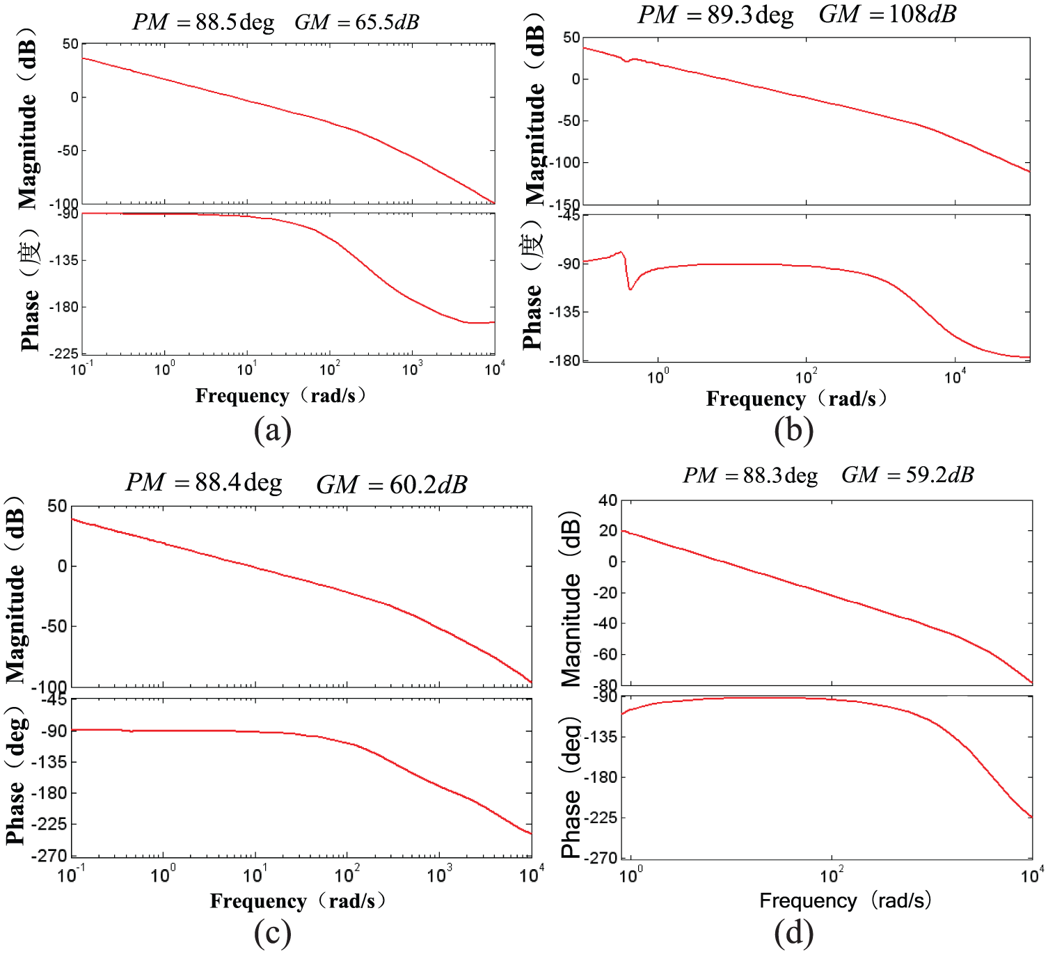
Bode plots for UAV single loop (GCRD method): (a) w channel, (b) r channel, (c) φ channel and (d) θ channel.
When the loop-shaping design was finished, equation (13) was maximized to achieve the 24-order controller
The simulation results proved that the stability performance of the unmanned helicopter system achieves a top-level performance in accordance with the ADS-33E-PRF.
11
Table 2 compares bandwidth
Bandwidth evaluations with ADS-33E.


Normalized responses to pulse disturbance: (a) traditional method and (b) GCRD method.
Simulation of outer-loop control performance
The inner-loop closure makes available a high-bandwidth, robust, and decoupled system with four inputs (

Simulation results of the climbing helix trajectory tracking.
Conclusion
This article designed an automatic control system for a UAV helicopter based on intelligent algorithms; the frequency identification method is used to extract the UAV helicopter model, and DE intelligent algorithm is used to get the unknown matrix derivatives of the UAV model, using the
Footnotes
Handling Editor: Yaolong Liu
Declaration of conflicting interests
The author(s) declared no potential conflicts of interest with respect to the research, authorship, and/or publication of this article.
Funding
The author(s) received no financial support for the research, authorship, and/or publication of this article.