
Abstract
The laser shock peening effect and its influence on rolling contact fatigue of ferrite–pearlite steel were investigated experimentally. Microhardness on the steel surface is increased after laser shock treatment. The depth of surface layer affected by laser shock hardening is above 1 mm. The maximum residual compressive stress generated on the specimen surface is around 1 GPa. The twin-disk test showed that laser shock-treated steel disk presents better rolling contact fatigue resistance than untreated one. Laser shock-induced strain hardening and compressive residual stress alter crack inclination angle and propagation behavior, which results in a longer fatigue life.
Introduction
Recently, there have been a lot of studies on fatigue mechanism and modeling of fracture behavior of engineering materials and structures in pressure vessel, compressor disk, and turbine blade using multiscale and probabilistic approaches.1–9 Ferrite–pearlite steels are widely used in railway components such as wheels. Wear and rolling contact fatigue (RCF) are two of the most crucial subjects.10,11 Due to the improvement of wear resistance of ferrite–pearlite steel by optimizing chemical composition and adopting strengthening methods, 12 the failure caused by wear is rare to happen, while RCF becomes more common and represents one of the main failure causes. In the past few years, extensive research works have been conducted to investigate the mechanism and influence factors of RCF of wheel and rail steels both experimentally and numerically.13–22
Recently, a series of laser surface treatment technologies, such as laser melting, laser cladding, and laser dispersed treatment, have been applied for improving wear and RCF resistance of wheel and rail steels.23–25 Those laser treatment techniques change the microstructure and stress status within laser-treated zone and inhibit the treated steel from delamination wear and delay the initiation of RCF crack. Laser shock peening (LSP) is another laser surface treatment technique without involving much of microstructure evolution. It has been widely used to improve fatigue strength of metal components in aviation and automobile industries.26,27 In the LSP process, as shown in Figure 1, a pulsed high-intensity laser beam interacts with the absorption layer on the metallic target surface and generates the plasma. The plasma continuously absorbs energy from the laser beam but its expansion is constrained by the confining layer, resulting in a shock wave propagating into the target. Plastic deformation occurs if the amplitude of the shock wave exceeds the Hugoniot elastic limit (HEL) of the target material, and residual compressive stresses are induced near the material surface. The strain hardening and residual stress would enhance the fatigue life of treated target material. However, LSP of wheel and rail steels and its effect on RCF behavior were rarely reported.

Schematic of LSP process.
In this study, a ferrite–pearlite steel was processed by LSP with various laser power densities. The effect of LSP on microhardness and residual stress of steel specimen was investigated. The twin-disk rolling contact test was conducted to study the effect of LSP treatment on RCF behavior.
Experimental procedures
Materials
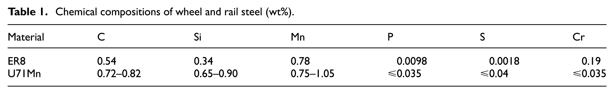
The ER8 ferrite–pearlite steel and U71Mn steel were used in this study, which are typical wheel and rail materials in China high-speed railway, respectively. Wheel and rail steel specimens were cut close to the wheel tread and the top surface of railhead, respectively, to ensure the uniformity of properties. Table 1 depicts the chemical composition of the materials.
Chemical compositions of wheel and rail steel (wt%).
LSP processing
The LSP treatment was performed by using a Q-Switched Nd:YAG pulse laser (Spectra Physics—Quanta Ray) with a wavelength of 1064 nm. The pulse duration (full width at half maximum, FWHM) is approximately 10 ns, and the energy of single laser pulse is about 2.4 J. The original laser beam size is about 12 mm in diameter. A focusing lens was used to adjust the beam size. The diameter of the focused laser beam on the specimen varies from 2.6 to 3.6 mm, resulting in the laser power intensity achieved at the sample surface varying from 2.2 to 4.4 GW/cm2 in this study. Multiple laser shots can be applied on the specimen, and the overlap ratio is controlled by an automated x–y table.
The wheel specimens for LSP study were cut into square shape with 10 mm in both length and width and 4 mm in thickness. Before LSP, the specimen surface was first ground using a sequence of increasing grit sandpaper, and a final polishing was done with 0.05 µm diamond paste. Al foil (40 μm thick) was attached to the surface of wheel specimen as the absorption layer, while the water or BK7 glass (4 mm thick) was alternatively used as a confining layer to achieve various laser-induced shock pressures.
The disk specimen with 45.4 mm in diameter, 10 mm in thickness, and 5 mm contact strip was cut and machined from the wheel steel. Before LSP processing, the disk was ground to surface roughness Ra = 0.8 µm. Because BK7 glass is not applicable for the curved shape of disk, water was used as a confining layer in LSP treatment of disk specimen. Two laser power densities of 2.2 and 4.4 GW/cm2 were chosen. The whole cylindrical surface of the contact trip was treated with the overlap ratio of 50%.
Property characterizations
A microhardness tester VTD512 with a diamond Vickers indenter in a face angle of 136º was used to measure the Vickers hardness of the peened wheel specimen. A vertical load of 200 g was applied for the measurement with a dwell time of 10 s at room temperature. There are two types of hardness tests conducted in this work. One is on the peened surface to see if there is any surface enhancement. The other is on the cross section of peened specimen to evaluate the affected depth of laser-induced shock. The sites for hardness tests on the peened surface were randomly chosen and those for hardness tests on cross section of peened specimen are in a zig-zag fashion. The typical distance between the two neighboring sites is above 400 µm to avoid possible interference of measurements. As for surface microhardness, an average of six measurements was used for each data point.
The phases and residual stress in the peened specimen were characterized with a Rigaku D/MAX2500 XRD system using the Cu-Kα1 X-ray source. Residual stress was calculated by the standard sin2Ψ method

where the material constants E = 210 GPa and ν = 0.28 are used for ER8 steel. The diffraction from the (200) crystallographic planes of the ferrite phase with the peak position 2θ = 65.04o was chosen for residual stress measurements.
RCF experiment
The RCF experiment of wheel/rail pair was carried out in an Amsler-type twin-disk test machine. Disk specimens were fabricated from ER8 wheel steel and U71Mn rail steel, respectively. LSP treatments were applied on the wheel disk surface, while the counter part of rail disk was untreated. As shown in Figure 2, the disks were mounted on two counter-rotating geared axles. The rail disk was located at the bottom as driving roller, while wheel disk at the top as the driven roller. The driver was controlled by a servo motor. The slip ratio between the two rollers was controlled by an eddy current brake employed on the driven disk side. The normal load of 1400 N was applied by screwing a spring system to simulate the realistic contact pressure in the wheel/rail pair. An accelerated test method of RCF with a small slip rate was used in this study. 28 The disk specimen was first run at a speed of 400 rpm for 15 min under dry condition while keeping the friction coefficient at approximately 0.25. The test was then continued by applying lubricating oil and hence a lower friction coefficient of 0.04. For the purpose of accelerating crack propagations and avoiding temperature flashing, UB3 hydraulic oil was introduced as a lubricant during the RCF test. The kinematic coefficient of viscosity and flash point of this oil were 32 mm/s2 and 473 K, respectively.

The twin-disk test for rolling contact fatigue experiment: (a) U71Mn rail disk as a driving roller and ER8 wheel disk as a driven roller and (b) the geometry of disk specimen (unit: mm).
Microstructure examinations
The specimens for microstructure examinations were first ground and polished and then etched by the alcoholic solution containing 3% of nitric acid (volume fraction). Micrographic observations were carried out with an optical microscope. The scanning white light interferometer was used to observe the profiles of worn wheel disk surfaces and measure the depth of pits. In order to understand the crack morphology and propagation behaviors, cross-sectioned specimens from wheel disk were prepared for microscopic observation.
Results and discussion
Peening effects
Vickers indentation test results in Figure 3 show peening effects on ER8 wheel steel induced by laser shock. The surface hardness of untreated ER8 wheel steel is about 210 HV. As shown in Figure 3(a), after LSP processing, the surface hardness increases to 230–240 HV for Al–water combination and 250–260 HV for Al–BK7 glass combination. The increase in surface hardness shows a slight dependence on the laser power density in the range of this study for each combination of absorption and confining media. In Figure 3(b), the measured hardness on the cross section of peened specimen increases in the surface layer and then decreases to the value of untreated specimen at a depth of about 1.2–1.4 mm for Al–water combination and 1.6–1.7 mm for Al–BK7 glass combination. This indicates that the thickness of the LSP affected layer can reach millimeter scale for the laser processing parameters in this study. Laser-induced shock pressure reaches its peak within tens of nanoseconds in a typical LSP process such that the material near the surface undergoes ultrahigh strain rate (105−107 s−1) plastic deformation. The peak pressure induced by laser pulse can be estimated by Fabbro’s model29,30

where α is the fraction of the internal energy devoted to the thermal energy (typically, α≈0.25), I0 is the laser power density, Z = 2 Z1Z2/(Z1 + Z2) is the reduced shock impedance between the absorption material (Al, shock impedance: 1.47×10⁶ g cm−2 s−1) and the confining medium (water, shock impedance 1.45×10⁵ g cm−2 s−1; BK7 glass, shock impedance 1.44×10⁶ g cm−2 s−1). The peak pressure generated by the pulsed laser in this study varies from 1.5 to 7.7 GPa. The peak pressures for Al–water (4.4 GW/cm2) and Al–BK7 (2.2 GW/cm2) are both approximately 5 GPa, which results in similar surface hardness increase and affected layer thickness.

The peening effect of wheel steel after LSP treatment with different absorption and confining layer combinations: (a) the surface hardness and (b) the hardness–depth profile.
It should be mentioned that twin-disk BK7 glass is not applicable for LSP treatment due to its curved shape. Therefore, LSP test with absorption medium of Al foil and confining medium of water was mainly discussed in the following section.
Figure 4 shows XRD spectra within 2θ scanning range 35o<2θ<95o for ER8 wheel steel subjected to LSP with various laser power densities. The reflections corresponding to crystallographic planes (110), (200), and (211) of α-Fe phase were indexed in this range. As shown in Figure 4, the α-Fe peaks shift to smaller diffraction angles after LSP, which indicates that there is residual compressive stress induced by the LSP process. There is no sign of γ-Fe peaks in the 2θ scan range. This observation indicates that there is no phase transformation after LSP in this study, while it is typical in laser-dispersed treatment of wheel steel. 24
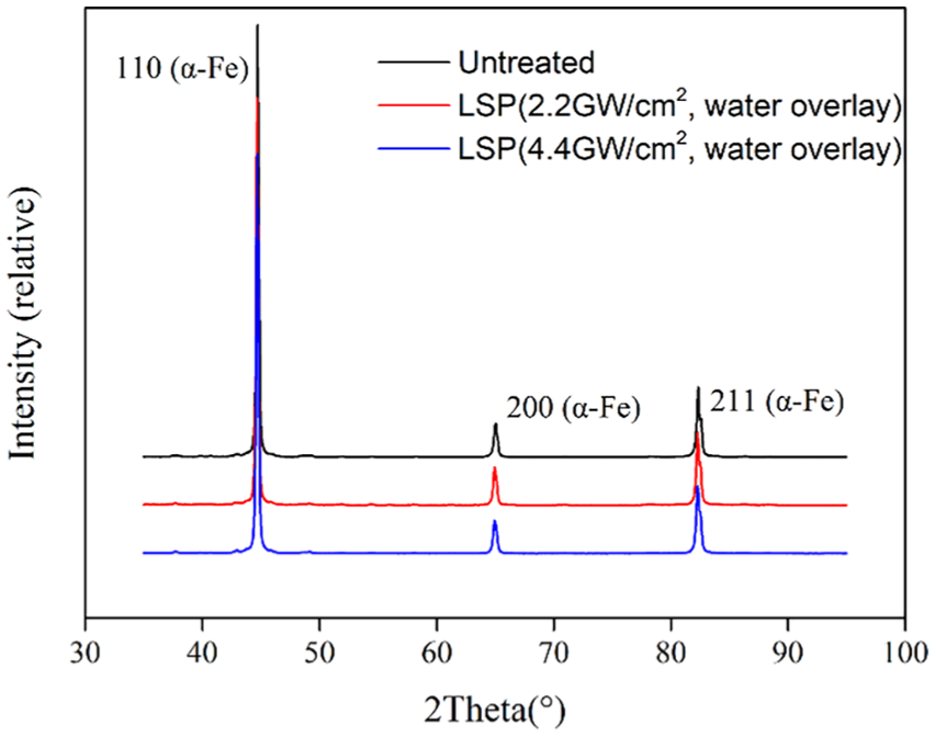
XRD spectra of ER8 wheel steel subjected to LSP.
The residual stresses of peened specimen were measured to be 946.5 and 1063.4 MPa in compressive state for laser power density of 2.2 and 4.4 GW/cm2, respectively. These results indicate that remarkable residual compressive stress can be introduced in the peened specimen by laser-induced shock. The existence of residual stress in the surface has significant effect on the measured indentation hardness,31–33 since a biaxial compressive stress leads to a smaller plastic zone and more pileup underneath the indenter, resulting in increased hardness.
RCF test results
The rolling cycle results of RCF tests of disk specimen are displayed in Table 2. According to the YB/T5345-2014, the materials are considered to be failure once the area of deep flaking exceeds 3 mm2 or more. Figure 5 shows the macromorphology of three wheel disks during the fatigue test. The untreated steel disk presented multiple pits after 6.1 × 10⁴ cycles and the areas of those pits were more than 3 mm2, while the LSP-treated steel disk only shows scattered small pits when experiencing the same cycles. It can be concluded that both LSP-treated specimens presented better RCF resistance under the speed and pressure in this study. Compared with specimen treated by LSP1 (Figure 5(b)) where several small pits appeared, the RCF damages were less obvious on specimen surface treated by LSP2 (Figure 5(c)). It can be concluded that LSP was able to enhance RCF resistance of ER8 steel, and this effect was even more obvious with larger laser power density.
Results of rolling contact fatigue tests.

The failure is defined according to the YB/T5345-2014.
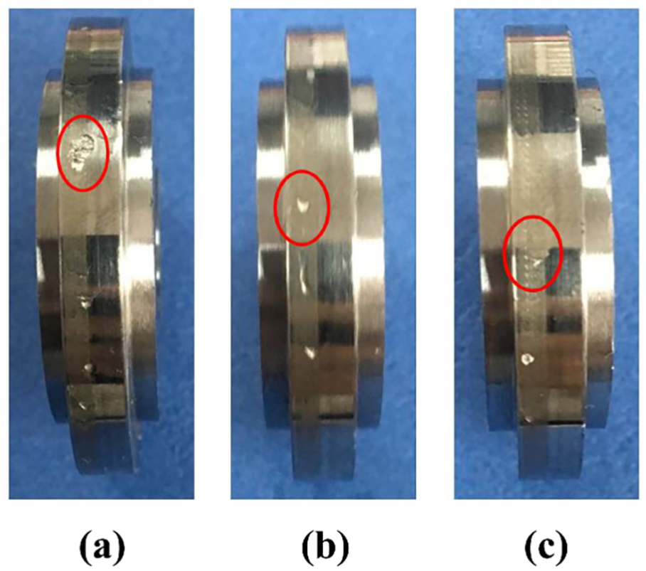
Macromorphology of wheel steel disks after fatigue test (N = 61,190 cycles): (a) untreated, (b) LSP1, and (c) LSP2.
Under rolling contact loading condition, most of the cracks initiate at the surface or the subsurface of the wheel, where the maximum shear stress occurs. 10 Because of the introduction of an accelerated test method of RCF in this study, surface-initiated crack formed during the first rolling stage under dry condition. Therefore, RCF behavior and fatigue life of wheel disk were mainly determined by the surface-initiated crack and its propagation.
RCF tests produce severe deformed microstructure within a small volume of material near the rolling contact surface (Figure 6). During the first phase of RCF test under dry condition, the material is deformed and orientates toward the friction direction, and the most severe deformation occurs at the contact surface, where surface-initiated cracks are formed. From the orientation of deformed microstructure shown in Figure 6, we can see that the untreated wheel disk shows the severer deformation than LSP-treated wheel disk. The severe deformation near the contact surface causes strain hardening behavior. Figure 7 shows the microhardness variation of wheel disks after the RCF test as a function of depth from the contact surface. The microhardness profiles from Figure 3 for two LSP-treated wheel steel before the RCF test are also plotted as comparison. It can be seen that the maximum strain hardening occurs at the contact surface, and then it gradually decreases and reaches the bulk hardness of the wheel steel until a certain depth. It should be noted that for LSP-treated wheel disk, the strain hardening due to rolling contact is superimposed on the laser shock-induced hardening effect. The increment between the original hardness and the worn surface is defined as rolling contact strain hardness. The rolling contact strain hardening zone is approximately 800 µm below the surface. From Figure 7, it can be seen that after rolling contact test the surface hardness of untreated wheel steel is larger than LSP-treated wheel steel, which indicates that the magnitude of rolling contact strain hardening of untreated wheel steel is larger than LSP-treated steels.
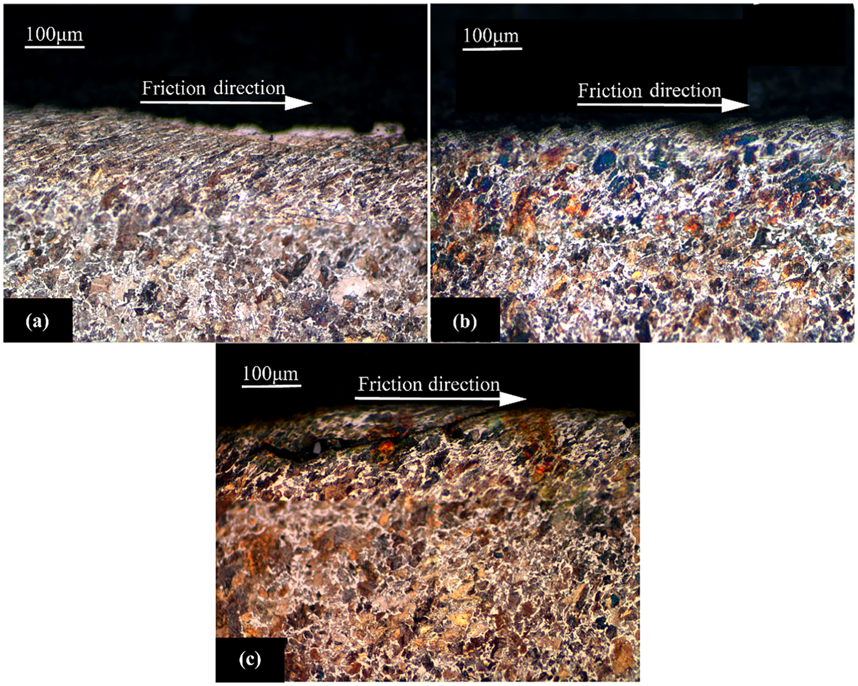
Cross-sectional microstructures of wheel disks show severe deformation and crack formation at the rolling contact surface: (a) untreated, (b) LSP1, and (c) LSP2.

Microhardness variation of wheel disks as a function of depth from the rolling contact surface.
According to the ratcheting deformation mechanism, cracks will eventually form if hardening behavior and residual stresses in the material are not sufficient to prevent further accumulation of plastic strains.34,35 As shown in Figure 6, the near-surface region of test disk is composed of highly strained ferrite and pearlite. Ferrite has different accumulation behaviors of plastic deformation from pearlite. The accumulation of plastic deformation in the ferrite begins earlier and increases at a higher rate than in the pearlite.36,37 Severe plastic deformation induces ductility exhaustion in the ferrite earlier than pearlite such that the ferrite region became the weak region of crack formation. When the ductility exhaustion occurs and the facture strain is exceeded, the surface crack would initiate along the highly strained ferrite region.
The surface-initiated crack propagates into the material at an inclined angle and then deviated to the sliding direction of the wheel at a certain depth. Then, the crack deviated again to the surface of material and left a pit on the surface of the wheel. Figure 8 shows the statistical results of crack oblique angles observed from the wheel disk surface after RCF failure. It can be found that the inclined angles within 30º take up 91%, 67%, and 69% of total crack numbers in untreated specimen and the specimen peened with LSP1 and LSP2, respectively. Previous reports10,21 have found that the inclined angles of most cracks initiated from the wheel tread surface were smaller than 30º under normal RCF conditions. On the contrary, it can be seen that after LSP treatment, cracks were likely to form at higher inclined angles. This was revealed in Figure 8(b) and (c) that the number of cracks at larger inclined angles was increased, and no cracks shallower than 10º can be found in the disk treated by LSP2. The higher magnitude of rolling contact strain hardening in untreated wheel disk as shown in Figure 6 indicates that severer ductility exhaustion occurs in untreated wheel steel, resulting in shallower crack initiation angle. After LSP treatment, the wheel steel shows obvious peening effects due to ultrahigh strain deformation of material under laser-induced shock. However, its ductility and ability for ratcheting strain may be reduced since its severity of deformation and strain hardening behavior are less than untreated wheel steel as shown in Figures 6 and 7, which results in higher crack initiation angles.
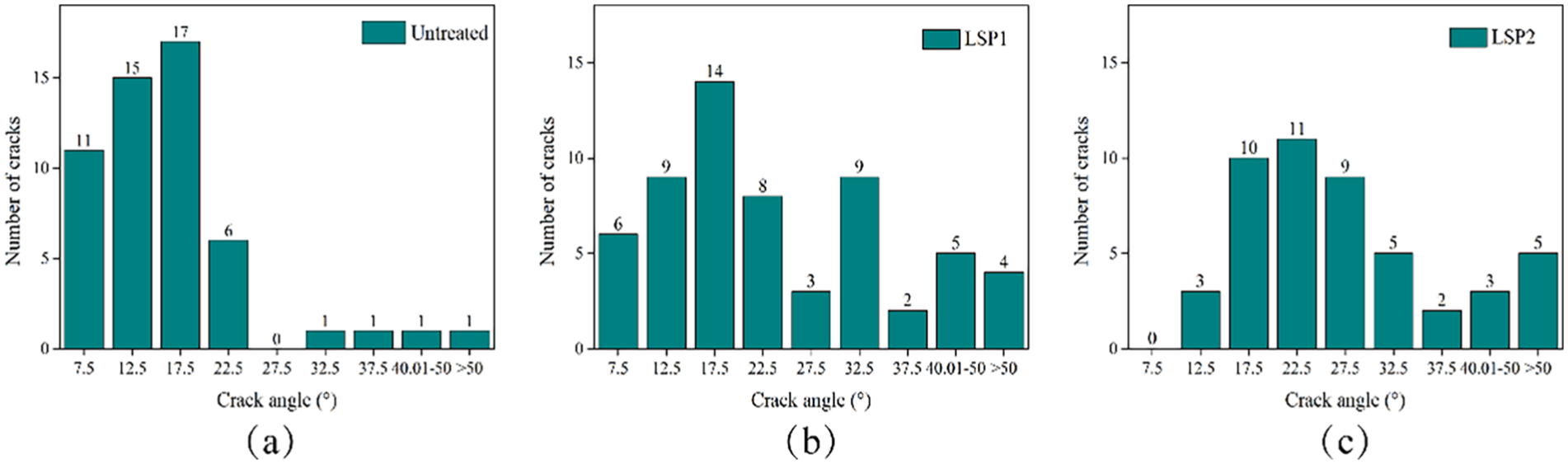
Fatigue crack angle distribution in wheel disks: (a) untreated, (b) LSP1, and (c) LSP2.
Figure 9 illustrates different types of pits-forming process due to different crack inclined angles. It suggests that for short crack with a shallow angle of α, it propagates slightly down into material matrix and quickly turned upward to the surface, resulting in a thin pit. While for an inclined crack with a larger angle of β, the crack propagates longer and deeper into the wheel substrate. The evolution of deep crack propagation is similar to shallow crack, but it takes longer time for crack growth before it turns up toward the surface. This will undoubtedly lead to a deep and large pit. Therefore, it can be inferred that with LSP treatment the surface crack will be inclined at a larger angle leading to deep propagation and finally resulting in larger pits.

Schematic of pit formation due to different crack initiation angles.
Statistical results of crack length on the disk specimen surface at failure are shown in Figure 10. For untreated specimen, the proportion of cracks that were longer than 500 μm was 17%. While this value was 29% and 40% for the specimen treated by LSP1 and LSP2, respectively. Moreover, it can be seen that no cracks longer than 1000 μm can be found in untreated specimen. This result confirms the hypothesis that LSP results in peening effects on the specimen surface, which in turn leads to deeper and longer crack.

Fatigue crack length distribution in wheel disks at failure: (a) untreated, (b) LSP1, and (c) LSP2.
The scanning white light interferometer was used to reveal the pit morphology of disk specimen (Figure 11). The maximum depth of pits on LSP2-peened specimen was 309.8 μm, and it was considerably larger than that of untreated specimen in which the depth was just 182.2 μm. In addition, for untreated specimen, the initial micropitting was shallow, while it was deep for peened specimen. Figure 12 shows the statistical results of pit depth on worn disk surfaces. It can be seen that for untreated wheel specimen, the pit size was relatively small with an average depth of 194 μm. The average depth of pits found in specimen treated by LSP1 and LSP2 was about 223 and 277 μm, respectively. Consistent with the hypothesis shown in Figure 9, larger pits were formed in LSP-treated specimen due to larger crack initiation angle and deep crack propagation path, which results in the longer RCF life.

Typical pit morphology in wheel disks at failure: (a) untreated, (b) LSP1, and (c) LSP2.

Pit depths in wheel disks at failure.
Conclusion
In this study, microstructures and mechanical properties of ER8 ferrite–pearlite steel before and after LSP were investigated. The twin-disk test was conducted to evaluate the effect of LSP on the RCF performance. Microhardness on the ferrite–pearlite steel surface is increased after LSP treatment. The depth of the surface layer affected by laser shock hardening is above 1 mm. Meanwhile, the maximum residual compressive stress generated by LSP on the steel surface is around 1 GPa. The LSP-treated ferrite–pearlite steel disk presents better RCF resistance than untreated one. LSP-induced strain hardening and compressive residual stress alter crack inclination angles and propagation behavior, which results in a longer RCF life.
Footnotes
Handling Editor: José Correia
Declaration of conflicting interests
The author(s) declared no potential conflicts of interest with respect to the research, authorship, and/or publication of this article.
Funding
The author(s) disclosed receipt of the following financial support for the research, authorship, and/or publication of this article: This work was supported by the Joint Funds of the National Natural Science Foundation of China (grant no.: U1834202).