
Abstract
The power system is affected by different levels of transient shock caused by different switching angle when AC filter switching on. The shock causes frequent action and aging of lightning arrester. In this article, the causes of frequent action of lightning arrester in Nuozhadu DC project are analyzed by means of power systems computer aided design simulation. The overvoltage, current, and energy of AC filter switching on are also analyzed. The critical angle of the arrester action of AC filters is discussed. The results show that AC filter switching on can affect this group and other groups. When the closing phase angle reaches 12°, the arrester in this group lightnings. When the closing phase angle reaches 18, the arresters in other groups lightning. Finally, the influence of the three phases and the impact which varies with power are also discussed.
Introduction
High Voltage Direct Current (HVDC) power transmission technology can maximize energy optimal allocation in a wide range and is suitable for energy base to achieve external transmission of ultra-large power capacity and ultra-long distance for asynchronous networking of power system. Therefore, the HVDC power transmission technology plays an important role in the strategic objectives of the national networking and West–East electricity transmission project in China.1–3
AC filter is one of the most important parts in HVDC transmission system whose converter will consume a lot of reactive power in operation and generate a lot of harmonics on the AC and DC sides at the same time. As to compensate reactive power and filter the harmonics on AC side, AC filter with required capacity should be adopted. AC filter needs frequent switching on/off as the DC power varies. When putting the filter into operation, as the voltage and bus voltage on capacitor are not exactly the same, the on–off inrush will be generated in the loop that impacts the system.4,5 At present, most of the AC filters use circuit breaker with phase-selection controller to suppress the inrush6–8 produced during closing.
Literature9,10 have analyzed the problem of phase selection of the AC filter group circuit breaker and discussed the adjustment and debugging method of the fixed value for the phase-selection controller without further analysis of the overvoltage caused by fixed value deviation of the phase-selection controller. Literature11,12 have illustrated the principle of phase-selection controller specially and theoretically calculated the overvoltage when inputting the single group AC filter. However, the calculation result only focuses on the single group rather than the whole AC filter field, and also without a test of the theoretical calculation based on the actual field. Literature 11 points out that there is mutual influence between a set of input AC filters and the AC filters that have been delivered, but there is no detailed analysis of the effect.
At present, there has been no systematic cause analysis report about the abnormalities resulted by low reliability of the phase-selection controller. This article establishes the electromagnetic transient simulation model combined with equipment abnormalities in the Nuozhadu DC transmission project, which calculates the overvoltage when inputting the AC filter, and analyzes the influences of filter’s input time, circuit breaker closing phase, and system transmission power on the overvoltage. Its conclusions can provide theoretical basis for the DC transmission project, especially for phase-selection controller operation and filter design.
Abnormal operating condition of arrester used for AC filter
The Nuozhadu DC transmission project was officially put into operation in 2014, and the C-type (shunt capacitor) AC filter arrester acted too frequently sometimes. The total action of some arresters in the Qiaoxiang station, which is a terminal receiving station of Nuozhadu, has exceeded 1000 times, and some arresters appear downward trend of DC reference voltage. Compared with Yunguang project input in 2009, the difference of C-type AC filter arrester’s configuration and transient overvoltage level in both projects are slight. However, the action of C-type AC filter arrester in the Yunguang project is basically less than 100 times, and the DC reference voltage is also without obvious decrease.
The field monitoring results indicate that the frequent action of arrester in the Nuozhadu DC transmission project is related to the AC filter input, and there is mutual influence between the arresters. The commissioning of one group of filters may cause simultaneous action of multiple groups of arresters at the same time.
Based on the wave recording of phase-selection controller, it is found that the reliability of phase selection is low in average deviation of 2 ms and maximum deviation up to 5 ms. As to make the clear relation between the frequent action reason with closing phase and provide theoretical reference for the operation and maintenance of the equipments, the problem is further analyzed which Taking Qiaoxiang station as an example.
System modeling
Nuozhadu DC engineering system parameter
The normal continuous operation voltage range of AC bus from sending terminal of Pu’er converter station to receiving terminal of Jiangmen converter station in Guangdong ±800 kV ultra high voltage direct current project of Nuozhadu transmission is 500 ∼ 550 kV, the range of normal operation frequency is 50 ± 0.2 Hz, the rated power of DC transmission is 5000 MW, minimum power is 500 MW, rated DC current is 3.125 kA, and rated DC voltage is ±800 kV.
There are two types of AC filter groups in Qiaoxiang station: (1) double-tuned filter DT11/24 (A-type, four groups) and DT13/36 (B-type, three groups), and (2) shunt capacitor (Shunt C, C-type, seven groups totally). Wire connection is shown in Figure 1, and the configuration of group filter is shown in Table 1.

Connection diagram of filters: (a) double-tuned filter and (b) shunt capacitor.
Group filter configuration.

Simulation model
The establishment of the Nuozhadu DC project power systems computer aided design (PSCAD) simulation model is shown in Figure 2. The project contains four groups of A-type, three groups of B-type, and seven groups of C-type AC filter. The arrester equipment parameters are shown in Table 2. Each of sending and receiving stations contains two poles, and each pole contains two 12-pulse converter units. The simulation model voltage becomes stable when it is around 0.3 s. Therefore, the input operation of the filter is set to about 0.4 s, and the total simulation time is set to 0.5 s, which is combined with the transient time after shutdown.12,13

±800 kV Nuozhadu DC transmission project model.
AC filter arrester parameters (kV/kA).

Model verification
As to verify the accuracy of the model, the wave recording under a working condition in the field has been compared with the simulation result. It should be noted that the main research object of this article is the action of arrester, and the peak voltage is used as the criterion for judging whether arrester is in action or not. So only peak voltage is compared between measurement and simulation result as shown below.
The reactive power control at a certain time requires the input of 591 C-type AC filter. At this time, the DC transmission power is 4862 MW, and the filter working condition is 4A + 3B + 2C. The current waveform after three phases of 591 filter connecting is measured in Figure 3. Curves 1, 2, and 3 are bus voltage waveforms which still exist, and Curves 4, 5, and 6 are three-phase current of 591 filter which starts at the closing moments of breakers. Take the A phase as an example: the current peak at 591 bus is about 3.5 kA.

Waveform of 591 AC filter switching on.
The simulation model is used to calculate the above operating conditions. After obtaining 591 input, the simulation result of phase current waveform is shown in Figure 4 and the current peak value is 3.7 kA.

Simulated current waveform of 591 phase A.
Under the same operating conditions, the relative error between simulation result and actual measurement is 5.7%, which indicates that the simulation is credible.
Simulation result analysis
Analysis of the most serious working conditions
Referring to the AC filter input strategy, the most severe working conditions under the bipolar full voltage operation mode are as follows: when inputting the four groups of filters totally, the last group of C-type filters was input when one phase is ahead of 90°. Take 571 filter to be the filter to analyze the 571 (C-type), 572 (C-type), 573 (A-type), and 574 (B-type) connected on the #7 bus.
When 571 filter was input, we analyze the overvoltage of the 571 and 572 arresters. It can be seen from Table 3 that when 571 filter was input, the transient current amplitudes of this group and 572 group of arresters are more than 0.03 kA (criteria for arrester action) and the arrester acts. When 571 filter was input, the amplitude and voltage amplitudes of the 573 and 574 arresters all have different degrees of changes, as shown in Table 4. The following definitions are given: F1—type arrester of 573 filter is named as 5731, F2—type arrester of 573 filter is named as 5732, and other filter groups are the same.
The arrester parameters of 571 and 572 (kV/kA/kJ).

The arrester parameters of 573 and 574 (kV/kA).

It can be seen from Table 4 that when 571 filter was input, the instantaneous currents of 5731 and 5741 arresters are 0.03 kA higher than the counter action current, and 5732 and 5742 arresters do not act. The action of arrester is caused by closing inrush impact, and the current monitoring of different filters is shown in Figure 5. It is known that at the moment of 571 filter input, the currents of each group of filters have all increased, and the current amplitude of 571 filter exceeds 10 kA, which is the most serious. The current amplitude of 572 filter reaches 1.5 kA, the current amplitude of 573 filter reaches 0.5 kA, and the current amplitude of 574 filter reaches 0.7 kA. The current growth of the filter is consistent with the arrester action.

The currents of each group of filters in #7M.
The effect of closing phase
Input of C-type filter
Taking the 571 group A phase in full power operation as an example, the overvoltage and overcurrent level of closing phase change every 15° within 0° ∼ 90°, shown in Figures 6 and 7.
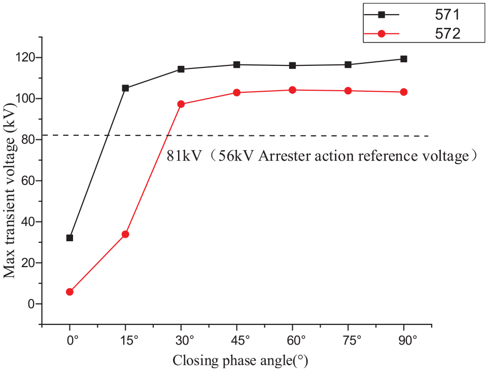
The effect of closing phase angle on voltage amplitude.
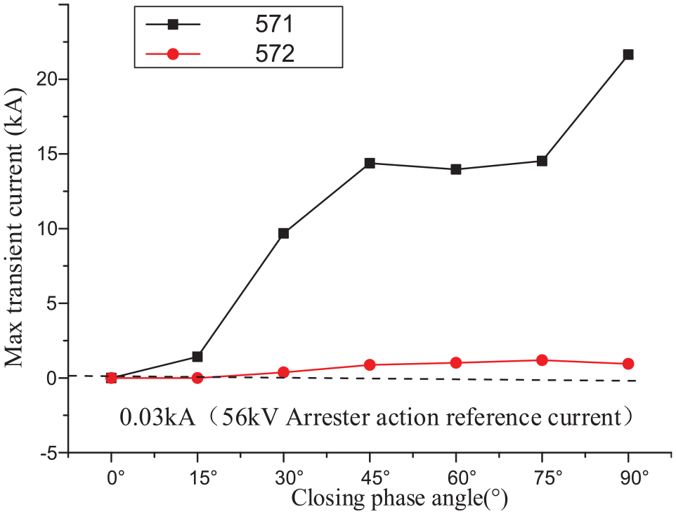
The effect of closing phase angle on current amplitude.
From Figures 6 and 7, it can be seen that the voltage and current amplitudes of 571 and 572 group arresters increase gradually with the increase of closing phase angle, and the amplitudes of 571 group arresters increase more obviously. In addition, the instantaneous current of 571 arrester exceeds 0.03 kA when closing phase angle is 0° ∼ 15° ahead, and the arrester acts. When the closing phase of 571 is 18° ahead, 572 arrester starts to act.
To further determine the critical angle of the 571 action, the simulation is continued at within 0° ∼ 15°, as data shown in Table 5. When closing phase is 12° ahead, the instantaneous current of 571 arrester exceeds 0.03 kA, and the arrester starts to act.
Voltage and current of 571 arrester (closing phase 0°–15°).

Input of A- and B-type filters
Similarly, taking the 562 group A phase running by 2A + 1B as an example, the closing phase changes within 0° ∼ 90°, and the specific situation is no longer described, which obtains the following conclusions: the voltage and current amplitudes of 562 group arrester are growing with closing phase angle increase. When the closing phase is about 14°, the instantaneous current of 5621 arrester exceeds 0.03 kA, and the arrester starts to act. When the closing phase is about 27° ahead, the instantaneous current of 5622 arrester exceeds 0.03 kA, and the arrester starts to act.
Influence between different phases
As to verify whether different phases will interact with each other due to the change of closing angle, the influences of simulation for closing phase change of phase B on other two phases under working condition of full voltage power are as follows: (1) A phase shifts 90°, B phase and C phase do not shift; (2) A phase shifts 90°, B phase shifts 30°; C phase does not shift; (3) A phase and B phase shift 90°, and C phase does not shift. The peak voltage of arrester is recorded, as shown in Table 6.
Effect of closing phase of phase B on the other two phases.
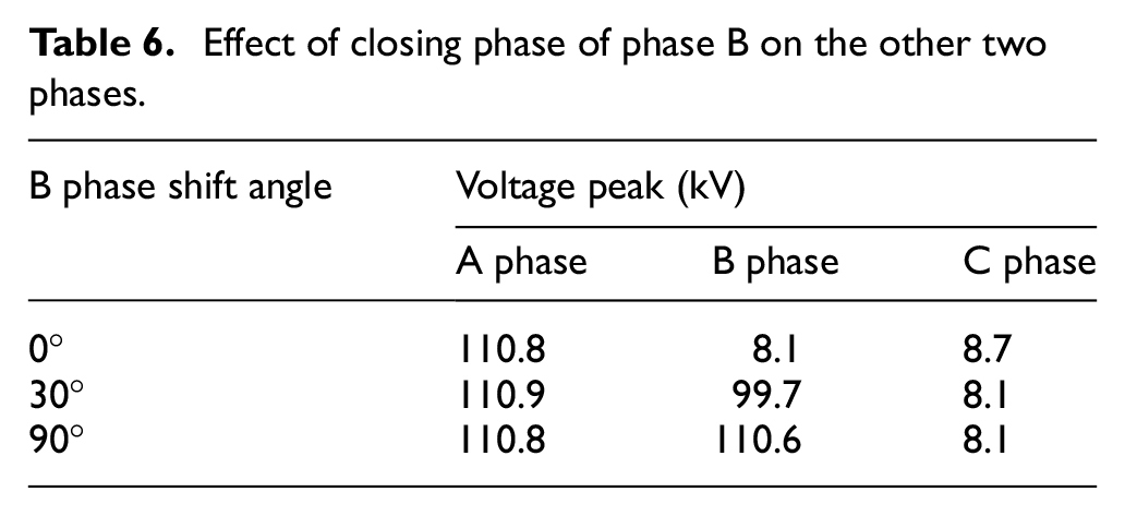
From Table 6, we can see that when the closing angle of B phase changes from 0° to 90°, the voltage peak value will change without influencing voltage peaks of the A and C phases. Therefore, it is believed that there is no interaction between different phases, and they are independent.
Influence of operation mode
Change of arrester’s voltage, current, and energy with the power
Table 7 lists the corresponding relation between the transmission power and the number of some AC filters in Qiaoxiang station. As frequent action are mainly from the C-type filter arrester, the simulation analysis only considers different power levels within 4000 ∼ 6250 MW. The group number of input filter is as follows: A-type and B-type are totally input and the C-type running groups are increased to 5 from 0. Various indicators of all arresters in #7M when 571 filter input is analyzed as below.14–16
AC filter delivery strategy.

When 571 filter switches on at the closing phase of 90°, the arrester action is shown in Table 8. The change of voltage and current energy of the arrester with the power is shown in Figure 8, which can obtain the following conclusions: when system transmission power changes from 4000 to 6250 MW, the 571, 572, and 5731 arresters all act. The 5741 arrester acts below 5000 MW, and no arrester will act in other situations. With the increase of transmission power, the peak voltage and energy of the 571 group arrester rise gradually, and the voltage and energy of other arresters all decrease.
AC filter arrester action in #7M.

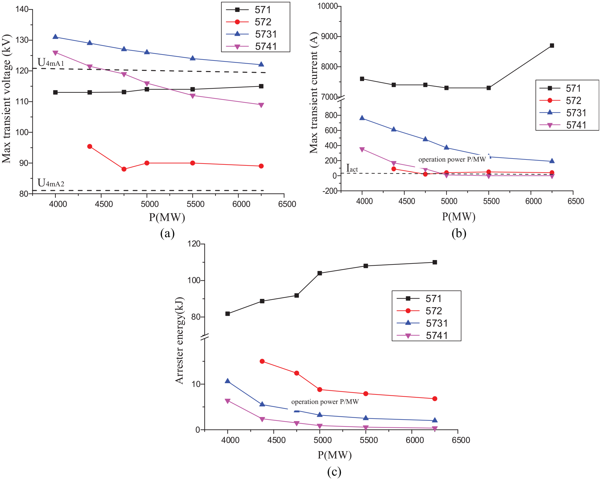
The voltage, current, and energy of the arrester: (a) voltage change trend of each moving arrester, (b) current change trend of each moving arrester, and (c) energy change trend of each moving arrester.
Critical angle of arrester action in each type
When the transmission power changes from 4000 to 6250 MW, the critical angle of closing for each arrester, and the result is shown in Figure 9. We can see that the action critical angle of the C-type filter decreases with the power increase, and the action critical angle of A-type and B-type filters increases with the power increase.

Influence of power on the phase angle.
Conclusion
Switching on of group filters at the converter station may cause different levels of transient impact on the system and frequent action and aging of the arrester. Simulation results indicate switching on of the AC filter may produce impact in its own group filters and other group filters. As the closing phase of C-type filter is 12°, the arrester of the own group filters acts, while when the closing phase is 18°, the arrester of the other group filters acts. The action critical angle of C-type filter decreases with the power increase, and the action critical angles of A- and B-type filters increase with the power increase. To make sure the AC filter arrester does not act, the closing phase must be less than 12°, which means that the error of phase-selection controller must be controlled within 0.7 ms.
Footnotes
Handling Editor: Yanling Wei
Author note
Xin Luo is now affiliated with Faculty of Electric Power, South China University of Technology, Guangzhou, China.
Declaration of conflicting interests
The author(s) declared no potential conflicts of interest with respect to the research, authorship, and/or publication of this article.
Funding
The author(s) received no financial support for the research, authorship, and/or publication of this article.