
Abstract
With the development of High Voltage Direct Current (HVDC) and ultra HVDC, a growing number of high voltage film filter capacitors have been installed for harmonic suppression. But the capacitors generate severe audible noise in the converters, which has become more and more serious. Then it is important to imitate the practical working situation of capacitors for the research of noise characteristics to improve the capacitive performance in lab. In this paper, a FFT-based harmonic current control method is proposed for audible noise analysis of AC filter capacitor. Firstly, mathematical model of the Harmonic Current Injection System (HCIS) is built based on MATLAB. Then a Fast Fourier Transform (FFT) harmonics detection method is analyzed and used to detect the amplitude and phase of each harmonic considering a number of harmonic currents flowing through AC filter capacitors. Since the amplitude and phase spectrum of capacitor current are obtained, the Proportional Integral (PI) regulator is applied to adjust the specified harmonic amplitude to achieve zero-error control. Then accurate harmonic current can be injected to the tested capacitor and it will help to acquire the noise characteristics of the tested plant. At last, the simulation and experimental results validate the proposed strategy.
Introduction
With the increasing of energy demand and the development of new energy generation technology, HVDC transmission technology becomes to one of the development directions of power grid in the future in order to supplement the existing AC transmission system. The technology has significant advantages in long-distance, high-volume power delivery, and interconnection of the modern power grids. 1 Among them, converter station is the key part of HVDC transmission system, and a large number of low-order harmonics are generated. In order to compensate reactive power and filter harmonics, the converter station needs a large number of AC filter capacitors which will generate audible noise. With the application of HVDC technology, the problem of noise pollution in converter station has becomes more and more serious. The audible noise created by AC filter capacitors in converter station may be over 100 dB (A) when capacitor currents contain multiple harmonics. 2 The audible noise of AC filter capacitors is mainly caused by harmonic or superposition of harmonics, in which 11th and 13th harmonic currents produce the most serious noise. When harmonic currents flow through the internal of capacitor, it will cause the vibration of capacitor inner core, and finally, the vibration can transfer from the inside to capacitor cases to produce the noise.
In the last decade, many scholars have been focusing on the audible noise characteristics of capacitors and noise suppression. Li et al. 3 and Cox and Guan 4 have investigated the relationship between the audible noise and the vibration characteristics. The acoustic noise of AC filter capacitor is affected by the attributes of harmonic currents, such as the amplitude, relative phase, and the harmonic order. 5
Unfortunately, due to the limitation of the working condition, it is impossible to analyze exactly the acoustic noise characteristics on site. So, a test bench, which could simulate the practical work circumstance of the capacitors, is necessary in laboratory. Then the relatively accurate noise characteristic of capacitor can be acquired and the results can be used to improve the capacitor.
For the sake of the adequate implementation of this work, two main parts are vital important: (1) harmonic detection algorithm to get the specific attributes of harmonic currents (frequency, phase, and amplitude) and (2) harmonic current controller to regulate the amplitude to meet reference.
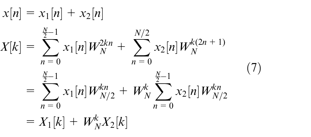
For now, numerous harmonic detection algorithms have been proposed. In general, those algorithms fall into two categories: time-domain methods and frequency-domain methods.
Time-domain harmonic detection methods are based on the instantaneous reactive power theory, such as p-q method6,7 and d-q method.8,9 In addition to the instantaneous reactive power, the filter algorithms have to be used to separate the fundamental and harmonic components, such as Adaptive notch filter (ANF) 10 or Kalman filter. 11 There has a common feature about the time-domain harmonic detection algorithms: after a number of mathematical manipulations, the harmonic components are obtained by the use of the corresponding filter. To a great extent, the filter determines the performance of the harmonic detection algorithm. As a result, the time-domain harmonic detection method can compute one harmonic component rapidly. But the computation burden of this detection algorithm will be greatly increased with the increase of injected harmonic number. Moreover, multiple filters used in time-domain can also increase the computational burden of the system considering that each harmonic needs a unique filter.
The frequency-domain harmonic detection algorithm is more appropriate for this work compared to time-domain methods because the phase and amplitude information of all harmonics can acquired during one calculation procedure. The these methods originate from the Fourier transform, such as DFT, 12 FFT, 13 and SDFT. 14 FFT is an efficient way to implement DFT. And it can decompose an N-point DFT into two N/2-point DFT to accelerate the operational speed and reduce the operation burden.
In this paper, in addition to detect the harmonic currents exactly, regulation of the harmonic current is also an important task. In time domain, with the conversion of specified harmonic into DC component, PI controller for each harmonic can be designed to realize zero steady-state error tracking control.15,16 According to the Internal Model Principle, 17 the Proportional Resonant controllers can also be used to control the AC reference components. Besides the above linear controllers, some nonlinear controllers have been applied to harmonic control, such as Model predictive control (MPC), Repetitive control (RC) and Sliding Mode control (SMC), etc.15,18–20
Since the amplitude spectrum extracted by FFT algorithm is DC component, the discrete PI regulator can also be used to track the reference amplitude with zero steady-state error. On the other hand, the system inherent delay would result in the phase deviation, caused by the digital sample delay and system impedance. And the phase deviations will be more serious with the increase of harmonic order. 21 Thus, the phase deviations should be compensated separately for each harmonic to ensure the performance of the overall system. Once the amplitude of harmonics is detected and controlled, and the phase deviations are compensated, the reference signal can be reconstructed on the time field with Inverse Fast Fourier Transform (IFFT). Then the output reference is converted into analog signal by digital to analog converter.
In this paper, FFT-based selective harmonic current control is proposed for research on audible noise characteristics of AC capacitors. Firstly, in section 2, the mathematical model of HCIS is presented. In section 3, a detailed presentation about the detection and control strategy for harmonic currents will be given. Finally, the simulation and experimental results of the HCIS based on FFT are shown in section 4 and 5, based on the MATLAB/Simulink and RT-LAB, respectively, to validate the significance of the proposed strategy.
System configuration
Harmonic currents injection system
The HCIS shown in Figure 1 is composed of the reference signal generator, harmonic detection module and current controller, transformer, tested capacitor, and switch mode power amplifier. The fundamental and selected harmonic signals are all generated by the reference signal generator with the specific parameters such as the frequency, amplitude, and phase angle. The switch mode power amplifier can amplify the input signal linearly. And the amplified harmonic voltage can be injected into the power capacitors by the transformer.
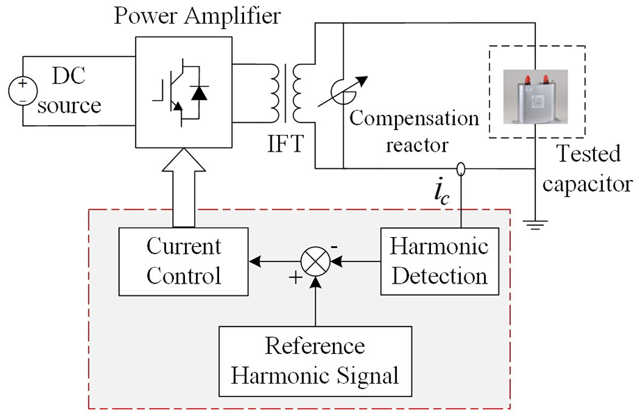
Harmonic currents injection system.
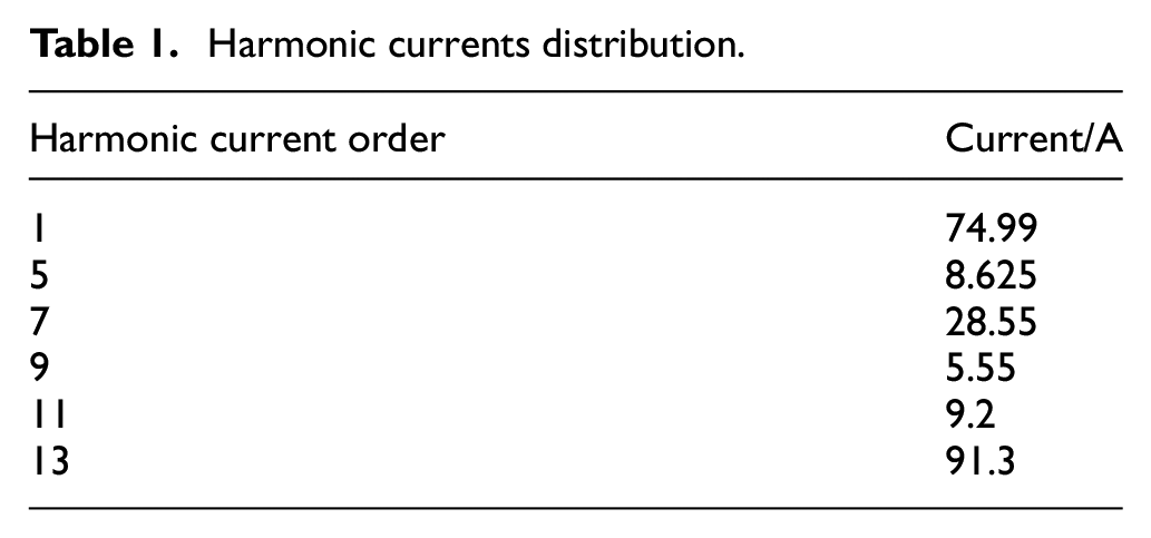
The capacitor harmonic currents in HVDC converter station vary greatly under different working conditions. One of the actual measured harmonic currents of power capacitor (6.2 kV/38.5 uF) in one converter station is shown in Table 1. It can be found that the 13th harmonic is 91.3 A which will cause serious audible noise.
Harmonic currents distribution.
Model of the HCIS
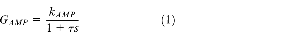
The power amplifier with inner voltage control can be approximately considered as a first-order inertial link, and its transfer function is expressed as:
where
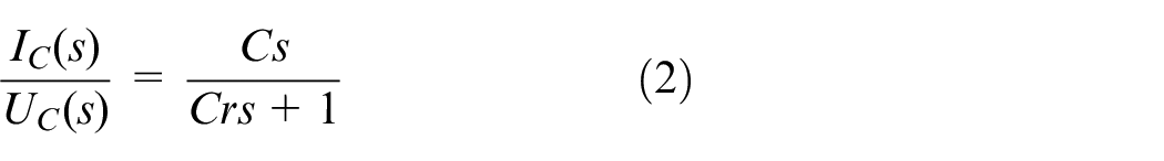
The capacitor is simplified as an ideal capacitor C with an equivalent resistor
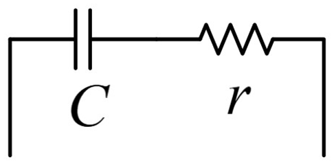
The simplified capacitor model.
The transfer function of the output current
Harmonic currents detection and control strategy
Harmonics detection algorithm
In this section, the principles and processes of FFT detection algorithm will be presented in detail. FFT algorithm is an efficient method for DFT calculation, and DFT is the discrete Fourier analysis with finite length.
If a periodic and continuous signal
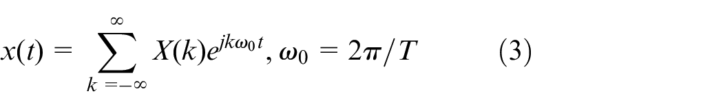
where T is the period of the signal. In real control system, the signal both in time and frequency is discrete and has limited sample length, thus N-point DFT is realized with a sampling rate
where
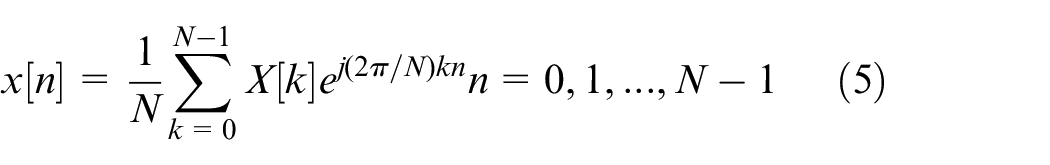
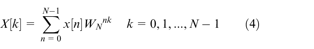
Usually, an N-point DFT operation requires
By the aid of the mathematical characteristics of the twiddle factor, the FFT algorithm decomposes the N-point DFT into smaller DFTs to reduce the computational burden of DFT.
As shown in Figure 3, every point means a complex addition and arrows mean complex multiplication. The N-point FFT will be transformed into two N/2-point DFTs according to recursive decomposition, then the N/2-point DFT will be transformed into the N/4 DFTs. This operation will be repeated, until the final 2-point DFT is extracted.
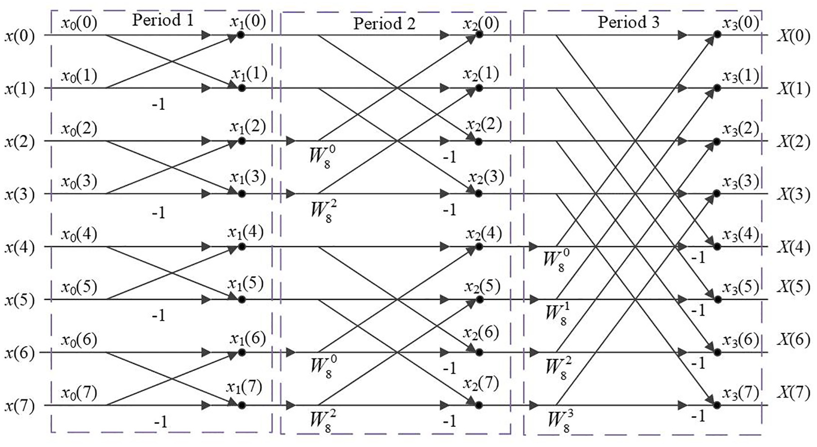
Principle of 8-point FFT algorithm.
Generally, the decomposition number of an N-point FFT is
Take the DIT-FFT for example,
where
As shown in Figure 4, this basic operation unit of FFT is called butterfly operation.
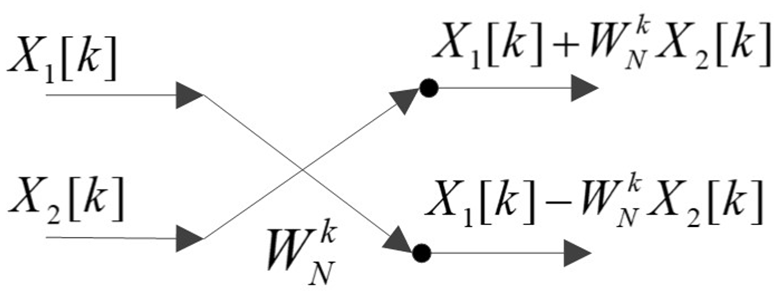
Butterfly operation.
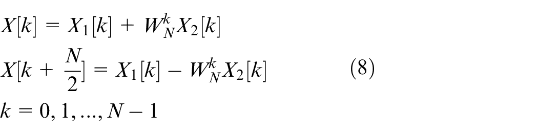
All this leads up to the basic principle of FFT: a long sequence of DFT can be transformed into two short sequences of DFT by properties of DFT. The computational complexity of N-point FFT is
In the rest of this paper, some features about the spectrum will be shown. It is clear that the output elements of FFT would be limited to the number of N. And the frequency resolution is
For the N complex numbers obtained by FFT, the frequency of the first item is
If an exact integer period of signals is included during the sampling window at the signal acquisition stage, the final results of FFT algorithm will be precise. The well-known result of “harmonic leakage” is caused by incompleteness within the data acquisition window, and the harmonics “leakage” will result in the inaccurate detection. Under these circumstances, some relevant measures have been proposed to compensate the impact of non-cycle sampling, such as: adding the window function or zero padding.
When the amplitude and phase angle of a specific harmonic are extracted from the data frames, the corresponding harmonic current regulator will be adopted to ensure the accurateness of the amplitude, and the related phase compensation angle is applied to ensure the synchronization. When the specific harmonic current has been controlled, the instruction signal can be obtained again in time domain by IFFT or other reconfiguration algorithms.
In general, the number of input and output points of FFT algorithm is equal. To reduce the computational burden, some specific points such as X(3), X(5), and X(7) are selected for calculating the specified butterfly of FFT.
Harmonic control method
The configuration of the proposed HCIS is shown in Figure 5. The tested current measured by hall sensor is converted to digital data with the help of AD converter. Then the magnitude and phase of a specific harmonic current are detected based FFT method. And a PI regulator for specific harmonic is used to track the reference with phase compensation. At last, the reference signal for power amplifier is reconstructed in time domain by IFFT.
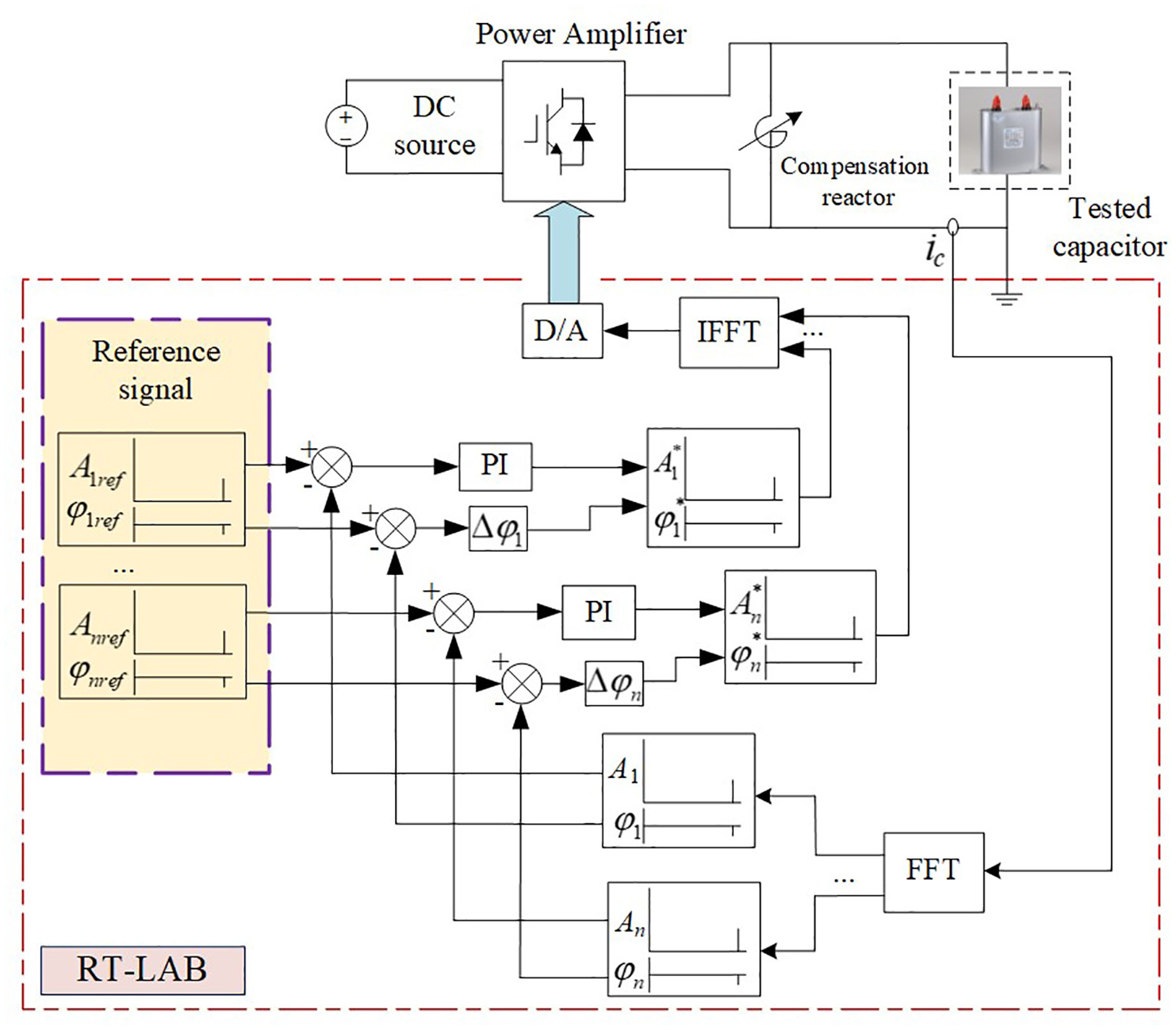
Configuration of the proposed HCIS.
A PI regulator is applied to control the harmonic current amplitude to achieve zero-error control. 22 The transfer function of PI controller for the fundamental current is expressed as:
where
Let
where
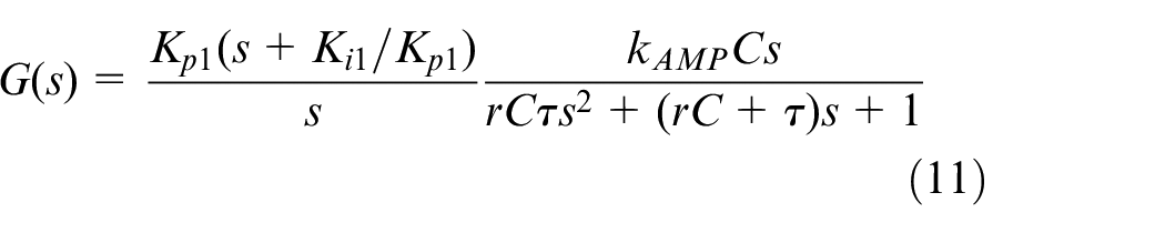
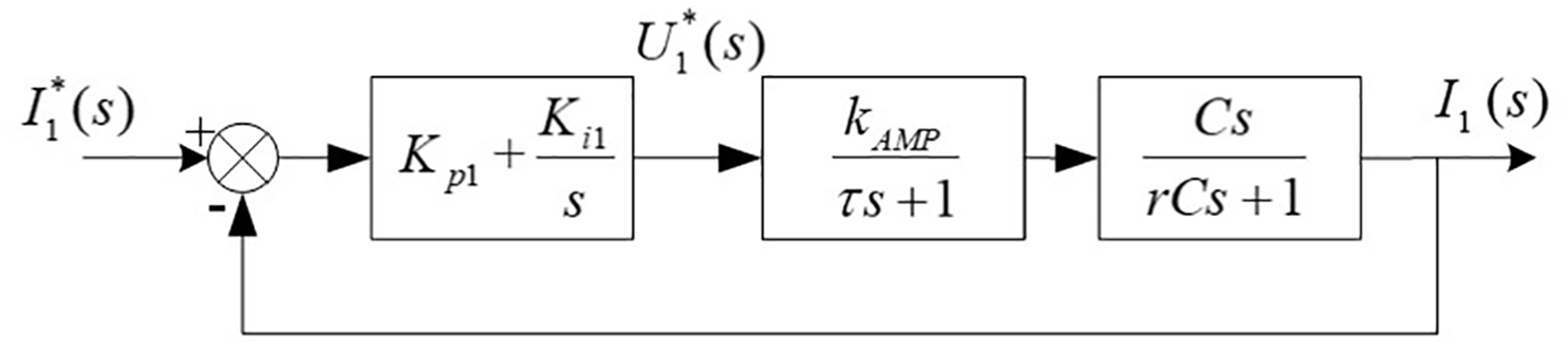
Current closed-loop control model.
Based on the open-loop transfer function (11), suitable cross frequency and phase margins are selected to meet the requirements of robustness and dynamic response. Then the values of the
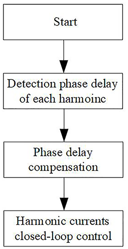
Considering the influence of the system inherent delay, such as the delay of AD, DA, and power amplifier, the phase deviation of each harmonic should be tested and compensated for control. A phase compensation is needed in this system to eliminate the impact of the deviation. Assuming the system parameters are generally invariant during the testing process, the angle offset of a specified harmonic order is basically constant. Thus, a preprocessing procedure can be used to detect the phase deviation of the relevant harmonic order.
Figure 7 shows the operation flow char of the system. In the pretreatment segment, the phase delay of a given harmonic is detected and the angles is stored for the future experiments. Finally, the phase compensation can be directly used in the reference spectrum.
Operation flow chart of HCIS.
Simulation results
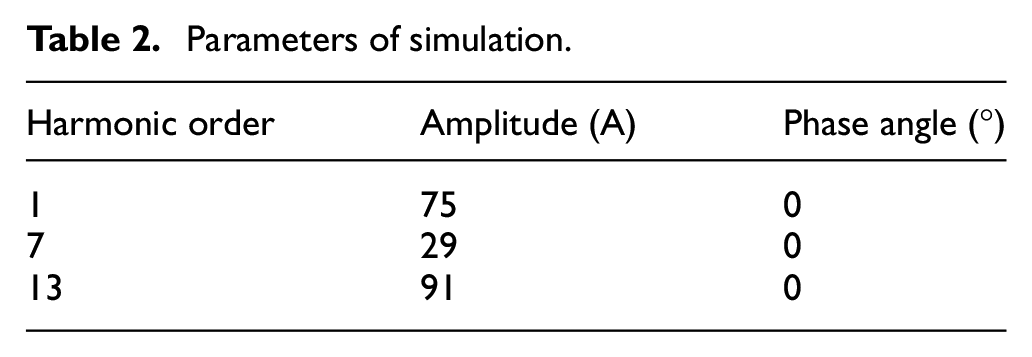
In order to verify the effectiveness of the harmonic current detection and control strategy of the proposed HCIS, simulation model has been built based on MATLAB/Simulink. Table 2 shows the harmonics reference. The current is sampled with 2560 Hz sampling rate, and 256 points are used for FFT calculation. The frequency resolution ratio of this detection is 10 Hz, so the frame has integer number of cycles, and the spectrum leakage can be avoided. Figure 8(a) shows the current waveform of tested capacitor. As shown in Figure 8(b), the fundamental current is 75.01 A, the 7th harmonic is 29.0 A and the 13th harmonic is 90.99 A. It can be found that the harmonic components of the injected current are consistent with the reference current values shown in Table 2.
Parameters of simulation.
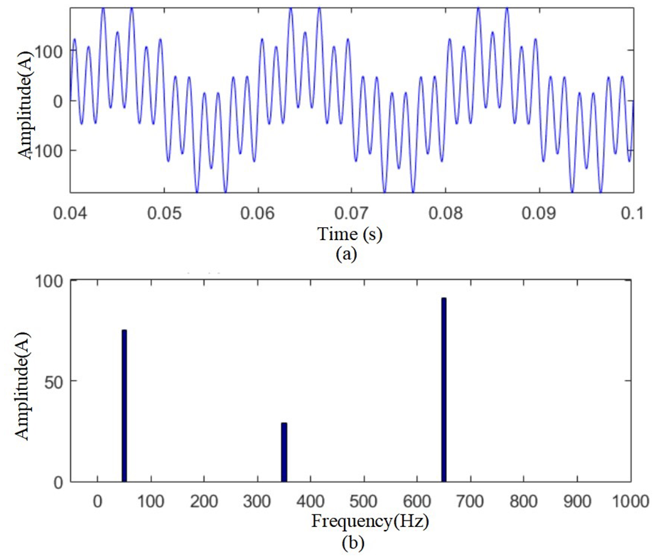
Simulation results: (a) current waveform of the tested capacitor and (b) harmonic spectrum of injected current.
Experimental results
In this section, experiments about HCIS are carried out based on the RT-LAB platform. The RT-LAB developed by Opal-RT Technologies has been widely employed in various domains. RT-LAB software can immediately compile and import mathematical model built with MATLAB/Simulink into real-time simulation platform for control and test. It is equipped with 16 channels for 16-bit ADC and the input ranges up to ±20 V. It also has 16 channels for 16-bit DAC and the output ranges up to ±15 V. The gap between the simulation clock and natural clock is only nanoseconds.
The experimental test bench is shown in Figure 9. Due to the limits of power level in lab, the transformer is not used and the compensation reactor is applied to reduce the active output power.

Experimental test bench.
In this system, considering the sampling delay and the calculation burden of FFT algorithm, the sampling points is 1280 points and the model step size is 1/12,800. Table 3 shows the critical experimental parameters of HCIS. Both the harmonic current detection and control algorithms are implemented on the RT-LAB. And the variable quantities of the system can be set in real time in the host computer.
Experimental parameters of HCIS.
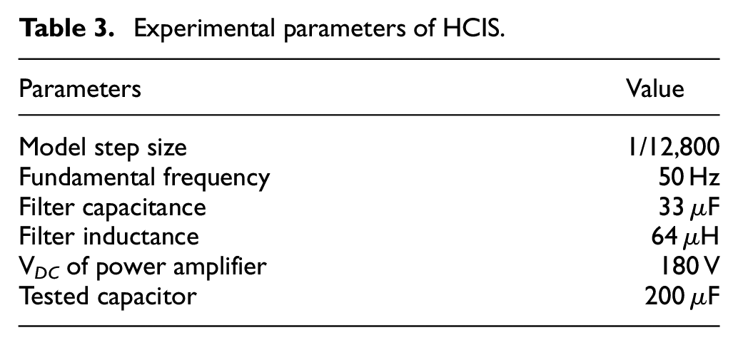
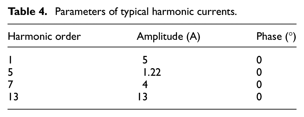
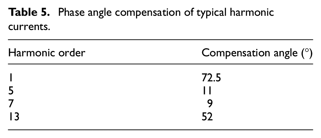
Table 4 shows the parameters of several typical harmonic currents, which can be regarded as the reference values of HCIS. And the compensation phases for different harmonic orders can be calculated in the pre-processing stage, which are shown in Table 5.
Parameters of typical harmonic currents.
Phase angle compensation of typical harmonic currents.
After the phase compensation, the system can work normally with the harmonic current control strategy. As a comparison, Figure 10 shows the reference harmonic current waveform of the system. The injected harmonic current flowing through the tested capacitor is shown in Figure 11. The actual current is the same as the reference current. The spectrum of the injected harmonic current is calculated in Figure 12. As shown in Figure 12, the fundamental current is 5.02 A, the 5th harmonic is 1.21 A, the 7th harmonic is 4.01 A, and the 13th harmonic is 12.98 A. It can be found that the harmonic components of the injected current are consistent with the reference current values shown in Table 4. Therefore, the injected harmonic current generated by the proposed HCIS can meet the requirements of audible noise testing for AC filter capacitors.
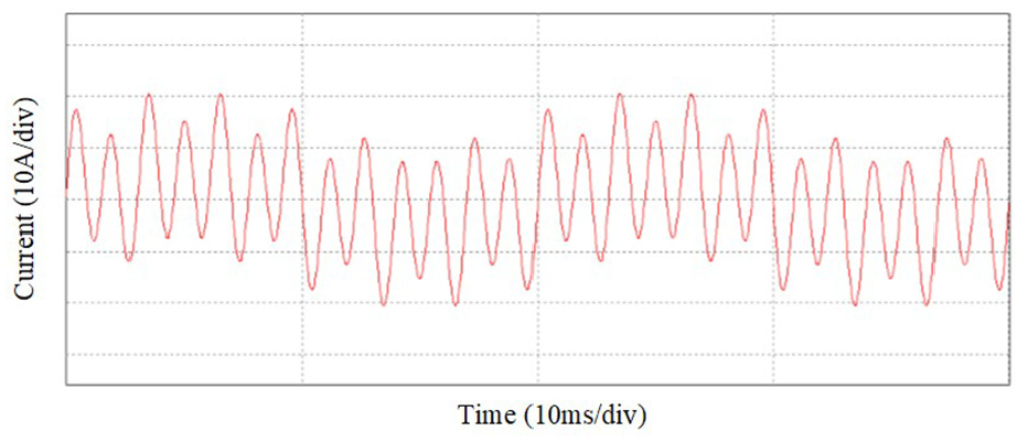
Reference current waveform of the system.
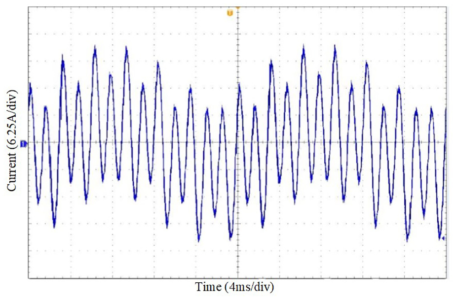
Injected current waveform of the tested capacitors.
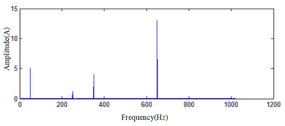
Spectrum of the injected harmonic current.
Conclusion
In this paper, a FFT-based selective harmonic current control is proposed and applied to a HCIS, which can simulate the actual working conditions of AC filter capacitors in a converter station and help to analyze accurately the audible noise characteristics of AC filter capacitor in laboratory.
The theoretical analysis about harmonic detection algorithm based on FFT is presented and analyzed. Although the frequency leakage problem of FFT algorithm will affect the accuracy of measurement due to aperiodic sampling and cutting off sampling. This problem is not affecting so much. Since the amplitude and phase of each harmonic can be determined during one calculation procedure, the PI controller is designed to regulate the harmonic amplitude. A preprocessing procedure is applied to detect and compensate the angle offset. Once the amplitude of harmonics is detected and controlled, and the phase deviations are compensated, the reference signal can be reconstructed on the time field with IFFT and be used to control the power amplifier. Then the desired harmonic currents can be injected into the tested capacitor. The simulation and experimental results validate the proposed strategy.
Footnotes
Declaration of conflicting interests
The author(s) declared no potential conflicts of interest with respect to the research, authorship, and/or publication of this article.
Funding
The author(s) disclosed receipt of the following financial support for the research, authorship, and/or publication of this article: This research is supported by National Natural Science Foundation of China (Project Number:61673260)