
Abstract
A one-way fluid-to-acoustic coupling approach which combines the computational fluid dynamics and the acoustic finite element method is employed to predict the acoustic attenuation performance of perforated silencers in the presence of non-uniform flow. This technique ensures that the convective and dissipative effects caused by fluid flow on the acoustic attenuation performance of perforated silencer can be taken into account. The comparisons between the numerical predictions and the previously published experimental measurements show the reasonably good agreements. The acoustic attenuation predictions of perforated silencers without and with flow show that (1) the effect of grazing flow on the acoustic attenuation of the straight-through perforated tube silencer is obvious at higher frequencies, while marginal in the low frequency range; (2) the bias flow enhances the acoustic attenuation performance of perforated silencers at most frequencies; (3) the grazing-bias flow reduces seriously the first resonant peak of three-pass perforated tube silencer and increases the acoustic attenuation in specific frequency range; and (4) when the grazing-bias flow in the orifices of perforated tube and bias flow in the orifices of perforated bulkheads exist simultaneously, the latter plays a leading role to the acoustic attenuation performance of three-pass perforated silencers.
Keywords
Introduction
Perforated silencers are a highly desirable component to reduce the intake and exhaust noise. To meet the needs of high noise attenuation in the wide frequency range or specific frequency band, various structures with single or multiple-passage of flow are presented, such as straight-through, flow-plug, two-pass and three-pass perforated tube silencers.
In order to predict the acoustic attenuation performance of silencers, one-dimensional (1D) methods were developed. However, the methods are suitable only in the plane wave region. Three-dimensional (3D) methods such as finite element method (FEM) and boundary element method (BEM) consider the effect of 3D waves inside the silencers, so are suitable for the acoustic attenuation prediction and analysis in wide frequency range or at higher frequencies. 1 Ji and Fang 2 employed FEM/BEM to predict transmission loss (TL) of silencers using the acoustic impedance of perforation. This technique avoids spatial discreteness in perforated parts and reduces the degree of freedom of computation. However, it excludes the effects of flow on the acoustic attenuation performance of silencers.
It is well known that two factors can occur in the perforated silencers with flow: the convective effect and the dissipative effect of perforation. In order to investigate the both effects of flow on the acoustic attenuation performance of perforated silencers, more accurate predictive methods need to be explored.
Fan and Guo 3 employed commercial computational fluid dynamics (CFD) software ANSYS Fluent to calculate the mean flow field inside silencer and then put it into the acoustic field to determine the acoustic attenuation performance by solving the convected wave equation. However, they neglected the change of the acoustic resistance of perforation with various flow velocities and all acoustic domain including the orifices were meshed, which leads to (1) neglecting the dissipative effect of perforation caused by local flow and (2) huge computation cost.
Broatch et al. 4 presented a 3D time-domain method based on the CFD simulation of an impulsive test to compute the TL of a simple expansion chamber and a reversing chamber muffler. Their numerical predictions agree fairly well with measurement in the absence of flow. However, the TL in the presence of flow is not validated with experiment. Liu and Ji 5 extended the time-domain CFD method to predict the acoustic attenuation performance of perforated tube silencers without and with flow. Their predictions agreed well with the measurements. To capture the orifices’ shape, the minimum size of CFD mesh is usually less than 1 mm, so that CFD simulation needs small enough time steps to meet the requirements of Courant number. The huge computation cost makes that the 3D time-domain CFD method is not suitable for practical design of silencers.
According to the angle between flow direction and axial direction of orifices, it can be simply divided into two kinds, for example, grazing flow and bias flow. Lee and Ih 6 found that the predicted results using the previous empirical model of peroration showed a large discrepancy with the measured results in some cases. Using the measured data of various structural parameters, frequencies, flow velocities, and other factors, the empirical formula of acoustic impedance under grazing flow conditions was fitted. Although it was more comprehensive than previous studies, there was still some discrepancy in the TL predictions and measurements. Alternative choice is to employ numerical method to calculate the acoustic impedance of perforation. Kang et al. 7 investigated the effect of grazing flow on the acoustic impedance using CFD time-domain method. Their empirical formula showed good suitability in the acoustic attenuation prediction of straight-through perforated tube silencers. Most of experimental data and empirical model showed that a grazing flow increase the acoustic resistance and decrease the acoustic reactance of perforation. In the presence of bias flow, Sullivan 8 discussed the acoustic impedance of perforation of flow-plug perforated tube silencers. The acoustic resistance increase as increasing of flow velocity in the orifices and the relationship is linear basically. By comparing the TL predictions of the silencer using the acoustic reactance of perforate in absence of flow and neglecting acoustic reactance, Sullivan suggested that the effect of bias flow on acoustic reactance of perforation may be neglected.
In fact, the both grazing flow and bias flow exist in most perforated silencers. Dean and Tester 9 pointed that the effect of grazing flow on acoustic impedance can be neglected while the ratio of bias flow velocity to grazing flow velocity is larger than 0.3. More comprehensive study of grazing-bias flow has been carried out by Sun et al. 10 The square of effective discharge coefficient they proposed is inversely proportional to the acoustic resistance.
In order to consider the both effects of flow on the acoustic attenuation performance of perforated silencers, a one-way fluid-to-acoustic coupling approach is proposed in this article. Through obtaining the flow velocity data by CFD simulation, acoustic impedance of perforation could be evaluated by empirical formulas. Then the convected wave equation is solved numerically to determine the sound field inside the silencer. Another objective of this study is to investigate the acoustic attenuation performance of three-pass perforated tube silencers in the presence of flow. This article is also a continuation of our previous work, 11 which discussed the effects of various perforation configurations on the acoustic attenuation performance of three-pass perforated silencers in the absence of flow.
Following this Introduction, section “One-way fluid-to-acoustic coupling approach” describes one-way fluid-to-acoustic coupling approach. Experimental validation is presented in section “Experimental validation.” Section “Flow effect on the acoustic attenuation performance of silencers” exhibits the flow effect of perforation on the acoustic attenuation performance of three-pass perforated silencers, followed by concluding remarks in section “Conclusion.”
One-way fluid-to-acoustic coupling approach
Simulation process
Figure 1 shows the process of one-way fluid-to-acoustic coupling approach. The flow velocity inside silencer is calculated first by the commercial software ANSYS Fluent with k-ε turbulence model. Through calculating the averaged velocities of grazing flow in perforated tube and bias flow in orifices, the perforated tubes of silencers are treated as perforate acoustic impedance from empirical formula with consideration of flow effect. Because the degree of freedom of the acoustic mesh is much smaller than CFD mesh, the flow velocity data need to be handled and then transfer them to the acoustic finite element formulation for solving the convected wave equation. Once the perforate acoustic impedance and velocity data in acoustics are obtained, the sound field in silencer can be determined using the commercial software COMSOL Multiphysics. Finally, sound pressure and particle velocity in the inlet and outlet tubes are used to evaluate acoustic attenuation performance of silencer.
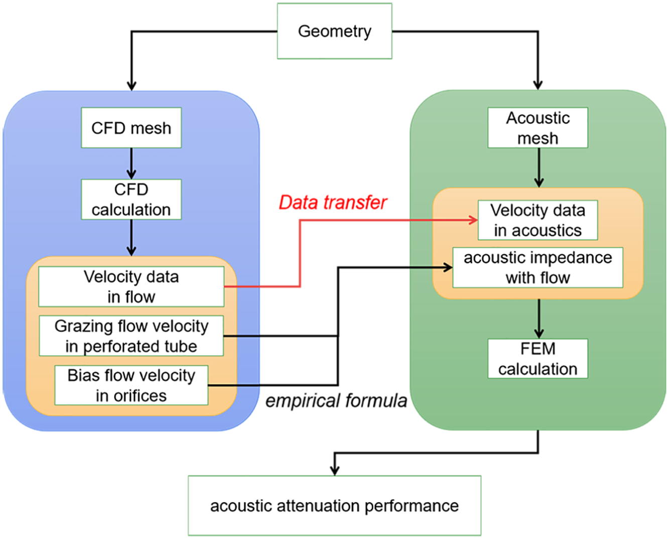
Process of one-way fluid-to-acoustic coupling between flow and acoustics.
FEM
It is assumed that the medium in the silencer is the inviscid irrotational gas. With the introduction of velocity potential


where ρ is perturbation of density, p is sound pressure, ρ0 is density of flow, c0 is sound speed, and
Once the sound pressure and perturbation of density are eliminated, the convected wave equation can be written as

The above equation can be solved numerically by the FEM. With the test function

where
Boundary conditions
In order to carry out finite element calculation, the appropriate boundary conditions need be discussed in the boundary integral of equation (5).
It is unnecessary to set the specific value of the velocity potential in inlet, because sound pressure we care about can be obtained by velocity potential and gradient of velocity potential in the equation (2). For simplicity, the inlet of silencer is set to unit normal mass flow

Assuming uniform flow in outlet tube of silencer, there are generally forward and backward moving plane waves in the axial direction. When non-reflecting boundary condition in the equation (7) is adopted, backward moving wave excludes

where
Combining the term of right side of equations (5) and (7) yields

On the rigid wall, boundary integral in the equation (5) equals to zero
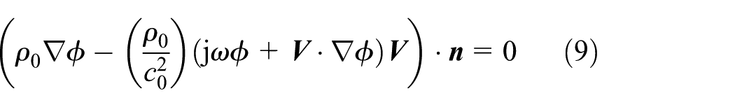
The Myers boundary condition 13 describes acoustic relationship between two sides of perforation

where zp is the acoustic impedance of perforation.
For the grazing flow, bias flow, and grazing-bias flow in the orifices of thin-walled tube, several previous empirical formulas of acoustics impedance are used in this study.
The acoustic impedance of perforates with grazing flow of Mach number MG can be found in Kang et al 7
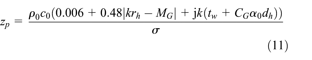
where k is the wave number, rh is the radius of orifices, dh is the diameter of orifices, tw is the tube thickness, σ is the perforated porosity, and

Equation (11) is an empirical formula obtained using CFD time-domain computations for the cases of MG ≤ 0.2, 2.5 mm ≤ dh ≤ 6 mm, 0.8 mm ≤ tw ≤ 2 mm, and σ < 26%. The sound pressure level was set to not exceed 120 dB to obtain the linear acoustic behavior.
The acoustic impedance of perforates with bias flow of Mach number MB can be found in Sullivan 8

where
Sun et al. 10 proposed an empirical formula of acoustic impedance with grazing-bias flow as below

where

Schematic of grazing-bias flow interaction model: (a) outflow and (b) inflow.
Data transfer
Figure 3 shows the CFD and acoustic mesh of straight tube, which have the diameter 50 mm and the length of 500 mm. Considering the non-matching between the two meshes, the flow velocity in the convected wave equation needs to be transferred from CFD results. In this study, zeroth-order interpolation (nearest neighbor) method of ANSYS Fluent is employed. The interpolation file is obtained by the function “mesh-to-mesh solution interpolation” in ANSYS Fluent and then imported into the acoustic mesh in COMSOL software. Figure 4 presents the radial velocity distribution in outlet before and after interpolation. It is found that the distribution is captured by the zeroth-order interpolation, and the result is reasonable for calculation of convection effect to sound propagation.

CFD and acoustic meshes of straight tube with a half of model.
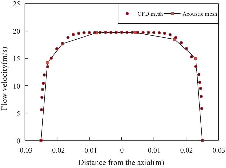
Radial velocity distribution in outlet before and after interpolation.
Acoustic attenuation performance of silencer
To evaluate acoustic attenuation performance of silencers, TL can be calculated by following equation in the frequency range below the plane wave cut-off frequencies of the inlet and outlet tubes

where S1 is cross-section area of the inlet, S2 is cross-section area of the outlet, pi is incident sound pressure on the inlet, and pt is transmitted sound pressure on the outlet.
The transmitted sound pressure in the outlet is calculated by equation (2) as the boundary condition of non-reflecting outlet is set. Assuming the uniform flow in inlet tube, the sound pressure and particle velocity may be expressed as


where x is axial direction of tube, p+ is sound pressure amplitude of forward moving wave, and p− is sound pressure amplitude of backward moving wave.
Using equations (15) and (16), we obtain

Thereby, the incident sound pressure on the inlet and the transmitted sound pressure on the outlet can be obtained using velocity potential and gradient of velocity potential.
Experimental validation
In this section, three types of silencers are selected to validate the one-way fluid-to-acoustic coupling approach by comparing the predictions and measurements.
Straight-through perforated tube silencer
Figure 5 shows the geometry of straight-through perforated tube silencer. The expansion chamber has the inner diameter D = 100 mm and the length l = 200 mm. The perforated tube has the inner diameter d = 32 mm, the tube thickness tw = 2 mm, the perforated diameter dh = 6 mm, and perforated porosity σ = 9%. The temperature of fluid is 288 K.

Straight-through perforated tube silencer.
To reduce the computation cost, this study uses the rotational periodic boundary condition. Figure 6 shows that the most of fluids pass through the perforated tube, and there is a small amount of fluids entering into the expansion chamber. Thereby, the flow field obtained from CFD computation is more reasonable than the conventional uniform flow assumption.
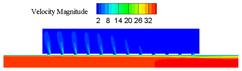
Velocity magnitude contour of straight-through perforated tube silencer (inlet velocity 34 m/s).
For the straight-through perforated tube silencers, bias flow velocity is much small than grazing flow velocity and so it is neglected. The empirical formulas of acoustic impedance in equation (11) is adopted for straight-through perforated tube silencers and the Mach number of grazing flow equals the ratio of inlet flow velocity to sound speed. Figure 7 compares the TL prediction and measurement 6 of the silencer, and good agreements between the numerical results and the previously published experimental measurements are observed in the frequency range of interest.

Transmission loss of straight-through perforated tube silencer (inlet velocity 34 m/s).
Flow-plug perforated tube silencer
Figure 8 shows the geometry of flow-plug perforated tube silencer. The expansion chamber has the inner diameter D = 101.6 mm and the length l1 = l2 = 128.6 mm. The perforated tube has the inner diameter d = 49.3 mm, the tube thickness tw = 0.81 mm, the perforated diameter dh = 2.49 mm, and porosity σ = 3.9%. The temperature of fluid is 347 K.
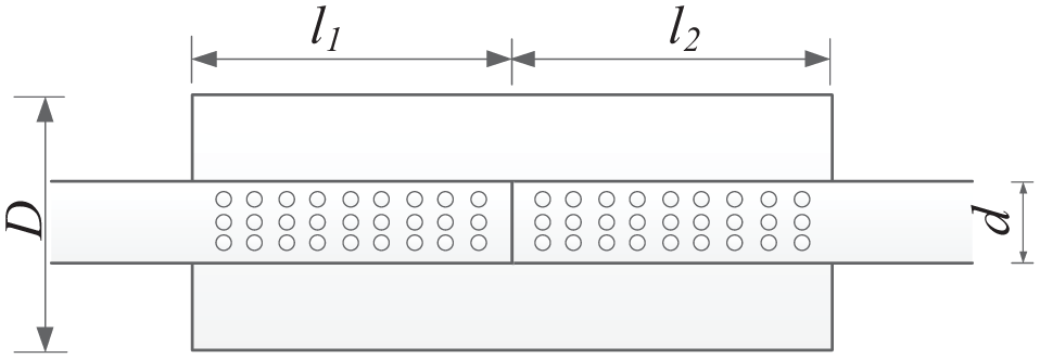
Flow-plug perforated tube silencer.
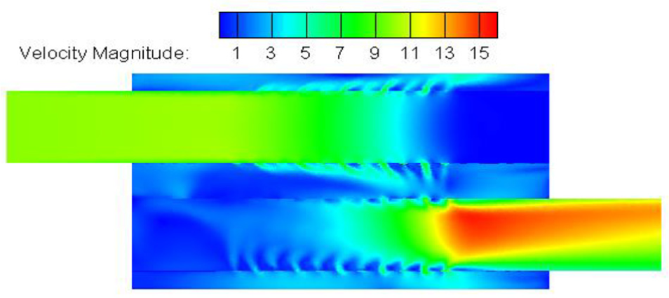
For the flow-plug perforated tube silencer, this study also employs the rotational periodic boundary condition. It can be found from Figure 9 that (1) the velocity distribution in the silencer is not uniform, (2) the regions with the higher velocities are located near orifices, and (3) the jet flow is formed in the expansion chamber and has different velocities at each orifices.

Velocity magnitude contour of flow-plug perforated tube silencer (inlet velocity 17 m/s).
For the flow-plug perforated tube silencer, the averaged MB in orifices equals 0.11 as inlet velocity of silencer is 17 m/s (MG = 0.046) and the ratio λ equals 2.4. The grazing flow is neglected and the empirical formulas of acoustic impedance in equation (12) is adopted for the flow-plug perforated tube silencer. Figure 10 shows that the numerical predictions coincide reasonably well with the published experimental measurement. 8 The discrepancy between numerical prediction and measurement may possibly be attributed to that (1) the formula of perforate acoustic impedance with bias flow has assumed to have the same flow velocity at each orifice; (2) flow generated noise exists as fluids pass the orifices in experiment; (3) there may be heat conduction between the fluid and the wall in the experimental measurement, which is not considered in the numerical simulation; and (4) sound transmission through the shell is not considered in the numerical prediction.

Transmission loss of flow-plug perforated tube silencer (inlet velocity 17 m/s).
Double perforated tube silencer
Figure 11 shows the geometry of double perforated tube silencer. The expansion chamber has the inner diameter D = 300 mm and the lengths L = 500 mm and l = 300 mm. The perforated tube has the inner diameter d = 100 mm, the tube thickness tw = 1 mm, the perforated diameter dh = 10 mm, and perforated porosity σ = 20%. The offset of inlet and outlet perforated tubes is c = 150 mm. The temperature of fluid is 288 K.

Double perforated tube silencer.
As shown in Figure 12, the velocity distribution inside the double perforated tube silencer is more complex than the previous silencers. Like flow-plug perforated tube silencer, the double perforated tube silencer also has two perforated tubes with bias flow. But the tubes are in a parallel arrangement. The averaged Mach number of bias flow MB in orifices equals 0.012 as inlet velocity of silencer is 10 m/s (MG = 0.03) and so the ratio λ equals 0.4. Figure 13 shows that the numerical prediction agrees well with the published experimental measurement. 14 However, more extensive verifications are necessary for perforated tubes with high porosity in future because the adopted equation (13) was derived from perforation with the low porosity σ < 4%.
Velocity magnitude contour of double perforated tube silencer (inlet velocity 10 m/s).

Transmission loss of double perforated tube silencer (inlet velocity 10 m/s).
Flow effect on the acoustic attenuation performance of silencers
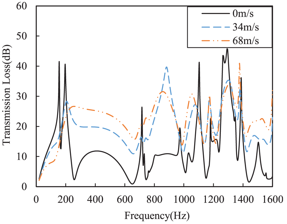
Figure 14 illustrated that the effects of flow on the TL of the straight-through perforated tube silencer is marginal in the plane wave range and obvious around the resonance and at higher frequencies. As flow velocity of inlet increases, the TL of the straight-through perforated tube silencer decreases at high frequencies somewhat. The effects of flow on the TL of flow-plug perforated tube silencer are more sensitive than the straight-through perforated tube silencer in Figure 15. Increasing the flow velocity of inlet, the TL of the silencer increases at most frequencies, which may be explained as the increase of the perforate acoustic resistance and decrease of the effective flow area of the orifices. As increasing the flow velocity in Figure 16, the acoustic attenuation performance of double perforated tube silencer at most frequencies is improved and the amplitude of resonance peaks lower somewhat.

Effect of flow on transmission loss of straight-through perforated tube silencers.

Effect of flow on transmission loss of flow-plug perforated tube silencers.

Effect of flow on transmission loss of double perforated tube silencer.
Next, we will focus on investigating the effects of flow on the acoustic attenuation performance of three-pass perforated silencer with various perforation configurations such as the number of perforated tubes and perforated bulkheads.
Figure 17 shows the baseline configuration of three-pass perforated tube silencer. The dimensions are as follows: δ1 = δ2 = 73 mm, l1 = 80 mm, l2 = 40 mm, l3 = 50 mm, l4 = 30 mm, la = lb = 40 mm, lc = 150 mm, ld = 107 mm, lp = 160 mm, D = 260 mm, and d = 100 mm for the major axis and minor axis of the elliptical cross section. The perforated tubes’ inner diameter is 48.8 mm, the tube thickness of tw = 1.5 mm, the perforated diameter of dh = 2.5 mm, and perforated porosity of σ = 6%.

Sketch of baseline configuration of three-pass perforated tube silencer.
It can be found from Figure 18 that the jet flow exists near the orifices. This phenomenon means that fluid flow into the middle chamber from the inside of the perforated tubes or into the perforated tubes from the middle chamber. Following the definition of Sun et al. 10 for grazing-bias flow type, inlet, center, and outlet perforated tubes belong to bias-inflow, bias-outflow and bias-inflow, respectively. According to bias flow averaged velocity in orifices and grazing flow velocity inside of perforated tubes, effective discharge coefficients of grazing-bias flow of baseline configuration can be calculated. Table 1 lists the effective discharge coefficients of various configurations of three-pass perforated tube silencer, which will be used in the next discussion.

Velocity magnitude contour of baseline configuration of three-pass perforated tube silencer (inlet velocity 34 m/s).
Effective discharge coefficients of grazing-bias flow of three-pass perforated silencers.

Comparing the acoustic attenuation performance of three-pass perforated tube silencer without flow, TL deceases seriously in the low frequency range as flow velocity increases, especially near the first resonant frequency, while TL increases at higher frequencies in general, as shown in Figure 19.
Effect of flow on transmission loss of baseline configuration of three-pass perforated tube silencer.
The four configurations of three-pass perforated silencer shown in Figure 20 are considered next. The inlet velocity of 34 m/s is chosen as default hereafter in this article to investigate the effects of flow on acoustic attenuation performance of the silencers.
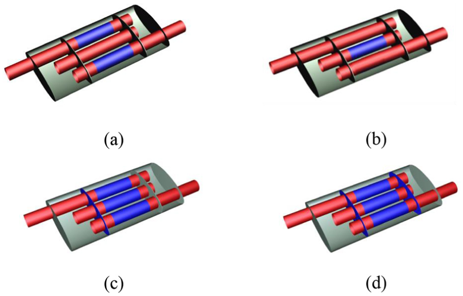
Configurations of three-pass perforated silencer: (a) solid center tube, (b) solid inlet/outlet tube, (c) perforated inlet bulkhead, and (d) perforated inlet and outlet bulkheads (blue region: perforated portion; red region: solid portion).
The effective discharge coefficients of various configurations are listed in Table 1 with the exception of configuration (b), for which only grazing flow exists in the center perforated tube. When bulkheads are perforated, the averaged bias flow velocity through the orifices of perforated bulkhead is 8 m/s for configuration (c), while the velocities are 3 m/s and 18 m/s through the orifices of inlet and outlet bulkheads for configuration (d), respectively.
The effects of flow on acoustic attenuation performance of silencers with various configurations are (1) the reduction of resonance peaks mainly and (2) increase of TL curves in general as shown in Figure 21. Similar to the baseline configuration silencer, TL of configuration (a) decreases seriously near the first resonant frequency, while TL increases at higher frequencies. Unlike grazing-bias flow exist in the baseline configuration, the effect of grazing flow in configuration (b) changes rarely high-frequency acoustic attenuation. The results of configurations (c) and (d) show that the flow increases acoustic attenuation performance at most frequencies. When the grazing-bias flow in the orifices of perforated tube and bias flow in the orifices of bulkheads exist simultaneously, the latter plays a leading role to the acoustic attenuation performance of configurations (c) and (d).

Effect of flow on transmission loss of three-pass perforated silencers: (a) solid center tube, (b) solid inlet/outlet tube, (c) perforated inlet bulkhead, and (d) perforated inlet and outlet bulkheads.
Conclusion
The one-way fluid-to-acoustic coupling approach is proposed to predict the acoustic attenuation performance of perforated silencers in the presence of flow. The comparisons between the numerical results of the present method and the previously published experimental measurements show the reasonably good agreements for three typical perforated tube silencers.
The effect of grazing flow is obvious on high-frequency acoustic attenuation of the straight-through perforated tube silencer, while marginal in the low frequency range. The bias flow enhances the acoustic attenuation of flow-plug and double perforated tube silencers at most frequencies. The grazing-bias flow reduces seriously acoustic attenuation near the first resonant frequency of three-pass perforated silencers and increases the TL in specific frequency range. When the grazing-bias flow in the orifices of perforated tube and bias flow in the orifices of bulkheads exist simultaneously, the latter plays a leading role to the acoustic attenuation performance of three-pass perforated silencers.
In the practical design of silences, the impact of the different kinds of the flow near orifices, for example, grazing flow, bias flow, and grazing-bias flow on the acoustic attenuation performance of perforated silencers should be considered carefully.
Footnotes
Handling Editor: Elsa de Sa Caetano
Declaration of conflicting interests
The author(s) declared no potential conflicts of interest with respect to the research, authorship, and/or publication of this article.
Funding
The author(s) disclosed receipt of the following financial support for the research, authorship, and/or publication of this article: The authors would like to acknowledge the support of research grant 11674076 from the National Natural Science Foundation of China and Marine Low-Speed Engine Project - Phase I.