
Abstract
In this study, to investigate the friction and wear behaviours of cutting tools made of YG8-cemented carbide in the process of cutting austempered ductile iron, friction and wear tests at different applied loads (100–500 N) and sliding speeds (40–120 m/min) under conditions of dry, chilled air and minimal quantity lubrication were carried out using a tribometer and a composite spray cooling device. In addition, the morphology and material transmission of the worn surfaces were analysed by scanning electron microscopy and energy dispersive spectroscopy. The results showed that the wear rates of the YG8 pins increased with increasing applied loads; however, the sliding speed exerted no significant influence on wear of the YG8 pins. Under dry conditions, the worn surface was mainly found to exhibit abrasive wear under a low load. With increasing loads, the transfer films were formed, and then led to fracturing and spalling of the frictional surfaces. Under chilled air and minimal quantity lubrication conditions, the worn surface was smoother than that under dry conditions. The most favourable results were obtained under minimal quantity lubrication condition due to the oil film formed on the surface of the frictional pairs.
Keywords
Introduction
Austempered ductile iron (ADI) has been used in various fields such as construction, engineering, metallurgical machining and automobile engineering due to its distinct advantages including high strength and ductility, high wear resistance and low production cost;1–4 however, because of ADI exhibiting characteristics including a high coefficient of strain hardening and a low thermal conductivity, there are high cutting forces and temperatures in machining ADI, and then the service life of cutting tools is reduced. Thus, ADI can be considered as a typical difficult-to-machine material. 5 Cemented carbide is one of the most common materials used for preparing cutting tools to cut cast iron. Many researchers6–9 have carried out research into the cutting of ADI with cemented carbide cutting tools. Cakir and Isik 6 studied the effects of austempering temperature and time onto the machinability of ADI. Six pairs of specimens were austempered at 300°C, 350°C and 400°C for 1 and 2 h. The results showed that the hardness of ADI decreases with increasing austempering temperature and increases with austempering time. And the high strength and hardness of ADI have caused many researchers and engineers to doubt the machinability of this material. Compared with ordinary ductile iron, the highest increase in the tangential cutting force (i.e. 23%) was in group B (DI austempered at 400°C for 2 h).
Quasi-dry cutting technology, such as chilled air, minimal quantity lubrication (MQL) and oil-on-water cooling, has low environmental pollution and high resource utilisation during cutting, while also reducing the temperature in the cutting zone, improving surface quality and reducing tool wear. Under chilled air conditions, the chilled air erodes the cutting zone by a jet flow. Many researchers10–12 have showed that cutting under chilled air conditions has various merits including decreasing cutting temperatures, extending the life of cutting tools and improving quality of the machined surface. Mohd Rodzi et al. 12 carried out an experimental investigation in turning cast iron by carbide-coated cutting insert under chilled air conditions. The results revealed that the service life of cutting tools under chilled air improved by about 30% compared with ordinary air conditions. Under MQL conditions, the compressed air and a small amount of cutting oil were mixed and evaporated, and then the millimetre- and micron-sized fogs were produced to spray the cutting zone. By doing so, the contact interfaces between the cutting tools and chips, as well as between cutting tools and workpieces, were cooled and lubricated. Based on the permeation mechanism of MQL, 13 it can be seen that minimal oil-mist particles easily permeate into the cutting zone to achieve lubricating effect. Many researchers8,14,15 have investigated cutting under MQL conditions and indicated that it improves the behaviour of cutting tool–workpiece friction pairs and further reduces the tool wear. Meena and Mansori 8 conducted tests on drilling ADI using TiAlN-cemented carbide cutting tools under dry and MQL conditions. The results indicated that smaller cutting force and better surface quality resulted from the use of MQL conditions than under dry conditions at the same cutting parameters. The tool life in case of dry drilling was 80 holes and in case of MQL drilling 110 holes.
In the cutting process, there is significant frictional contact between cutting tools and workpieces, in which the tribological behaviour exerts an important effect on the machined surface quality and service life of the cutting tools. The aforementioned scholars carried out friction and wear behaviour of cutting tools in machining under different cutting conditions. There are several factors affecting the friction and wear behaviours in cutting process, such as the material properties of the cutting tools and workpieces, the stress distribution, temperature distribution, sliding speed, the physico-chemical reactions under different cutting conditions and cutting parameters. Compared with the cutting process, the friction and wear tests are quick and simple, show a wider range of parameters, are easy to control and can comprehensively investigate the wear of cutting tool materials. To investigate the cutting tool material made of YG8-cemented carbide, friction and wear tests under dry, chilled air and MQL conditions using a pin-on-disc tribometer and composite spray cooling device were carried out. By doing so, the friction process was analysed to allow further investigation of the friction and wear behaviour of the friction pairs composed of the cutting tool material of YG8 sliding against workpiece material of ADI.
Experimental work
Experimental materials
The pin samples, measuring Φ4 × 15 mm, were made of commercial YG8-cemented carbide (equivalent to K20, ISO standard). YG8 is a tungsten-cobalt-type alloy material with Co content of about 8%, density of 14.7 g/cm3, hardness of HRA89 and tensile strength of 1500 MPa. The disc samples of ADI have a diameter of 43 mm and a thickness of 3 mm. The ADI materials were provided by Shijiazhuang Fuerkai Casting Development Co., Ltd and it carried out austempering treatment of QT500-7 ductile iron; the parameters of the heat treatment process included the following: austenitising temperature of 900°C, a holding time of 90 min, an isothermal quenching temperature of 300°C and a holding time of 60 min. The densities and mechanical properties of ADI are listed in Table 1.
Densities and mechanical properties of ADI.

Experimental method
Using an MMU-10G tribometer (Figure 1), the friction and wear behaviours of the YG8–ADI friction pairs were investigated. The tribometer with a load range of 60–10 kN, a maximum sliding speed of 175 m/min and a maximum friction torque of 15 Nm was used. The OoW129 composite spray cooling system (Figure 2) was used for preparing chilled air and MQL. It produced chilled air or oil mist, which was blown onto the friction zone through a nozzle at a high pressure. The oil consumption can be adjusted according to the material properties and machining requirements. Figure 3 shows the pin-on-disc sliding tests under chilled air and MQL conditions, where A, B, C and D refer to the disc sample, the fixture of the pin sample, the pin sample itself and the nozzle, respectively. The disc sample A was not rotated, and the load was applied from the bottom to up by a hydraulic system. The fixture B was rotated by the principal motor, while the pin sample C was subjected to rotary motion over a radius of 11 mm. The nozzle D was used to jet the chilled air or oil–gas mixture into the friction zone at high pressure.
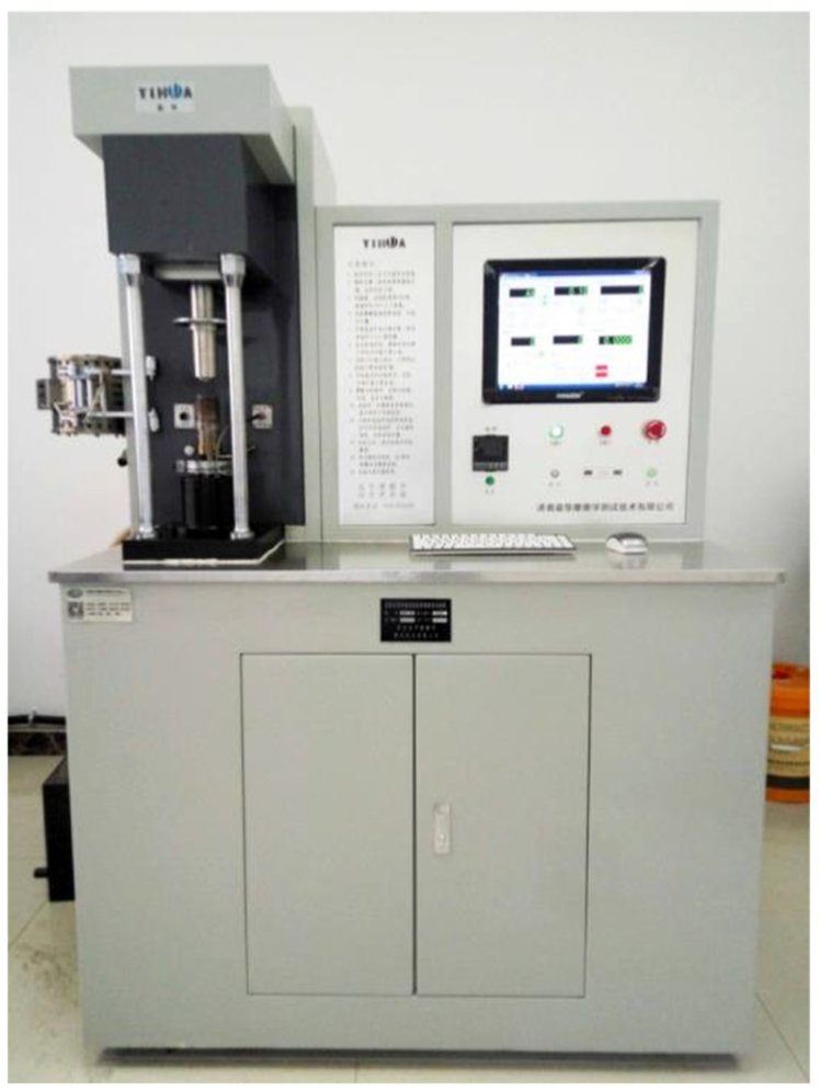
MMU-10G tribometer.

Composite spray cooling system.
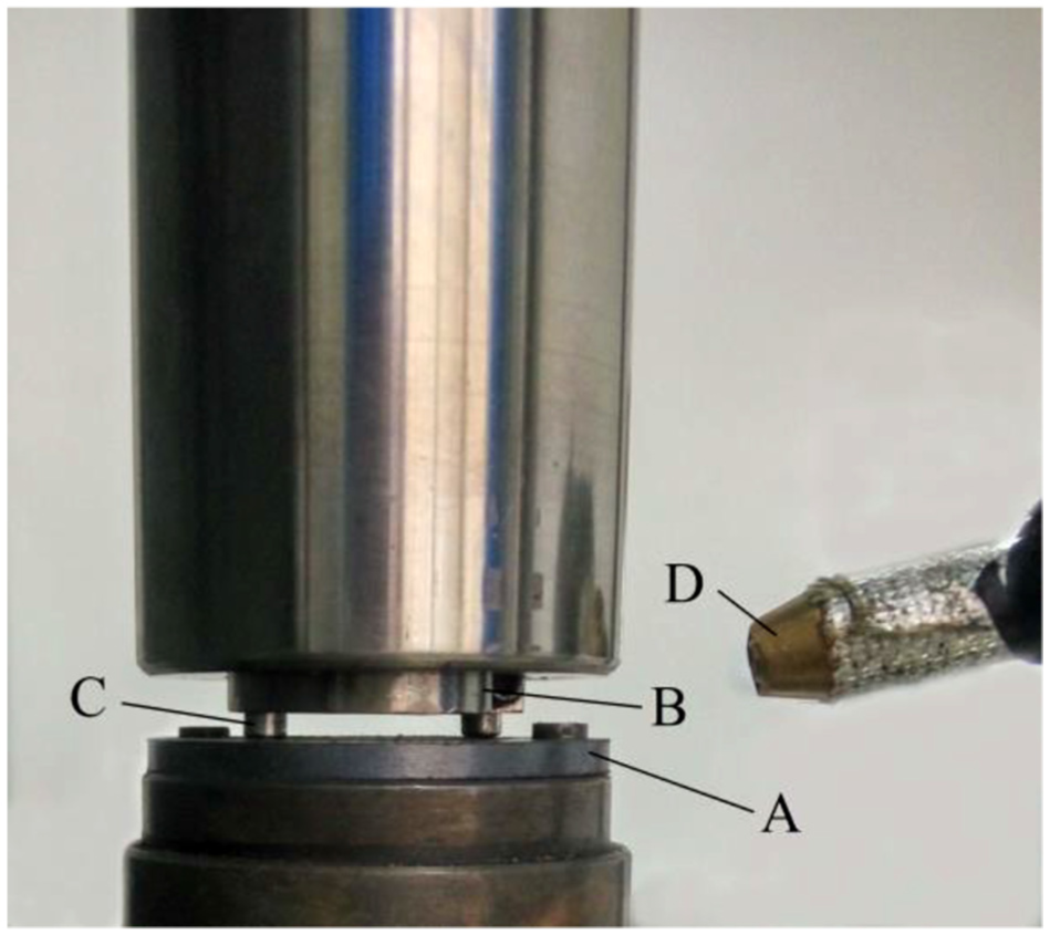
Pin-on-disc sliding tests under chilled air and MQL conditions.
After being ground by 1500# metallographic sandpaper, the surfaces of samples were used for the friction and wear tests under dry, chilled air and MQL conditions. The parameters under chilled air conditions were set as follows: the air pressure was 0.8 MPa, the chilled air temperature was −30°C and the air consumption was 350 L/h. The parameters under MQL conditions were set as follows: the air pressure was 0.8 MPa, the oil (Microlube 2000) feed rate was 15 mL/h and the air consumption was 350 L/h. The applied loads were equal to 100, 200, 300, 400 and 500 N, while the normal sliding speeds were 80 m/min under dry, chilled air and MQL conditions to study the effects of applied loads on friction and wear behaviours. The sliding speeds applied were equal to 40, 60, 80, 100 and 120 m/min, while the normal applied loads were 300 N under dry, chilled air and MQL conditions to study the effects of sliding speeds on friction and wear behaviours. The total distance for each sliding friction test was 2000 m. Each set of tests was carried out at least three times. The mean average coefficients of friction and its changes over time were obtained using the aforementioned tribometer. Before and after testing, the pins and discs were subjected to ultrasonic cleaning for 2 min and then weighed on a BSA224 S-CW electronic scale (resolution = 0.1 mg). The volumetric wear rate can be calculated using formula (1)

where
Results and discussion
Friction coefficient and wear rate
Figure 4 shows the changes in friction coefficient (the average friction coefficient in the stable friction stage) of YG8–ADI friction pairs under dry, chilled air and MQL conditions.

Friction coefficients of YG8–ADI friction pairs with (a) applied loads and (b) sliding speeds under dry, chilled air and MQL conditions.
It can be seen from Figure 4(a) that the variations of the friction coefficients with the applied loads under dry, chilled air and MQL conditions were basically the same, which meant that the friction coefficients all decreased with the increasing loads. Before reaching 300 N, there was some difference in the friction coefficients under the three experimental conditions at the same load: the friction coefficients under dry conditions were slightly larger than those in the other two conditions, followed by that under chilled air, and the friction coefficients under MQL conditions were relatively lower. However, at beyond 300 N, the friction coefficients were similar at the same load under the three experimental conditions. In the process of experiment, the graphite in ADI separated out on the surface under the action of frictional heat and stress. Graphite has self-lubricating properties, and it can lubricate sliding surfaces. Therefore, the YG8–ADI friction pairs presented lower friction coefficients and wear rates than other metals, especially under dry conditions. Under MQL conditions, lubrication performance on the contact interfaces is only a little better due to slightly lower friction coefficients. It can be seen from Figure 4(b) that the friction coefficients of the YG8–ADI friction pairs did not change significantly with increasing sliding speeds under the three experimental conditions. Under MQL conditions, the friction coefficient stabilised when the sliding speed was below 80 m/min, while it decreased at sliding speed above 80 m/min. Overall, the applied load had a significant influence on the friction coefficient, while the sliding speed did not significantly affect the friction coefficient.
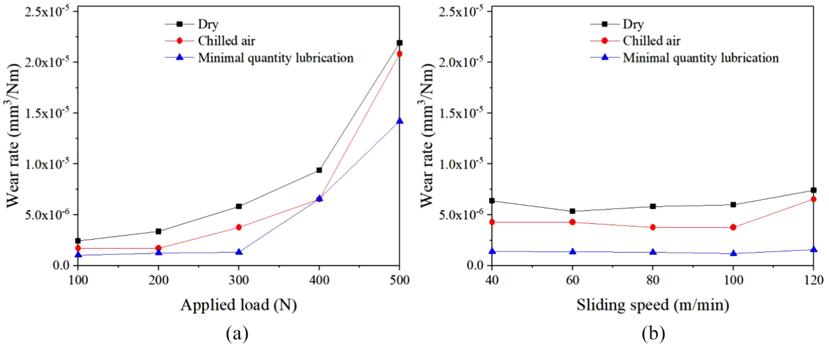
Figure 5 shows the variation in the wear rates of YG8 pins under dry, chilled air and MQL conditions. It can be seen from Figure 5(a) that the wear rates did not vary significantly when the loads were lower than 200 N, while they increased at the applied loads greater than 200 N under all conditions. As the loads increased beyond 400 N, the increased wear rates decreased. At the same applied load, the maximum wear rate occurred under dry conditions, followed by that under chilled air and MQL conditions. As shown in Figure 5(b), the wear rates increased with increasing sliding speeds in the range of 40–60 m/min; but when the sliding speeds were between 60 and 80 m/min, the wear rates stabilised and then rapidly increased when the sliding speeds exceeded 80 m/min. In dry and chilled air conditions, the wear rates of YG8 pins varied little and were both significantly larger than that under MQL conditions. It is due to the cooling and lubricating effects of MQL.

Wear rate of YG8 pins with (a) applied loads and (b) sliding speeds under dry, chilled air and MQL conditions.
Figure 6 shows the variation in the wear rates of ADI discs under dry, chilled air and MQL conditions. As shown in Figure 6(a), the wear rates were increasing with increasing applied loads under dry and chilled air conditions, and the wear rates increased rapidly when the applied loads exceeded 400 N. But under MQL conditions, the wear rates were basically unchanged when the applied loads were below 300 N and then they rapidly increased after the applied loads exceeded 300 N. At the same applied load, the maximum wear rate occurred under dry conditions, followed by that under chilled air and MQL conditions. It can be seen from Figure 6(b) that the wear rates of the ADI discs were stable at sliding speeds of less than 100 m/min and it rose thereafter under dry and chilled air conditions. But under MQL conditions, the wear rates of the ADI discs remained significantly lower than those under the other two conditions.
Wear rate of the ADI discs with (a) applied loads and (b) sliding speeds under dry, chilled air and MQL conditions.
Friction and wear mechanism
Figure 7 shows the SEM/EDS of worn surfaces of YG8 pins under different applied loads under dry conditions. At a load of 100 N (Figure 7(a)), the worn surface was relatively smooth except for some tiny wear debris and slight scratching, and no significant damage. As the applied load increased to 200 N (Figure 7(b)), a small amount of wear debris and insignificant amounts of transferred substances were seen on the worn surface and the wear morphologies mainly appeared as micro-ploughed furrows. This indicated that the wear mechanism was abrasive wear. It can be seen from EDS analysis (Figure 7(g)) of G zones in Figure 7(b), that there were significant amounts of elemental Fe and O present. The presence of elemental O revealed that the worn surface had been subjected to a chemical reaction caused by friction to result in the formation of oxides (mainly of Fe). The presence of Fe implied that the transmission of disc materials probably occurred in the friction process or that the Fe was generated from wear debris. When the loads reached to 300 N (Figure 7(c)) and 400 N (Figure 7(d)), discontinuous transfer films were found on the worn surfaces of the YG8 pins. At 400 N, these transfer films covered almost all the worn surface. The EDS analysis (Figure 7(h)) of H zones in Figure 7(d) showed that these transfer films were oxide films, which was caused by most transferred substances and wear debris being compacted under the large applied load to lead to a friction-induced chemical reaction. Although part of these oxide films was discontinuous, it can be seen from Figure 4(a) that the friction coefficients decreased with increasing loads and therefore the presence of these oxide films caused the reduction in the friction coefficient. When the load rose to 500 N (Figure 7(e)), the oxide films on the frictional surface were severely damaged under the effect of subsequent friction shear and large load due to their large thickness. As a result, large area of brittle fracture and spalling appeared in which some cemented carbide materials were removed. By analysing the magnified SEM image (Figure 7(f)) of Figure 7(e), there were seen to be significant micro-cracks formed on the surface of the oxide films. This indicated that the major wear mechanism was found to be brittle fracture and spalling at 500 N.
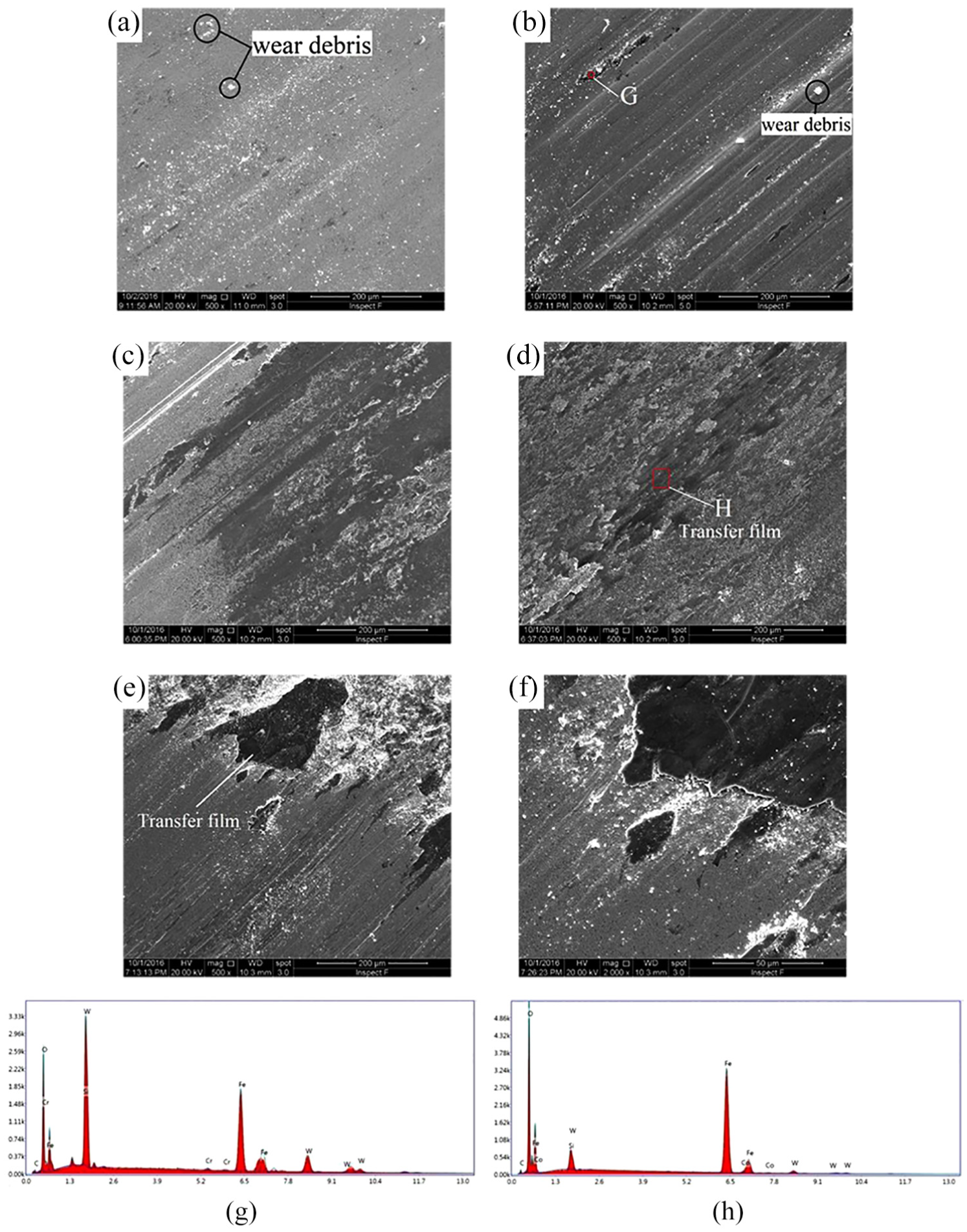
SEM images of worn surfaces of YG8 pins at the applied loads of (a) 100 N, (b) 200 N, (c) 300 N, (d) 400, (e, f) 500 N and (g) EDS in G and (h) H zones under dry conditions.
Figure 8 shows the SEM images of worn surface and EDS of ADI discs with the loads of 400 and 500 N under dry conditions. Under the load of 400 N (Figure 8(a)), the ADI disc exhibited various characteristics including pits, brittle fracture zones and micro-cracks. At a load of 500 N (Figure 8(b)), a large area of materials was spalled off the worn surface of the ADI disc which was subjected to significant spalling. It can be seen from EDS analysis (Figure 8(c) and (d)), that the content of W element on the worn surface is increased significantly at the applied loads of 400 and 500 N, respectively. This implied that the coupled YG8 pins were subjected to significant material transmission, which aggravated the wear of the YG8 pins’ surface at the applied loads of 400 and 500 N.

SEM images of worn surfaces of ADI discs at the applied loads of (a) 400 N and (b) 500 N and (c) EDS in C and (d) D zones under dry conditions.
Figure 9 shows the SEM images of worn surfaces of the YG8 pins at different sliding speeds under dry conditions. When the sliding speed was 40 m/min (Figure 9(a)), many debris particles were found on the worn surface, which showed slight scratching. At a sliding speed of 60 m/min (Figure 9(b)), discontinuous transfer films appeared on the worn surface of the YG8 pin. With increasing sliding speeds, although discontinuous spalling appeared in local zones, relatively smooth films were formed (Figure 9(c)). When the sliding speed was 120 m/min (Figure 9(d)), the significant amount of the worn surface of the YG8 pin was covered by transfer films. The EDS analysis revealed that the amount of O element in the transfer films decreased (Figure 9(e)). The components in the transfer films were similar to those of ADI, which indicated that ADI material appeared as pieces which were bonded and transferred to the YG8 pin surface.
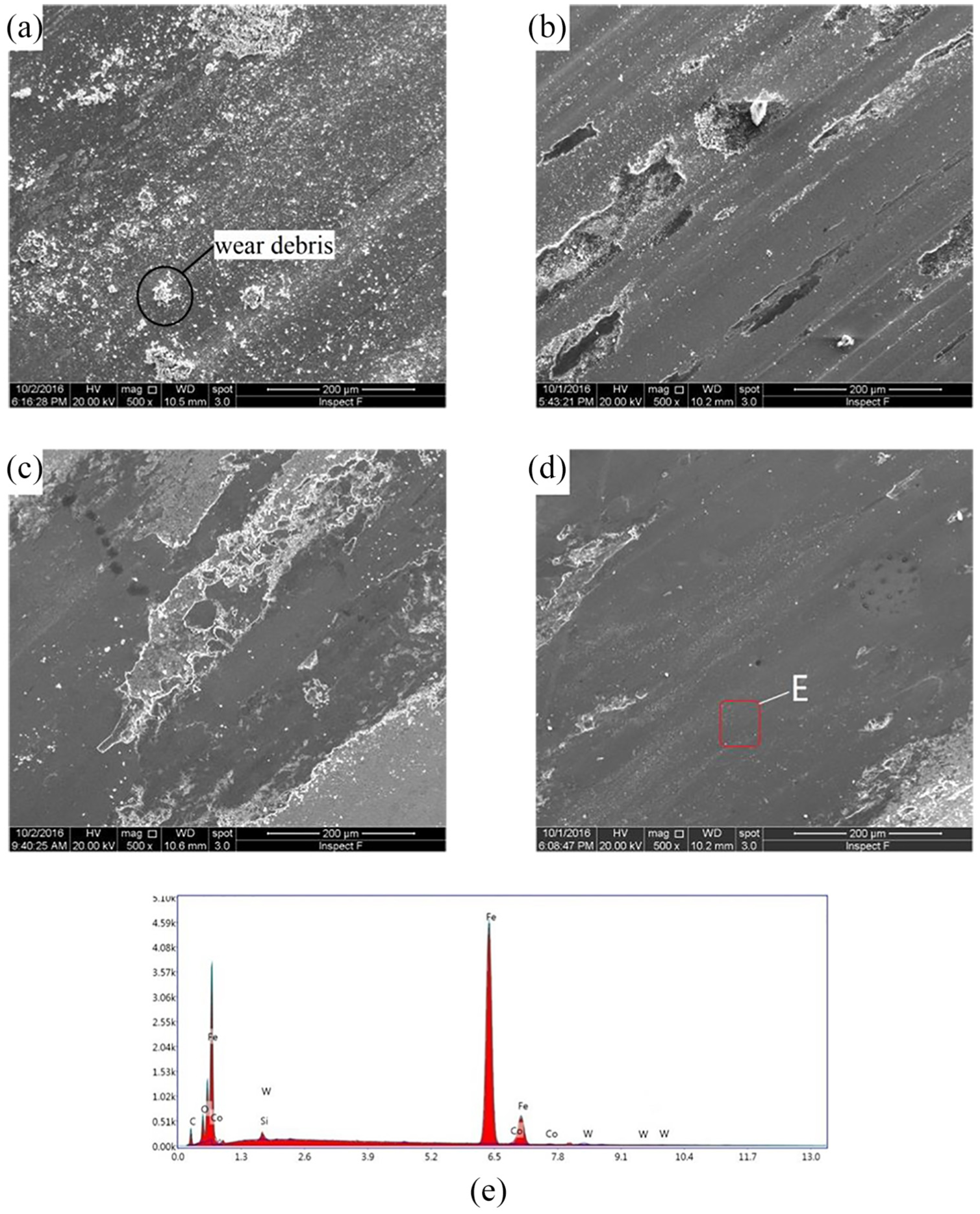
SEM images of the worn surface of the YG8 pins at the sliding speeds of (a) 40 m/min, (b) 60 m/min, (c) 100 m/min and (d) 120 m/min and (e) the EDS of E zone under dry conditions.
Figure 10 shows the SEM images of the worn surface of ADI discs and the EDS analysis at sliding speeds of 100 and 120 m/min under dry conditions. When the sliding speed was 100 m/min (Figure 10(a)), the worn surface mainly showed signs of local spalling. When the sliding speed was increased to 120 m/min (Figure 10(b)), the worn surface of the ADI disc became smooth although local spalling also occurred compared with that at the sliding speed of 100 m/min. Based on the EDS analysis (Figure 10(c) and (d)) of the ADI discs, the content of W element on the worn surface increased significantly upon onset of significant material transmission, which aggravated the surface wear of the YG8 pin at the given sliding speed.

SEM images of the worn surface of the ADI discs at the sliding speed of (a) 100 m/min and (b) 120 m/min and the EDS analysis of (c) C and (d) D zones under dry conditions.
Figures 11 and 12 show the SEM images of the worn surfaces of the YG8 pins under different applied loads at the sliding speed of 80 m/min under chilled air and MQL conditions. At a load of 100 N (Figures 11(a) and 12(a)), the wear debris were less than those under dry conditions (Figure 7(a)) because some of the wear debris were blown away by compressed air. At a load of 200 N, the worn surface (Figure 11(b)) of the YG8 pin under chilled air conditions mainly exhibited micro-ploughed furrows and slight scratching, showing the transfer of some coupled materials; however, the worn surface (Figure 12(b)) of the YG8 pin under MQL conditions was relatively smooth, with some small transfer films. Similar to dry conditions, there were significant amounts of elemental Fe and O present in transfer films (Figures 11(f) and 12(f)). And the presence of these oxide films also caused the reduction in the friction coefficient. The scratches and ploughed furrows on the worn surfaces of the YG8 pins under chilled air and MQL conditions were not obvious, showing smoother surfaces, compared with that (Figure 7(b)) under dry condition at the same parameters. This was due to the wear mechanisms of the YG8 pin worn surfaces under medium–low load mainly appeared as scratching and abrasive wear; however, under chilled air and MQL conditions, some of the wear debris was blown away by compressed air, therefore it was unlikely that wear debris were being pressed onto the surface of the YG8 pins. Furthermore, the surface of the YG8 pins became smoother, thus further reducing the abrasive wear thereof, and the worn surface was smoother under the effect of lubricating oil under MQL conditions. As the loads increases, the transfer films did not increase rapidly like those under dry condition, which may be due to the temperature at the friction zone under chilled air and MQL conditions far lower than that under dry condition of the cooling and lubricating capacities. At a load of 500 N, under chilled air conditions (Figure 11(e)), the temperature of the friction zone was decreased due to the cooling effect of the chilled air which further decreased the friction coefficient and wear rate. The worn surface of the YG8 pin had a fewer transfer films with insignificant oxidative wear compared with that under dry condition at the same parameters (Figure 7(e)). Under MQL conditions (Figure 12(e)), a layer of oil lubricating film is formed on the surface of the friction pairs,16,17 and the two surfaces of the friction pairs are, respectively, in contact with the oil lubricating film, which reduces the direct contact area and the adhesion point between the frictional interfaces. This meant that the resistance encountered by the friction pairs becomes the viscosity of the oil lubricating film rather than the shear strength of the materials. Therefore, the friction coefficients and the wear rate of the friction pairs decreased. Hence, the cooling and lubricating capacities are important factors determining the extent of the friction and wear under dry, chilled air and MQL conditions. With increasing cooling and lubricating capacities, both the friction coefficients and the wear rates gradually decreased.

SEM images of worn surfaces of the YG8 pins at the applied loads of (a) 100 N, (b) 200 N, (c) 300 N, (d) 400 and (e) 500 N and (f) EDS in F zone under chilled air conditions.

SEM images of worn surfaces of the YG8 pins at the applied loads of (a) 100 N, (b) 200 N, (c) 300 N, (d) 400 and (e) 500 N and (f) EDS in F under MQL conditions.
Conclusion
The friction coefficients of the YG8–ADI friction pairs decreased with increasing applied loads and sliding speeds in which the sliding speed did not significantly affect the friction coefficient under dry, chilled air and MQL conditions. Overall, the maximum friction coefficient was found to have acted under dry conditions, followed by that under chilled air conditions, and then under MQL conditions.
The wear rates of the YG8 pins and the ADI discs non-significantly increased with increasing applied loads under dry, chilled air and MQL conditions. Overall, the wear rate was maximised under dry conditions, followed by that under chilled air conditions, and then under MQL conditions.
Under dry conditions, the wear mechanism at a load of 100 N mainly appeared as scratching, while abrasive wear occurred at 200 N. With increasing loads, transfer films were formed, which then led to fracturing and spalling of material.
Under chilled air and MQL conditions, wear debris were blown away by the compressed air stream and therefore, the worn surface was smoother than that formed under dry conditions. The most favourable results were obtained under MQL conditions due to the oil film formed on the surface of the friction pairs.
Footnotes
Handling Editor: Crinela Pislaru
Declaration of conflicting interests
The author(s) declared no potential conflicts of interest with respect to the research, authorship and/or publication of this article.
Funding
The author(s) disclosed receipt of the following financial support for the research, authorship and/or publication of this article: This project was supported by the Science and Technology Plan Project of Gansu Province (grant no. 18JR3RA226), Innovation Team of Gansu Province (university grant nos 2016 C-7 and 2018 C-23) and the National Natural Science Foundation of China (grant no. 51865027).