
Abstract
The challenges such as large frictional drag, difficult weight-on-bit transmission, and low rate of penetration are frequently met in modern directional drilling, especially in horizontal well drilling. This study presented a nonlinear dynamic simulation model of horizontal well considering the random interaction between drill string and wellbore as well as bit and rock. In this study, the dynamic characteristics of the bottom hole assembly during drilling with and without agitator as well as the working mechanism and optimization parameters of the agitator were simulated and compared. The field application of the agitator is also simulated for the design and working parameter optimization. The results show that using agitator can improve the weight-on-bit transmission efficiency and reduce the frictional drag, tropsh-pressure, and occurrence probability of drill string buckling. The optimal installation position of the ∅172 mm agitator obtained in this study is [200, 300] m away from the bit, the optimum frequency range is [3, 17] Hz, and the optimal impact load is 100 kN.
Introduction
Directional drilling has been widely used in oil and gas drilling throughout the world such as horizontal wells, highly deviated wells, and extended reach wells. However, there are many problems met in directional drilling, especially in horizontal well, such as large frictional drag, difficult weight-on-bit (WOB) transmission, and low rate of penetration (ROP). The directional wells’ trajectories become more and more irregular and deep; the drilling of horizontal well, extended reach well, and highly deviated well will face even greater challenges. If the trajectory in the horizontal section is long enough, then the dead weight of the drilling tools and frictional drag will become excessively large; as a result, the WOB cannot be effectively transferred to the bit due to the large frictional drag caused by the contact between drill string and borehole wall. Buckling will also occur in the drill string under the action of WOB and frictional drag.
The drill string buckling may be changed from sinusoidal buckling mode to helical buckling mode under extreme conditions. Once buckling changes to the helical buckling mode, the drill string will be deadlocked immediately by the normal contact force, as well as the tangent friction force between the drill string and borehole. Reducing the friction force, increasing the WOB transfer efficiency, and raising the ROP are the main problems faced in extended reach and horizontal well drilling engineering. From the perspective of anti-friction technology, many investigations have been made to solve this problem.1–6 Various tools such as agitator have been developed and designed to resolve contradictions and improve the extended limits of horizontal wells.7–9 Engineering applications have shown that a small number of anti-frictional tools, such as agitator, had a certain effect on drilling engineering.10–12 The agitator is a derivative production of the screw motor, which can generate axial vibration with certain frequency and amplitude. Due to the axial excitation applied on the bottom hole assembly (BHA), the traditional static contact behavior between the drill string and wellbore is changed into the dynamic. 13 The friction force between the drill string and wellbore will be reduced and the efficiency of the WOB transmission will be improved. Based on the dynamic friction model and microscopic contact deformation theory, a theoretical model is proposed to explain the friction reduction caused by the agitator. 14 The dynamic response of the drill string due to the axial excitation proved by the agitator is examined via a forced-frequency approach. The analysis results illustrated that the effectiveness of the agitator is related to the operational parameters and structural characteristics of the drill string. 15 The transfer matrix approach is used to reflect the effect of the excitation source on the drilling performance. 16 However, the intended effect cannot be obtained due to lack of understanding of the working mechanism and parameter optimization of the agitator. The theoretical analysis of the working mechanism and optimization parameters of the agitator involves not only the contact and impact between the drilling string and borehole wall, but also the random interaction between the bit and rock. It is a nonlinear problem and its computation is quite difficult.
This study established a nonlinear dynamic finite element model (FEM) for BHA, where the contact and impact between the drilling string and borehole wall, and the random interaction between the bit and rock are considered. The dynamic characteristics of the BHA during drilling with and without agitator, as well as the working mechanism, optimal installation location, and working parameters of the agitator, are investigated through a series of numerical simulations. The field application of the agitator is also carried out based on the simulation results for the agitator design and working parameter optimization.
The numerical model
A nonlinear dynamic model of the BHA is established based on the energy equation. Four basic assumptions were made to reduce the computation: (1) the drill string axis coincides with the axis of the borehole under the initial conditions; (2) the influence of the drilling pipe tool joint on the movement of the drilling string is ignored; (3) the bit is much higher than the strength and hardness of the rock, and the bit is assumed to be rigid; and (4) an element is removed from the mesh if rock failure occurs, ignoring the influence of the failure units on subsequent drilling. This study models the BHA with an agitator in a horizontal well primarily with the following three problems: the constitutive model of the rock, the mathematical model of the bit–rock contact, and the dynamic response model of the BHA in the horizontal well.
The agitator
The agitator setup consists of two main parts: the positive displacement motor (PDM) section and valve plates. The rotor of PDM causes the plate to oscillate when the drilling fluid flows through the agitator, and this plate moves above a static plate with a hole. The oscillating plate changes the flow area and creates pressure pulses causing the vibration of drilling tools and the static friction state is broken. 17 The axial impact force at time t1 is the maximum due to the minimum overlap of the two valve plates. At time t2, the force is the minimum because of the two valve plates completely overlapped, as shown in Figure 1.
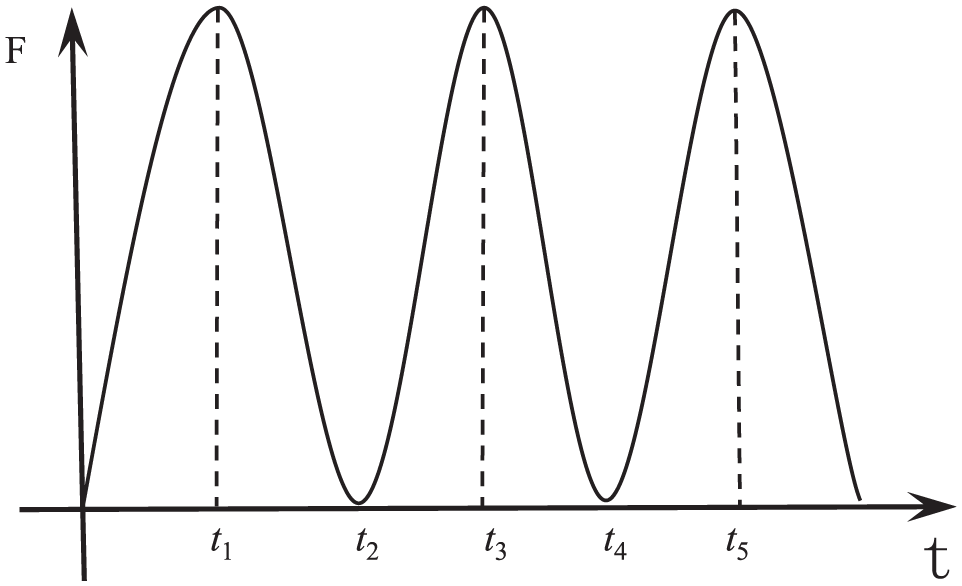
Axial impact force of the agitator.
The mathematical model of the bit–rock contact
Extreme nonlinearity appears during the drilling process, such as the contact nonlinearity between the bit and rock. The mathematical model of the bit–rock contact is established based on the D’Alembert principle and FEM theory 18
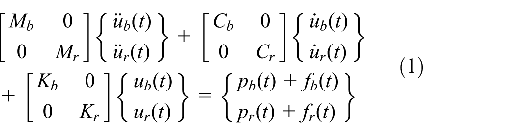
where Mb means the mass matrix of the bit; Mr represents the mass matrix of the rock; Cb represents the damping matrix of the bit;
The rock’s constitutive model
The constitutive model for the rock includes the elastic model and the plasticity model. The rock is considered to be homogeneous and isotropic in this study. During the elastic stage, the expression of stress can be established 19 as

The strength criterion of the rock in the FEM used in this study is the Drucker–Prager criterion developed based on the Mohr–Coulomb criterion and Mises criterion 20

where I1 means the first invariant of the stress tensor; J2 represents the second invariant of the stress deviator;
During the drilling process, the rock elements will fail provided that their plastic strain reaches a certain value. The rock damage criterion is introduced as follows 21

where
The dynamic model of BHA in the horizontal well
The dynamic model of the BHA in the horizontal well is established based on the Hamilton principle and FEM theory, and the finite element (FE) equation of dynamics is as follows 22

where
Previous studies defined the bit as one node, and the interaction between the bit and rock was simplified as axial displacement excitation in which the amplitude is sinusoidal.23–25 However, the vibration of the bit consists of not only longitudinal and lateral vibration, but also stick-slip vibration.26,27 The properties of the rock have an effect on the dynamic characteristics of the bit. Therefore, the simplified method described above does not precisely interpret the dynamic characteristics of the bit. The bit is the excitation source of the drilling string system vibration, which will also affect the dynamic characteristics of the bit. The excitation defined as a single direction from the bit to the drilling string system is inaccurate. In order to accurately describe the dynamic characteristics of the bit and drill string, this dynamic simulation model of the BHA takes the bit–rock and drilling string–wellbore wall interaction in real time as the boundary condition.
The computational method
Explicit dynamic analysis is an effective tool to solve nonlinear problems, and the explicit dynamic method is much more effective than the implicit method for expressing the contact condition. 28 Therefore, the dynamic method is used to analyze the FEM in this article because of the extreme nonlinearity appearing during the drilling process, such as contact nonlinearity of the bit–rock and drilling string–wellbore wall interaction, and material nonlinearity of the rock.
The explicit dynamic analysis procedure is based on the implementation of the explicit integration rule together with the use of diagonal or “lumped” element mass matrices. The motion equations of the body are integrated using the explicit central difference integration rule

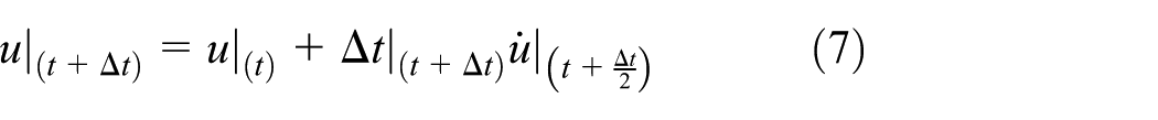
where
The key to the computational efficiency of the explicit procedure is to use diagonal element mass matrices, because the inversion of the mass matrix used in the computation for acceleration at the beginning of the increment is triaxial, and the acceleration at time t can be expressed as

where M is the mass matrix, P is the applied load vector, and I is the internal force vector.
Simulation results and discussion
The three-dimensional models of the borehole wall, drilling string, polycrystalline diamond compact (PDC) bit, and rock are created with the computer-aided design (CAD) software to place the values into computer-aided engineering (CAE). The eight-node linear brick, reduced integration, and hourglass control element (C3D8R) are used to mesh the rock, and the two-node linear beam in space element (B31) is used to mesh the drill string. The dynamic numerical model of the BHA during the drilling process with agitator in the horizontal well was created as shown in Figure 2. The displacement and rotation in the X, Y, and Z directions for all nodes on the bottom surface of the rock are restricted. The numerical procedure applies the axial force on the top of BHA. The excitation force of the agitator is applied on the node of the beam element which models the agitator. The classical Coulomb model is used to simulate the contact behavior between the drill string and wellbore.

Numerical model of the BHA with agitator in the horizontal well.
The practice of horizontal well drilling shows that the ROP is dramatically reduced if the horizontal section reaches 2000 m caused by a high friction force between the borehole wall and drill string. In order to analyze the working mechanism and parameter optimization of the ∅172 mm agitator, the horizontal well with the 2000-m-length horizontal section is taken as the research object. The primary parameters of the simulation model consist of three parts: parameters of the BHA, physical properties of the rock, and primary parameters of the agitator.
The BHA in this study is a single-stabilizer BHA: ∅216 mm PDC bit+∅ 165mm screw motor (with ∅214.1mm stabilizer)×6.5m+∅172mm agitator× 2.742m
Primary physical parameters of rock.

Primary parameters of agitator.

The agitator’s effect on WOB
The rotor of the PDM causes the plate to oscillate when the drilling fluid flows through the agitator, and this plate moves above a static plate with a hole. The oscillating plate changes the flow area and creates pressure pulses exciting the drilling tools to vibrate and break static friction. The strategic role of the agitator is twofold, to increase the WOB and to reduce frictional drag. The agitator can excite the drilling tools to keep axial movement, which will break the static friction state, and turn static friction between the drilling string and borehole wall into sliding friction. As a result, the working condition of the drilling tools will be improved, and the frictional drag will be decreased, leading to the WOB transferring efficiency to increase eventually.
The results of dynamic WOB during the drilling processes obtained from the numerical simulations under two different situations are plotted in Figure 3, where “no-agi” represents the situation without an agitator and “20-agi” is the situation with an agitator installed 20 m away from the bit. From Figure 3, the average dynamic WOB is about 100 kN with the agitator installed 20 m away from the bit, while the magnitude of the average dynamic WOB is 80 kN in the situation without the agitator. These results illustrate that the WOB can be improved noticeably using an agitator. The fluctuation of WOB at bit becomes significantly weakened and smoothened. This not only is beneficial to protect the drilling tool joint, but also improves the availability of energy.
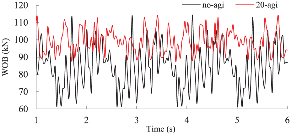
The simulation results of dynamic WOB during drilling with and without an agitator.
The agitator’s optimal installation position
To investigate the optimal installation position of the agitator, the ∅172 mm agitator was selected, and the installation positions of the agitator were set 20, 100, 200, 300, 400, 500, and 800 m away from the bit, respectively. The simulation of the BHA dynamic response was carried out. The ROP, dynamic WOB, and axial frictional drag during the drilling process are shown in Figures 4–6, respectively.

ROP with an agitator installed at different locations.

WOB curves with an agitator installed at different locations.
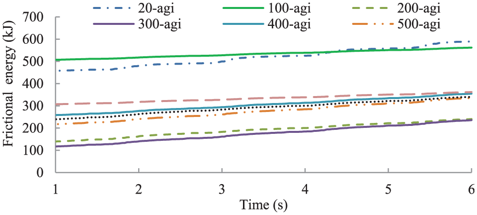
Frictional energy between the drill string and the borehole with an agitator installed at different positions.
The rock model is defined as homogeneous and isotropic, and the influence of failure fragments on the subsequent drilling is ignored in the simulations. The magnitude of ROP obtained from numerical simulation is higher than that of the actual ROP, but its change rule is consistent with the actual drilling process. From Figure 4, the ROP is the maximum when the agitator is installed at [200, 300] m away from the bit. The ROP is 31.54 m/h for drilling without an agitator, and a value of 48.09 m/h is observed for drilling with the agitator installed at [200, 300] m away from the bit, with an increase of 52.47%.
From Figures 5 and 6, the dynamic characteristics of the bit have significant differences when the agitator is installed at different locations. It can be seen from Figure 5 that the WOB is the largest and the transfer rate of axial force is the highest when the agitator is installed at [200, 300] m away from the bit; these values will lead to the best effect on the drilling process. Figure 6 shows the friction energy between the drilling string and the borehole with the agitator installed at different locations during the drilling process, which reflects the frictional drag between the drill string and the borehole. The frictional drag increases with the increase of friction energy, and vice versa. The frictional drag will be reduced significantly if the agitator is installed at certain position; the loss of axial force is the minimum when the agitator is installed [200, 300] m away from the bit. This will not only increase the ROP and the extended limit of the horizontal well, but also decrease the probability of buckling in the drilling string. The optimal installed position of [200, 300] m away from the bit is recommended for the ∅172 mm agitator.
The agitator’s influence on the BHA vibration
This section discusses the influence of the agitator on the vibration characteristics of BHA during the drilling process including the vibration and buckling under two different situations without and with an agitator installed 200 m away from the bit. Figure 7 shows the lateral acceleration of the near-bit during the drilling process without an agitator. Figure 8 shows the lateral acceleration of the near-bit during the drilling process with an agitator installed 200 m from the bit. The results show that the use of an agitator in the drilling process will not intensify the lateral vibration of BHA and the vibration of BHA inversely is weakened slightly. The virtual acceleration (root mean square (RMS)) of the lateral vibration at the near-bit is approximately 1.6g when drilling without an agitator. On the contrary, the value is 1.4g in the drilling process with an agitator installed 200 m away from the bit. Both conditions are safe according to the vibrational grade standards of BHA formulated by Baker Hughes (Table 3).20,21 The drilling tools are under safe conditions and it is safe to continue drilling. Therefore, the agitator in the drilling process does not affect the lateral vibration of BHA or the safety of drilling.

Lateral vibrational response curves of the near-bit during the drilling process without an agitator.
Lateral vibrational response curves of the near-bit during the drilling process with an agitator installed 200 m from the bit.
Lateral vibrational grades in drilling of Baker Hughes.

The displacement with respect to time at one certain node of the drilling string is plotted in Figure 9, and the results without and with an agitator installed 200 m away from the bit are monitored. The results observed from the simulation both with an agitator installed 200 m away from the bit and without an agitator in the drilling process show the phenomenon of spiral buckling. However, Figure 9 shows that the amplitude of the lateral twist and spiral bucking of BHA in the drilling process with an agitator is reduced compared to that without an agitator. The occurrence probability of BHA bucking can be effectively reduced using an agitator in the drilling process.

The BHA bucking without and with an agitator installed 200 m away from the bit.
The agitator’s optimal working parameters
The vibration frequency and impact load of the agitator are the most important parameters when designing an agitator, which are also the most important factors in the operation of the agitator during the drilling process. To determine the optimal frequency and impact load of the agitator, the influence of vibration frequency and impact load of the agitator on the BHA dynamic characteristics is analyzed. The numerical model of various vibration frequencies of 3, 10, 15, 17, 19, 22, and 25 Hz is simulated, and the corresponding results are plotted in Figure 10. The vibration frequency of the agitator has a certain effect on the rock breaking efficiency, and the ROP will reach its maximum value when the vibration frequency of the agitator is 17 Hz.

Relationship of vibration frequency and penetration displacement.
The ROP rising percentages under various vibration frequencies of the agitator are depicted in Figure 11, the ROP increased more than 40% when the vibration frequency is between [3, 17] Hz, and the variation is relatively small. Therefore, the vibration frequency of the agitator has a small effect on the ROP increase when the frequency is less than 17 Hz. The ROP will drop to 30% when the vibration frequency is larger than 17 Hz.
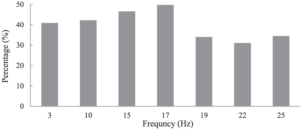
The relationship between vibrational frequency and ROP increase.
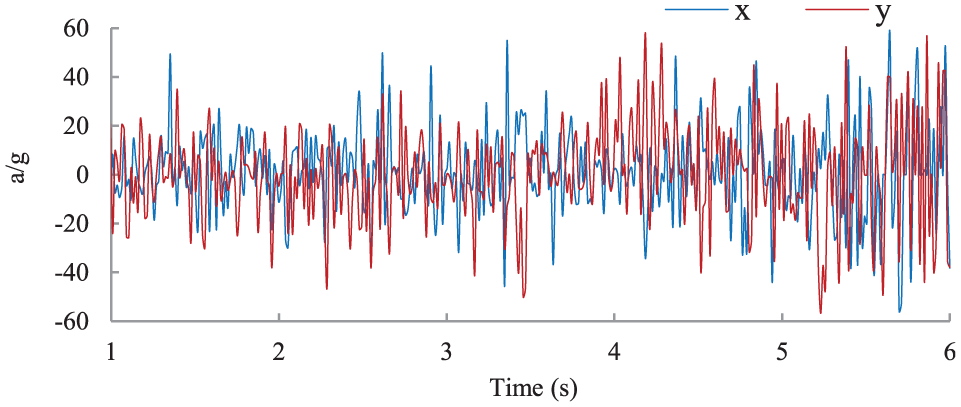
Figure 12 shows the effect of different vibration frequencies of the agitator on the BHA lateral vibration in the drilling process. According to the grades of the BHA lateral vibration formulated by Baker Hughes, the range of [0, 2g] is safe, [2g, 5g] is moderate, and the vibration is severe when the virtual value of the lateral acceleration is greater than 5g. From Figure 12, the lateral acceleration (virtual value) of the BHA is less than 2g, in a safe state unless the vibration frequency of the agitator exceeds 17 Hz. The lateral acceleration (virtual value) of BHA is 2.9g when the vibration frequency of the agitator is 19 Hz in a moderate state. It is necessary to measure the lateral vibration of the BHA in real time if we continue to drill at this time. The lateral acceleration (virtual value) of BHA is 7.8g (much larger than the alarm value of 5g) in the drilling process when the vibrational frequency of the agitator is 22 Hz in a severe state. It is very dangerous when the lateral acceleration in the drilling process is greater than 5g, which must be avoided. Based on the comprehensive consideration of the vibration frequency effect on the ROP and lateral vibration of BHA, the optimal frequency is 17 Hz and the selected frequency should be less than 17 Hz when designing an agitator to reduce the vibration of the BHA in the drilling process.
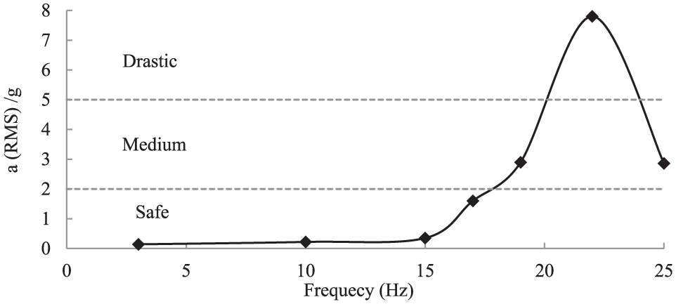
Lateral acceleration (RMS) of BHA with vibrational frequencies of different agitators.
The effect of the impact load on the drilling process is observed; three different impact loads (50, 100, and 150 kN) of the agitator are selected to analyze its influence on the rock breaking efficiency and dynamic characteristics of BHA. Figure 13 shows the relationship between the impact load of the agitator and ROP. Figure 14 shows the dynamic characteristics of the BHA in the drilling process when the impact load is 150 kN. From Figure 13, the impact load of the agitator has a great influence on the rock breaking efficiency, and the ROP increases with the increase of impact load. It can be seen from Figure 14 that the lateral vibration of the BHA rapidly increases when the impact load is 150 kN, as well as when the lateral acceleration (virtual value) of the near-bit is 8.04g and is in a severe state. This must be avoided in the actual drilling process. From Figure 8, the vibration of the BHA decreased significantly (the virtual value of acceleration is 1.4g) when the impact load of the agitator is 100 kN. The optimal impact load is 100 kN.
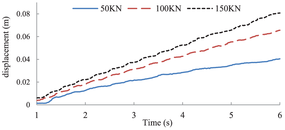
Relationship between the impact load of the agitator and penetration displacement.

Lateral vibrational response of the near-bit when the impact load is 150 kN.
Field application cases
An agitator setup is used in the Chu 26-12x well drilling designed by CNOOC Energy Technology Drilling and Production Company as shown in Figure 15. From the simulation results discussed above, the installation position of the agitator is selected to be 200 m away from the drill bit and the vibration frequency of 12 Hz is used in Chu 26-12x well drilling. The BHA used in the drilling is as follows: ∅216 mm PDC bit+∅172 mm PDM+∅204 mm stabilizer+float valve+∅165 mm NMDC+no magnetic sub+∅165 mm NMDC × 2 +∅127 mm heavy weight drill pipe (HWDP) × 17+∅172 mm agitator+∅127 mm HWDP × 5+∅165 mm hydraulic jar+∅127 mm HWDP × 2+∅127 mm DP. The hook loads of the two different sections in Chu 26-12x well drilling which have the same drilling condition and BHA are compared as shown in Figure 16.
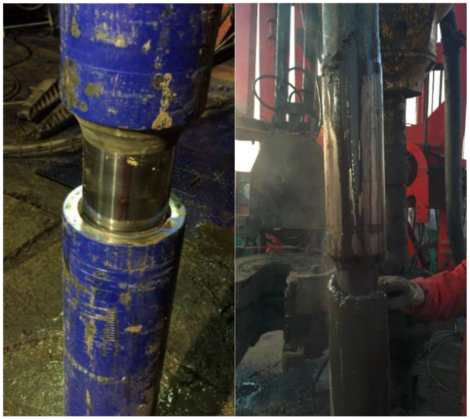
The field application of the agitator.
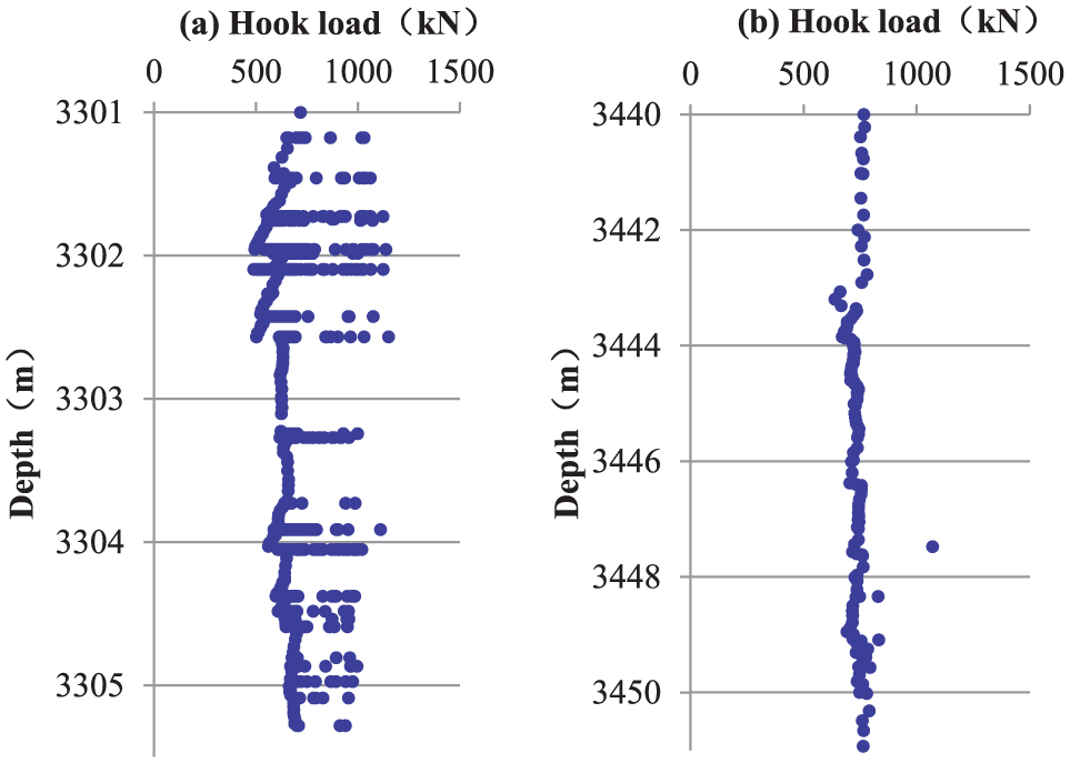
The hook load versus drilling depth (a) without and (b) with an agitator.
The magnitudes of hook loads during slide drilling from 3301 to 3305 mm without the agitator are plotted in Figure 16(a). During the drilling process, the sliding friction resistance is 15 tons, the sliding tropsh-pressure is 15 tons, the WOB cannot be effectively transmitted, and the drilling tools need to be moved up and down frequently. The magnitudes of hook loads during slide drilling from 3301 to 3305 mm with the agitator are plotted in Figure 16(b). The hook load measured during slide drilling is stable, as well as the WOB transmission. The sliding friction resistance force is reduced to 11 tons, and no tropsh-pressure is observed. Figure 17 shows the ROP during drilling with and without an agitator. The ROP is slow with the average value of 1.66 m/s without an agitator. However, the average value of ROP is sharply increased from 1.66 to 4.89 m/s. The frictional drag and tropsh-pressure will be reduced and the ROP will be increased while using the agitator in the drilling process.
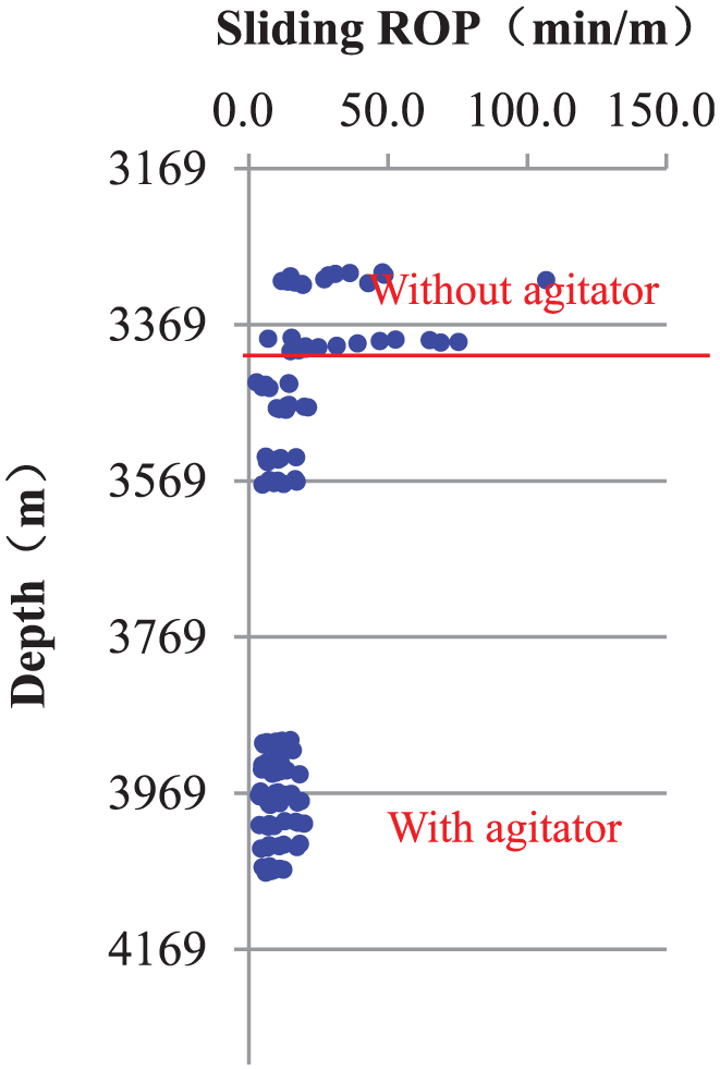
The rate of penetration while drilling with and without an agitator.
Conclusion
This study presented a series of numerical simulations to investigate the working mechanism and parameter optimization for the agitator, and the field application of agitator is also discussed based on the numerical results for the agitator design and drilling parameter optimization. The following conclusions can be summarized:
Due to axial excitation of the agitator, the static friction between the drilling string and borehole wall is changed into sliding friction, which excites the drilling tools to keep the axial movement. The working conditions of the drilling tools and the WOB transmission efficiency will be improved, and the fluctuation of WOB becomes significantly weakened and smoothened. The frictional drag and occurrence probability of drilling string buckling will be reduced greatly.
The optimal installation position of the ∅172 mm agitator simulated in this study is [200, 300] m away from the bit, the optimum frequency is [3, 17] Hz, and the optimal impact load is 100 kN.
The field application of agitator is discussed. The agitator is recommended to be installed 200 m away from the drilling bit and the recommended frequency and impact load are 12 Hz and 100 kN, respectively. The results of field application show that, compared with a scenario without the agitator, the frictional drag and tropsh-pressure will reduce and the ROP will increase using an agitator in the drilling process.
This study leads to a better understanding of the working mechanism of the agitator and contributes to the improvement in agitator’s design and the parameter optimization.
Footnotes
Acknowledgements
The authors are grateful to the University of Regina for its support toward the completion of the research.
Handling Editor: James Baldwin
Declaration of conflicting interests
The author(s) declared no potential conflicts of interest with respect to the research, authorship, and/or publication of this article.
Funding
The author(s) disclosed receipt of the following financial support for the research, authorship, and/or publication of this article: This study was supported by China Postdoctoral Science Foundation (2017M612918 and 2018M633403), Chongqing Postdoctoral Research Project Special Funding (Xm2017111), Scientific Research Starting Project of SWPU (2018QHZ015), and Applied Basic Research of Sichuan Province (Free Exploration-2019YJ0520).