
Abstract
To avoid the failure of mandrel-type casing hanger, this article provides a new type of metal sealing structure, and the sealing is achieved through plastic flow of soft metal and elastic deformation of matrix. A finite element analysis model for sealing performance of mandrel-type hanger is established to study the deformation and contact pressure of sealing cone. Among the four sealing structures studied in this article, the elliptic surface is the optimal. It is suggested to design smaller equal cone angle of inner cone angle (β) and outer cone angle (α) in the limited space as far as possible so as to obtain larger average contact pressure. These findings can provide references for the structural design of the seal area of the mandrel-type hanger. The sealing test results show that the sealing curve turns to be a straight line under water pressure and air pressure of 140 MPa. The results of theoretical study and laboratory experiment show that the sealing structure of full-metal multilevel conical elliptical surface is reliable and can meet the sealing requirements of the oil field wellhead device under limit working condition of 140 MPa.
Introduction
Most of the commonly used hanger sealing systems are of rubber, which have poor performance in high and low temperature resistance, corrosion resistance, aging resistance, and short service life, and cannot meet the sealing requirements of wellhead under high temperature and pressure. Failure of wellhead seals will lead to production reduction and maintenance cost increase of oil and gas wells and will also cause enormous safety and environmental problems. According to statistics, up to 18% of offshore oil and gas wells in the world have problems in wellhead sealing integrity. 1 The eccentricity of casing sting will further result in cumulative wear failure of casing inevitably. 2
The conventional hanger is mainly composed of metal and rubber sealing structure (as shown in Figure 1). The annular space between the cross joint and the mandrel is sealed through squeezing the H-type rubber and X-type metal sealing rings by the pressure of upper plug and the suspension load of casing string, where the downhole casing string is suspended by the pressure of upper top ring and the lower threading. In order to avoid the failure of mandrel-type casing hanger, a new type of metal sealing structure is designed to solve the contact problems in relevant sealing structures.

Schematic diagram of mandrel-type hanger.
In recent years, experts and scholars have done a lot of research on the structure of metal seal. GR Murtagian and ZQ Gong3,4 studied the empirical function relation between sealing performance of static metal-to-metal sealing surface and sealing contact stress profile by means of physical experiments and numerical simulation, which can be used to evaluate the sealing performance of metal-to-metal. The elastic contact is extended to the elastic-plastic contact, which changes the ratio of yield stress to elastic modulus and the strain hardening rate. The relations among contact area, morphology, pressure distribution, and load are discussed, and the relation between the wide range of surface and the material properties is revealed. 5 The contact between rough surfaces is assumed to be an elastic-plastic contact between a plastic micro-convex body and a fully elastic plane. The distribution of contact pressure and the size of contact area are calculated. 6 By establishing the contact statistical model between the micro-convex body with elastic-ideal plasticity and the rigid plane, the prediction of contact area and contact force is realized. 7 S Wang and Komvopoulos 8 and HK Müller and Nau 9 established a theoretical model of gas leakage rate in metal-to-metal sealing structure based on laminar flow theory of incompressible viscous fluid, which provides a theoretical basis for revealing the nature of gas flow in metal-to-metal seal gap, quantitatively evaluating the sealing performance of metal-to-metal contact and optimizing the sealing structure parameters. A Majumdar and Bhushan10,11 found that the contour of metal sealing surface can be characterized by Weierstrass-Mandelbrot function in fractal geometry, which is continuous, non-differentiable, and self-affine everywhere.
L Milberger and Radi12,13 proposed a new type of wellhead device for full-metal sealing of casing hanger and gave a sealing test method. In addition, this article will provide a reference for the analysis of sealing pressure test.
The above scholars have done a lot of research on the structural reliability and stress analysis of the casing head, which has important reference value for the structural design of the casing hanger. However, there are few literatures in view of the sealing failure caused by the aging of rubber seal or the erosion of corrosive medium in the wellhead hanger of ultra-deep, high-temperature and high-pressure gas wells, as well as the theoretical research on the metal seal of the mandrel casing hanger; the papers give the corresponding analysis and solution to the leakage and sealing failure of gas production wellhead and surface pipeline, and it provides corresponding measures for safe operation and environmental protection of natural gas development.14–17
Therefore, this article provides a 280-type sealing system for mandrel casing hanger and proposes to change the rubber sealing structure of the existing casing hanger into a tapered metal sealing structure. The simulation and experimental study on mechanical mechanism of metal contact sealing, and the sealing structure are carried out to provide a reference for full-metal tapered sealing structure of mandrel hanger.
Structure of mandrel casing hanger
In China, BT seal (rubber sealing ring) or slip seal failure of casing hanger has occurred more than 30 times ultra-high-pressure gas wells in Kuche Piedmont, Tarim, causing huge economic losses and potential safety hazards to the oil field. Because the rubber sealing ring is used in the existing mandrel hanger device, aging will occur after long-term use in the harsh environment such as high temperature and high pressure in the well site, resulting in gas leakage from the sealing gap, and high-pressure gas flow will enter the annular space gap from the bottom of the well, causing safety accidents.
The sealing structure of conventional mandrel hanger used in the field is subject to perennial compression load and drastic temperature change, which makes the rubber parts easy to aging. In the process of sealing test, the main seal failure often occurs, as shown in Figure 2. Rubber seals may perform well in a short time, while plastic deformation and aging will occur under the harsh environment of a long time, losing the sealing effect of rubber seals.

Structure of mandrel and failure of rubber ring on site.
Design of sealing structure for mandrel-type casing hanger
In order to reduce gas leakage accidents and prevent rubber aging failure, this article introduces the improvement of the existing sealing structure, proposes different types of curved-surface sealing structure, and then compares the sealing contact pressure and sealing contact width of four sealing structures, so as to find a more reasonable curved surface of sealing structure, and carries out processing and field tests. Therefore, the research and design of sealing structure of 280-type mandrel-type casing hanger are mainly described below. It is proposed that the rubber sealing structure of the existing casing hanger should be changed into a conical metal sealing structure.
Design for sealing structure system
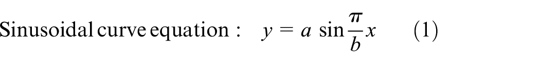
The three-dimensional solid structure and local enlargement of the overall structure are shown in Figure 3(a). The sealing structure is mainly composed of cross joint, mandrel, pressing ring, butterfly spring, and seal ring. Figure 3(b) is a schematic diagram of the structural dimensions of the sealing cone, which is composed of the upper seal and the lower seal. Based on the metal seal of ocean flange and the sealing form of spherical and conical surface in special-thread sealing structure of fastener,18,19 and investigation of static and dynamic seal performances of a rubber ring and the sealing form of spherical surface, 20 four sealing structures of linear, sinusoidal, elliptical, and parabolic surface of mandrel casing hanger are designed and analyzed in this article. The geometric parametric equations of sinusoidal, elliptic, and parabolic curves equation are shown in formulas (1)–(3)
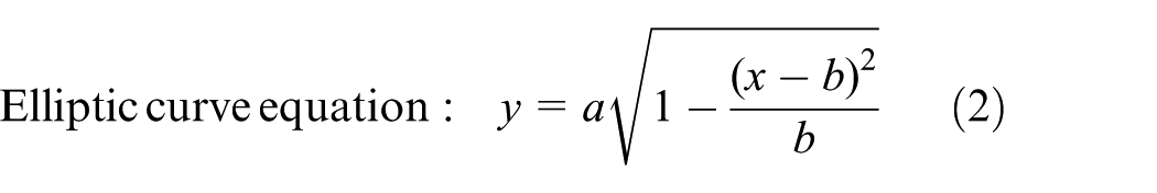

The key parameters a and b of the above formulas are shown in Figure 3(b). The main dimensions of the sealing cone are a, the curve amplitude; b, the curve width; c, the distance; and d, the groove depth at the root of the curve. Through finite element analysis and research, it can be seen that the wider of the sealing surface is, the smaller the contact pressure is, and vice versa. The structural dimensions of the contact surface of the linear sealing cone can be adjusted and optimized to ensure adequate sealing pressure.
(a) Structure of mandrel-type hanger and (b) dimensions of sealing cone.
For curved-surface seals, the structural dimensions are a = 2 mm and b = 25 mm. The contact curve shape and contact area are shown in Figure 4. When a and b are the same, the elliptic contact area is the largest, followed by the parabola, and the sinusoidal contact area is the smallest. Therefore, to obtain the widest contact area, the elliptic curve is the optimal. If the maximum contact pressure is considered, the opposite is true. Comparing these three kinds of sealing curves, the sinusoidal curve structure can be used if the contact pressure is the greatest, and the elliptic curve structure can be used if the contact width and pressure of the sealing surface are larger.

Shapes of different contact curves and contact areas.
Pressure applied to an elliptical region
Two non-confirming bodies loaded together make contact over an area which is elliptical in shape, so that the stresses and deformation due to pressure and traction on an elliptical region are of practical importance. 21 We are led to consider pressure distributions of the form

where p is the contact pressure of sealing surface, MPa;
Which act over the region bounded by the ellipse

The classical approach, using the potential function of Boussinesq, is usually followed. Thus, by equation (6)


where


where
It then follows from potential theory that for a general point in the solid

Hertz pressure (n = 1/2).
In this important case, the pressure is

Thus

and on the surface, within the loaded region

where w is the contact width of sealing surface, mm.
The surface displacement within the loaded region may then be written as

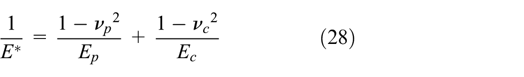
where E is the modulus of elasticity (MPa)


and
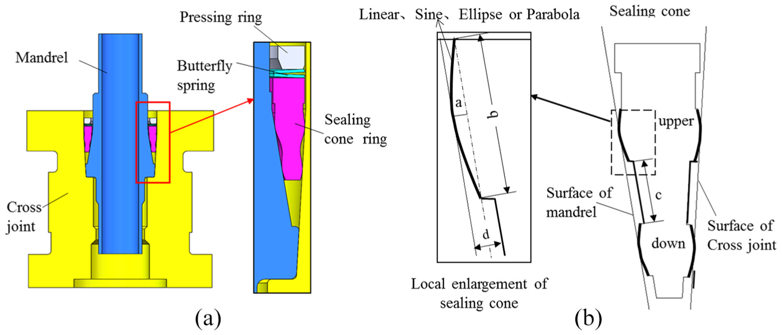
The total load acting on the ellipse is given by
The epileptic integrals


and along the y-axis

where
At the center


where
Outside the loaded ellipse, the surface stresses are equal and opposite, that is, there is a state of pure shear
and

where
Contact stress of conical and elliptic seals
The sealing structure of elliptical to conical surface has non-conforming contact mechanics. When the pressing ring excites the upper seal ring, the elliptical and conical surfaces of the seal ring first contact with the circumferential line (with the initial contact point) as the radius. With the further injection of high-pressure gas, the elliptical and conical surfaces will generate normal interference, the normal extrusion contact force. When injecting high-pressure gas, the contact surface can reach a certain contact seal width, thus realizing the seal performance.19,21
In order to obtain the normal contact stress, the contact sealing surface is cut through the cross section of the cross joint (or mandrel) and the seal ring axis. Then, the sealing structure of elliptic to conical surface can be simplified as a two-dimensional contact mechanics problem between the cylinder and the plane, as shown in Figure 5. Solving normal contact stress
Cross joint (or mandrel) and sealing face of sealing ring are continuous and uncoordinated;
Cross joint (or mandrel) and seal ring are small strain deformation;
Cross joint (or mandrel) and sealing ring structures are considered as elastic half-space bodies;
Ignore friction between cross joint (or mandrel) and sealing ring contact surface.
Assuming the radius of the ellipse is

where h is the normal clearance of the initial contact between the elliptic and conical surfaces, mm;

Sealing structure diagram of elliptical to conical surface: (a) initial contact and (b) final contact.
After normal interference contact, the cross joint (or mandrel) and the seal ring squeeze each other to produce normal contact pressure, which makes the contact surface of the cross joint (or mandrel) and sealing ring displace along oy, the size of which is

where
The derivation of equation (24) is obtained as follows
When the tangential friction force is ignored, the contact mechanics theory shows that

Substitute formula (26) into formula (25)

where
Formula (28) is a singular integral equation of the first kind concerning
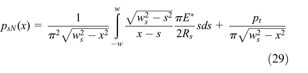
where
The total load

where

According to the theory of contact mechanics, the relation between the contact width

Taking formulas (28) and (32) into formula (31), considering that the elastic modulus and Poisson’s ratio of cross joint (or mandrel) and the sealing ring vary little, it can be approximated that

Finite element analysis of sealing structure of mandrel hanger
Establishment of finite element model
The sealing structure of mandrel hanger mainly consists of three parts: mandrel, sealing cone, and cross joint. For the sealing structure of mandrel hanger, its geometric structure and load are axisymmetric. Based on elasticity and finite element theory, the stress problem of mandrel hanger sealing system can be simplified to axisymmetric finite element model. The finite element model and grid division are shown in Figure 6. The dimensions of mandrel hanger are shown in Figure 6(a), where conical seal of cross joint and sealing conical surface (linear, sinusoidal, elliptical, and parabolic) are marked. The grid division of the mandrel, cross joint, and its different sealing cones is shown in Figure 6(b). The sealing contact area has denser grid division to improve the accuracy of calculation.

(a) Mechanical model of seal system and (b) grid division of sealing system.
Various parameters include outer conical angle of seal (α), inner conical angle of seal (β), upper seal width (b1), lower seal width (b2), the seal spacing of upper and lower (c), the maximum width of sealing cone (BB), the height of sealing cone at different positions (H and h1), and long and short half axles of sealing conical surface (b and a, respectively). The data of the initial structural parameters are shown in Table 1. The structural parameters of the sealing cone are optimized and analyzed in a finite space based on these parameters.
Basic structural parameters of sealing cone.

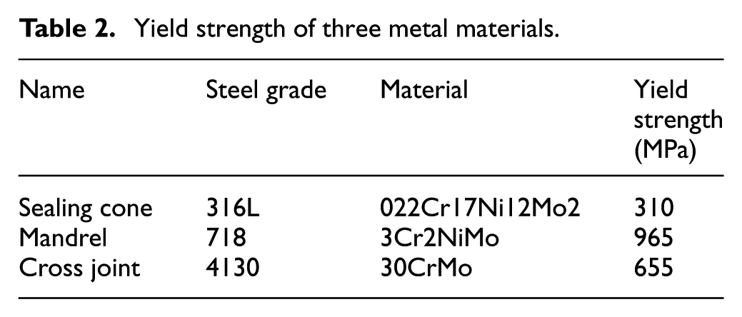
According to formulas (1)–(3), the annular space structure size between the mandrel and the cross joint is calculated as shown in Table 1. In this article, the sealing system of mandrel hanger is mainly composed of mandrel (718), sealing cone (316L) and cross joint (4130). The elastic modulus and Poisson’s ratio of the three parts are 2.1E5 MPa and 0.3; the yield strength of the three materials is shown in Table 2. The mandrel and cross joint are of high-strength alloy steel, and the sealing ring is of soft metal. Its sealing principle is realized through plastic flow of soft metal and elastic deformation of matrix.
Yield strength of three metal materials.
Finite element analysis of sealing structure
According to the finite element model of the full-metal sealing system established in this article, five contact seals located in Pc1, Pc2, Pc3, Pc4, and PC5 are shown in Figure 6(a), respectively. Fixed displacement constraints are imposed on A1B1 at the lower end of the cross joint connection. P1 is the casing hanger applied to E at the lower end of the mandrel, and P2 is the pressing ring applied to CD surface at the upper end of the sealing cone. In the model, the inner cone angle, α, is 9° and the outer cone angle, β, is 3°. In the process of simulating the loading process of actual working conditions in the field, the maximum casing hanger weight P1 = 400t is applied to E of the mandrel.
Relation between contact pressure and path of seal cone surface
When the exciting pressure P2 applied on the sealing cone is 10t according to Figure 6(a), the maximum contact pressure of the linear cone, sinusoidal surface, elliptic surface, and parabolic surface is 150.5, 429, 307.3, and 389.4 MPa, respectively, through finite element simulation calculation, as shown in Figure 7.

Contour of contact pressure of sealing cone: (a) liner, (b) sine, (c) ellipse, and (d) parabola.
The relation curves between contact pressure and paths of different seal cones are shown in Figure 8(a)–(d). It is found from the figures that the four kinds of contact seals have the same curve amplitude; the contact area of the linear surface is larger than that of the non-linear surface, which results in a contact pressure of the linear contact surface less than that of the other three kinds of curved contact surfaces.

Relation curves between contact pressure and path of different seal cones: (a) liner, (b) sine, (c) ellipse, and (d) parabola.
The contact pressure on the four surfaces of the linear sealing cone is U-shaped, that is to say, the contact pressure in the middle of the four cones is smaller, while the contact pressure at the two ends of the contact surface is larger. For the contact pressure of the other three kinds of sealing cones (ellipse, parabola, and sine), it can be seen that the contact seal widths are ellipse, followed by parabola and sine under the same conditions. The contact pressure on the inner cone surfaces (Pc2, Pc3) is larger than that on the corresponding outer cone, so the inner and outer cones can be adjusted to ensure the sealing performance. If the maximum contact pressure and width are considered, the sinusoidal curve structure can be used; if the maximum contact pressure and the width of the contact surface are considered, the elliptic surface structure can be used.
Tables 3–5 are the calculation results of average contact pressure, average contact width, and average contact energy on four contact sealing surface paths Pc2, Pc3, Pc4, and PC5 in Figure 8, respectively. The contact energy is equal to the product of contact pressure and contact width. From Tables 3–5, the following conclusions can be drawn:
In terms of contact pressure, the parabola surface is the maximum, followed by elliptic and sine, as shown in Table 3.
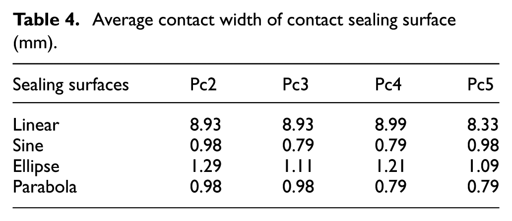
In terms of contact width, the elliptic surface is the widest, followed by parabola and sine, as shown in Table 4.
In terms of contact energy, the elliptical surface is the best, as shown in Table 5.
Average contact pressure of contact sealing surface (MPa).

Average contact width of contact sealing surface (mm).
Average contact energy of contact sealing surface (MPa.mm).

Among the four sealing structures in this article, the elliptic surface is the optimal.
Analysis of cone angle and contact pressure
It was found that the inner cone angle and the outer cone angle were very sensitive to the contact pressure in the previous finite element model calculations. Therefore, when the outer cone angle α is 3°, the inner cone angle decreases gradually. The relation between the average contact pressure and the average contact width at different inner cone angles with the pressure of pressing ring is obtained. It can be seen from Figure 9 that the average contact pressure and the average contact width on the sealing contact surface increase with the increase of the pressure of pressing ring, as shown in Figure 9. When the outer cone angle α is 3°, the average contact pressure and the average contact width increase with the decrease of the inner cone angle. Therefore, in order to obtain a larger contact pressure, a smaller inner cone angle should be designed as far as possible to improve the sealing ability.

Variation of contact pressure and width with the inner cone angle and P2.
Based on a large number of finite element simulation calculations and analysis, it is suggested to design smaller equal cone angle of inner cone angle (β) and outer cone angle (α) in the limited space as far as possible in order to obtain larger average contact pressure in the limited annular space of cross joint and mandrel. Therefore, a full-metal sealing ring with equal conical angle (α = β = 3°) is proposed as the final optimization scheme.
Design of sealing structure of elliptical surface
Four kinds of sealing structures are calculated by the finite element method in section “Finite element analysis of sealing structure of mandrel hanger.” The results show that the elliptical metal seal has the best performance. Then, the elliptical sealing structure is selected for trial manufacture. The sealing performance of the elliptical sealing structure is experimentally studied to verify the advantages of the elliptical sealing structure designed in this article. As shown in Figure 10, the sealing parts of the mandrel hanger are mainly composed of double U-shaped elliptic metal sealing ring (referred to as double U), single U-shaped elliptic metal sealing ring (referred to as single U), mandrel, and cross joint. The sealing mechanism of this structure is that the elliptical metal seal ring is pressed tight to the contact surface by the suspension load and the pressure to the inlet, so that the two elliptical surfaces of the elliptical metal seal ring are in interference fit with contact surfaces of the mandrel and the cross joint, thus realizing the function of metal seal.

Schematic diagram of mandrel hanger assembly and metal seal ring.
Given that hydraulic cylinder diameter D = 350 mm and piston diameter d = 200 mm, P is the hydraulic pressure, MPa. The hydraulic pressure corresponding to tension F of pull rod can be obtained from the following formula (34)
By substituting the data, the hydraulic pressure of 62 MPa is obtained, corresponding to the pull rod force of 4015293.6 N, that is, 401.53 ton of downward pull force. During the sealing test, 62 MPa was loaded on the hydraulic cylinder, that is to say, 401 ton of tension were applied to the lower part of the hanger, and the pressure was pumped from the test port shown in Figure 10. Pumping pressure of double U and single U through pressure test port is shown in Figure 11.

Sealing test process diagram of double U and single U.
Experimental study on elliptical metal seal ring
Hydraulic sealing test
After assembling the mandrel and the upper and lower metal sealing rings according to Figure 12, inject the pressure oil of about 62 MPa into the flow passage of the hydraulic cylinder, and then the pressure test pump is opened. Metal seals can be tested by injecting water pressure into test ports of double U and single U, respectively. The measurement range of pressure test pump and its pressure gauge is 0–250 MPa. The pressure gauge on the pressure test pump should have the accuracy of 0.5%. The measured pressure ranges from 25% to 75% of the gauge range.

Sealing test device and pressure gauge.
The test results of Figures 13 and 14 show that the sealing requirements can be met by applying a staged pressure up to 140 MPa for both double U and single U sealing rings. For double U, the pressure is injected from annulus space A with a pressure stabilization of 30 min; for single U, the pressure is injected from its top with a pressure stabilization of 60 min. Both sealing rings have no leaks occurred. The results show that the performance of metal seals under ultra-high water pressure is stable.
Test curve of double U under hydraulic pressure.

Test curve of single U under hydraulic pressure.
Pneumatic sealing test
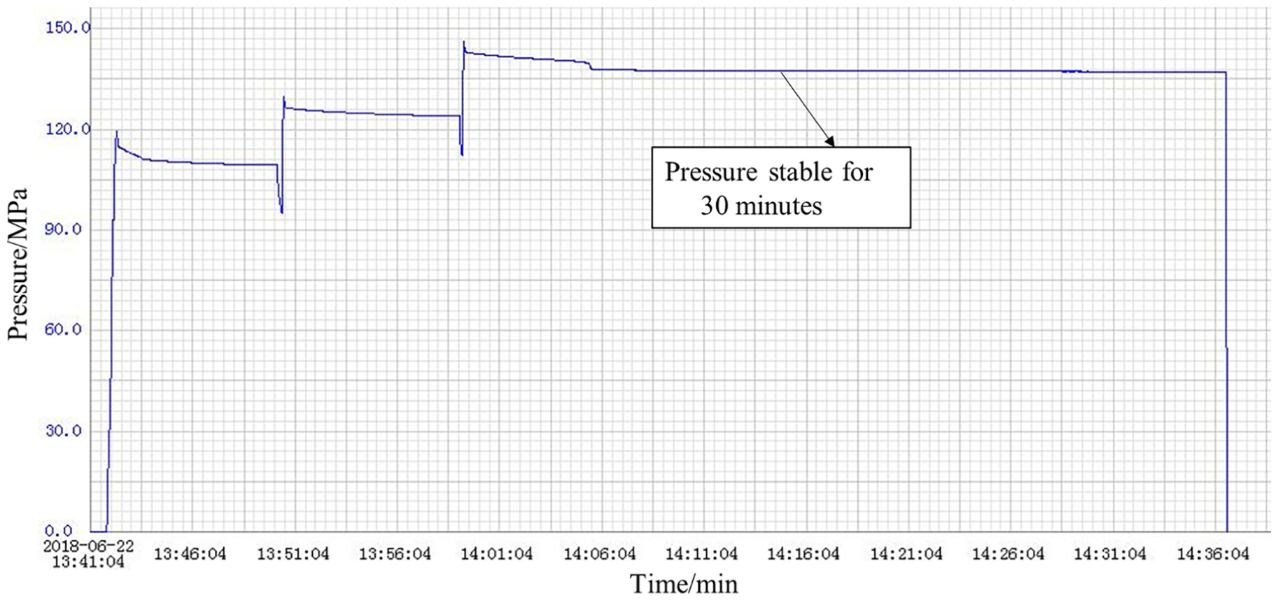
First, a pressure cycling test of 140 MPa is carried out in the annulus space formed by double U and steel ring, pressing ring, and upper cross joint. The test pressure is not less than 140 MPa, and the holding time after each pressure stabilization should not be less than 15 min. The test medium is nitrogen. The pressure drop less than 3.45 MPa during the voltage stabilization period is deemed as qualified. After each test, the pressure should be released to 0, the rebound should not be less than 140 MPa, the pressure should be stabilized for 15 min, and the pressure drop should not exceed 2.5 MPa. The test should be terminated in case of leakage. Repeat these steps 20 times. The pressure test is recorded and 20 test curves are obtained. The pressure test process curve as shown in Figure 15 is selected. It is observed that the sealing curve approximately turns to be a straight line, indicating that the double U sealing ring performs well.

Test curve of double U under nitrogen pressure.
Then, loosen the plug, make the double U sealing ring in the state of loosening, and apply pressure to the second pressure test hole. The single U and the annulus space formed by the steel ring, pressing ring, and upper cross joint annulus space are tested by a pressure cycling test of 140 MPa for five times. A 62 MPa pressure is applied by a liquid cylinder in the same way. After pressure stabilization, the holding time should not be less than 15 min. Figure 16 is a pressure test process for five times. The sealing curve approximately turns to be a straight line, indicating that the single U seal ring performs well.

Test curve of single U under nitrogen pressure.
Test analysis and comparison
Through the inspection of the outer and inner sealing surfaces of double U, it is found that the indentation width at the upper side of the outer sealing surface is 5 mm, the indentation width at the lower side of outer sealing surface is 11 mm, the indentation width at the upper side of inner sealing surface is 6 mm, and the indentation width at the lower side of inner sealing surface is 9.5 mm, as shown in Figure 17.

Contact width inspection of double U.
The outer indentation width of the single U sealing ring is 14 mm and the inner indentation width is 15 mm, indicating that the inner and outer sealing surfaces have sufficient contact width for high-pressure gas seal of 140 MPa, as shown in Figure 18.
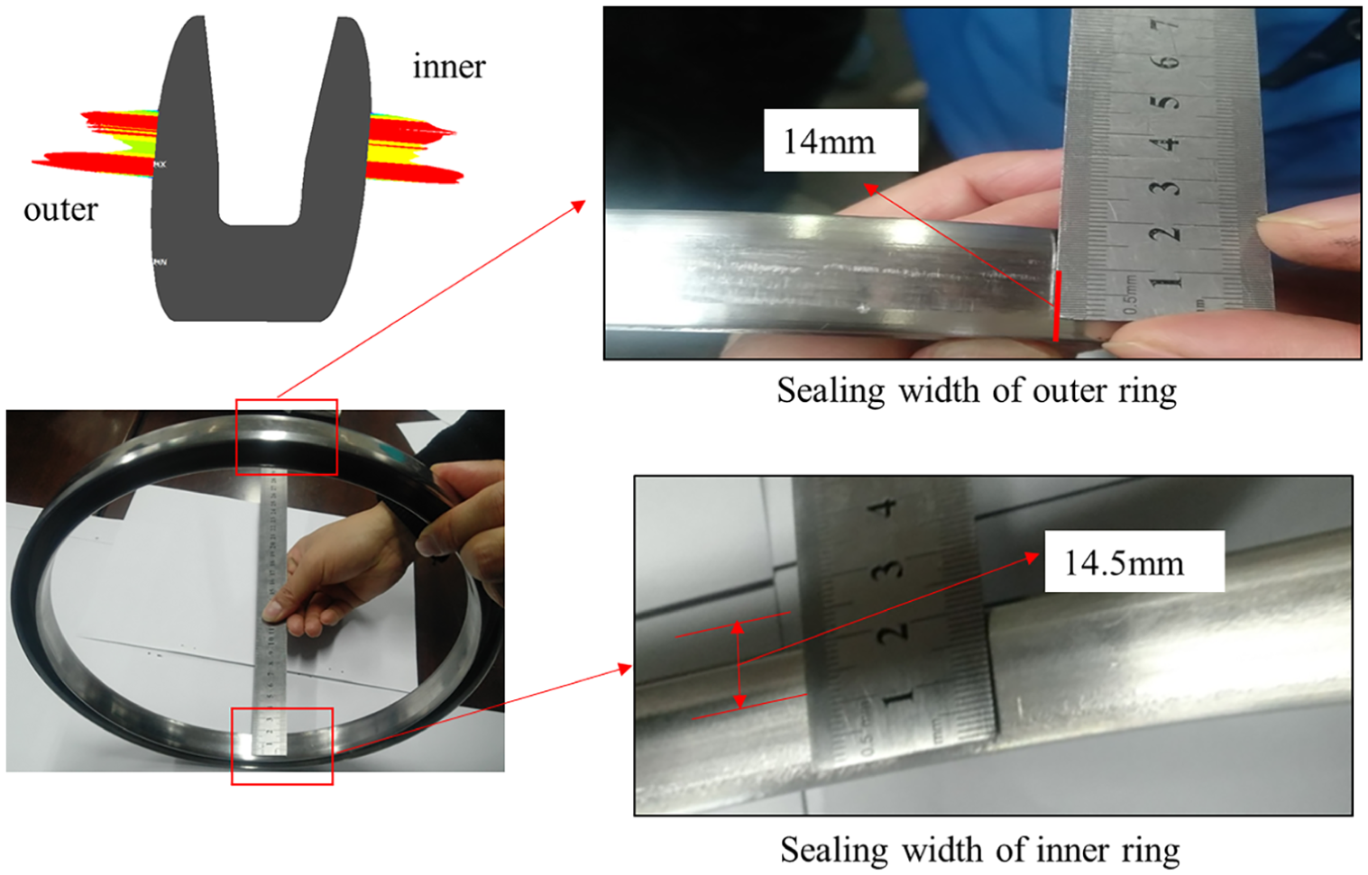
Contact width inspection of single U.
Under this working condition, the contact pressure contour of both double U seal ring and single U seal ring is obtained by finite element calculation (Figure 19). As shown in Figure 18, the maximum contact pressure is 590 and 718 MPa, respectively. The pressure is much higher than the given gas pressure of 140 MPa, and it is favorable to enhance the reliability of seals. Based on the measurement of seal width after pressure test and the calculation results of finite element method, the comparison is made, as shown in Table 6.
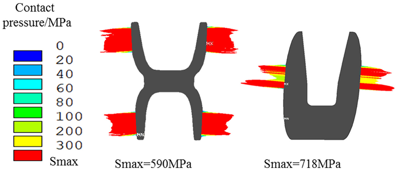
Contour of contact pressure of double U and single U.
Measurement results of sealing width after pressure test.

The test results show that the upper and lower width of the double U seal is 5–6 and 9.5–11 mm, respectively, and that of the single U seal is 14–14.5 mm. The average contact pressure of all sealing surfaces calculated by finite element method is 350–445 MPa, which is 2.5–3.18 times that of 140 MPa. The sealing structure is reliable and innovative and has been certified by a third-party type identification test.
Conclusion
The water pressure and air pressure tests of the elliptical metal seal ring show that the upper and lower sealing structures meet the sealing requirements under the pressure of 140 MPa, so they can be used under ultra-high pressure.
Through the finite element analysis of the contact width and sealing contact energy, it is concluded that the elliptic surface is the optimal sealing structure, and the sealing performance of the structure is the optimal under the limit load.
It is concluded that the inner and outer cone angles are designed as equal cone angles of 3° in the ring space with the limit of cross joint and mandrel, which has the best sealing performance.
Seal width of surface contact relative to line contact increases, which is helpful to reduce the contact stress and avoid premature creep failure of metal seals.
The water pressure and air pressure tests of the elliptical metal seal ring show that the upper and lower sealing structures meet the sealing requirements under the pressure of 140 MPa, so they can be used under ultra-high pressure.
Footnotes
Acknowledgements
Thanks for the efforts of the leaders and technicians of Chongqing Xintai Machinery Co., Ltd. in China, and they worked hard for the precision processing of single U and double U seals. The experimental devices and instruments involved in this article are provided by Chongqing Xintai Machinery Co., Ltd. Thanks for your great help in the smooth writing of our paper.
Handling Editor: Yuejian Chen
Declaration of conflicting interests
The author(s) declared no potential conflicts of interest with respect to the research, authorship, and/or publication of this article.
Funding
The author(s) disclosed receipt of the following financial support for the research, authorship, and/or publication of this article: The authors are grateful to financial support from National Natural Science Foundation of China (nos 51574198 and 51504207). Thanks for the support of project funds from the leadership of Tarim Oilfield Company of China National Petroleum Corporation.