
Abstract
The pipe isolation tool demonstrates remarkable advantages in safety and efficiency compared with traditional plugging devices. However, its utilization in plugging operations is limited by demand of operation duration and precise velocity trajectory. In this article, a pipe isolation tool control system is designed for energy-saving and plugging part’s velocity tracking of the pipe isolation tool. To achieve energy recovery and velocity-tracking control, a flywheel and an accumulator are used for energy transformation and storage. A fuzzy proportional integral derivative controller is proposed to improve the ability of the desired velocity trajectory. The proposed control strategy, compared with the conventional pipe isolation tool drive system, is more energy efficient and has more internally stable dynamics on the closed-loop system. The results verify that both energy-saving and velocity-tracking objectives are satisfied for the electrohydraulic control system of the pipe isolation tool.
Introduction
The pipeline transportation, considered as the best and safest way, has been widely used in long-distance transport of oil and gas productions. 1 With the rapid development of the world economy, the energy demand is increasing, and makes great contributions for faster construction of the global oil and gas pipe network. According to statistics, over 60% of pipelines have been serving more than 20 years, and they have been entered the accident-prone period. 2 Safe and efficient maintenance and repair technology are important ways to ensure the normal operation of these pipelines. Pipeline plugging is the first and most important step in pipe maintenance and repair operations. It can prevent oil and gas leakage and ensure the safety of operating environment. At present, there are three methods to plug the pipe: freeze plug, trepanning, and sealing on nonstop pressured transportation pipeline; and the intelligent plugging technology has been developed in recent years. The intelligent plugging technology does not require inserting holes in the pipe or empty the medium, which can greatly reduce the risk and time required for rush repair. Besides, no additional devices will be left after the completion of the operation, and there will be no potential safety hazard. The intelligent plugging system consists of intelligent plugging device, the surface control center, acoustic modems, an extremely low frequency (ELF) communication link, and remote actuation system, as shown in Figure 1. The pipe isolation tool (PIT) is part of the intelligent plugging device, which is a crucial part of pipeline maintenance during plugging operations.3,4

The diagram of operation process of the intelligent plugging technology.
A number of researches have been done on pipeline plugging techniques over past years. Currently, there are three methods to plug the pipe: freeze blocking, holing and sealing on nonstop pressured transportation pipeline, and the PIT technology. Frozen blocking uses dry ice to cool the outside of the casing and freezes the frozen gel injected into the system. The frozen gel is frozen from the outer casing gradually into the tubing to form a frozen section plug seal ring in order to isolate the pressure in the pipeline.5,6 Trepanning and sealing on nonstop pressured transportation pipeline include opening the hole in the pipe wall and implanting the mechanical plugging device to achieve plugging, which is frequently used in the work of maintenance and repair. It has great capacity of pressure-bearing, and it is available in wide range of pipe diameters. 7 The PIT technology is designed to isolate pressure fluid inside pipelines without losing the contents and reducing the pressure. It can greatly reduce the risk of maintenance operations and work time.8,9
The PIT system consists of PIT module, an (ELF) signal transmitter, signal modems, and control center. Plenty of investigations have been carried out on PIT both experimentally and theoretically. Zhang et al. 10 and Liu et al. 11 designed mechanical structures suitable for different size of pipes, and the experiment showed that the effective mechanism could be plugging. Zhao and Hu 12 optimized the main parameters of PIT module to reduce the vibration caused by the interaction between the pipeline and the PIT in the flow field and improve the stability of the sealing process. In addition, the experiments on the optimized structure were carried out to prove the applicability of the proposed solution. To improve and optimize plugging processes, a number of studies proposed the use of multisensor control systems for monitoring the plugging conditions.13,14 However, due to limited battery life, the PIT cannot run for a long time and so can not be used for remote plugging operation. Until now, the PIT battery is operating for 40 h, and the battery power is 40%. After 60 h of work, it is reduced to 20%. A large amount of energy must be consumed by the battery to provide the ability to follow a desired trajectory. However, the tracking operation needs much lower amounts of work to be done on the environment than the consumed energy. A major issue is how to extend the battery life from hours to days or weeks due to its power consumption.
A number of researches have been done on designing energy-saving and recovery devices, which are widely used in automobile braking, excavator rotation, desalination, and other fields over the past few years. Tokyo R&D Company used supercapacitors on electric vehicles to recover braking energy, which increased the driving range of electric vehicles by more than 20% and extended the battery life by 1.5 times. 15 Komatsu Electronics, Japan, developed a rotary energy-saving hydraulic system, KHER (Komatsu Hydraulic Energy Recycling System). The swing platform rotary brake kinetic energy is stored in the accumulator, and the energy is used in the next rotary start to achieve energy-saving purpose. When swiveling is operated alone or swiveled with a job, the energy generated by swivel braking is stored by the accumulator. The energy is released at the next rotary, reducing the power consumption of rotary and reducing the fuel consumption per unit time. The unit reduces fuel consumption by about 5% per unit time.16–18 The third-generation desalination PX (pressure exchanger) researched by the U.S. company Energy Recovery Inc. has a recovery efficiency as high as 98%.19–21 T. Wang and QF Wang22–24 presented an energy-saving pressure-compensated scheme. It combines a pressure compensator and an energy recovery device together, which can realize effective energy recovery and guarantee good operation of hydraulic cylinders at the same time. Under different working conditions, the total energy recovery efficiency is mainly between 0.26 and 0.33 according to the results. Keivan et al. 25 proposed an energy-saving nonlinear position control strategy for electrohydraulic servo systems. An experimental test of the back-stepping control method was performed and results shown that the position-tracking and energy-saving were satisfied for the closed-loop system. However, to the best of our knowledge, only few papers in the literature tackled the specific issue of velocity-tracking control, and the energy recovery devices on a PIT have not been considered for design and have not been studied.
In this article, an electrohydraulic control system is designed to achieve energy-saving and velocity-tracking of the PIT. For the first time, energy-saving device is added into the PIT system to realize energy recovery and reuse. Moreover, the velocity-tracking control method can greatly reduce the vibration during the plugging process compared with the position-tracking control. An ideal plugging speed model to reduce vibration is proposed. To satisfy the requirements of safe and accuracy, a fuzzy PID (proportional integral derivative) controller is designed to optimize the response characteristics of the closed loop system. The comparisons of tracking error are carried out between square wave reference and sinusoidal wave reference for the fuzzy PID control omitting the energy-saving part. The results show that control strategy has succeeded in realizing velocity tracking. Then, the energy-saving unit is used in the PIT control system. The comparisons of energy consumption are carried out for the speed control and energy-saving of the PIT with and without the energy-saving unit. The energy-saving efficiencies under various operating conditions are obtained to prove the applicability of the proposed method.
System configuration
The energy-saving and velocity-tracking control system is designed in a way to add an energy recovery device consisting of a hydraulic motor, an accumulator, a fuzzy PID controller and a flywheel based on a conventional PIT. The flywheel is installed on the end of the PIT and coaxial with it to avoid local water hammer and the hydraulic control system is installed inside the PIT. The configurations are presented and analyzed as follows.
Typical PIT plugging process
The PIT is an unconventional plugging equipment, which eliminates the need for holes in the pipe for venting of the media. The PIT technology greatly reduces the working risk and time required to repair operations. There is little security risk because there is no additional device left after the plugging process. 3 The schematic diagram of the simplified PIT is shown in Figure 2.

The pipe isolation tool plugging process.
During the plugging operation, the PIT is launched into the pipeline by the launching equipment and moved downstream by the pressure difference between upstream and downstream in the pipe.
When the PIT reaches around the damaged pipe, an ELF signal is sent by the control center through the signal modem to the receiver installed on the pipe wall. The PIT starts to perform plugging action (Stage 1). The hydraulic cylinder drives push tube movement. The push tube pushes sliders along a dovetail groove on the cone tube to squeeze the rubber sleeve. The rubber sleeve expands longitudinally (Stage 2). Until the rubber sleeve and tube wall contact burr, and penetrate to a certain depth, so that the PIT anchors and achieves self-locking. Meanwhile, under the action of pressure sliders, the packing ring becomes thicker radially and makes high-pressure contact with the tube wall (Stage 3). Thus, high pressure medium in the tube is sealed. When the maintenance work is completed, the system pressures relief under the control of the signal. The hydraulic cylinder pressures the relief. The rubber sleeve shrinks under the pressure of the medium in the pipe until the PIT returns to its original state. The PIT continues to move to the receiving end, which is driven by the medium in the pipe and removed by the staff. The plugging operation is completed.
Velocity control system with energy saving of PIT
The important tasks of the PIT are stopping at the required position and plugging to isolate fluid, so the energy recovery unit mainly acts in the first two stages. In the process of plugging operation, the requirements of velocity-tracking control are high, and the water hammer phenomenon can be well reduced compared with the position tracking control. As shown in Figure 3, the PIT velocity control test system is designed with energy saving. The system consists of three parts: PIT model, energy recovery subsystem, and control center. The PIT model includes push tube, sliders, rubber sleeve, and cone tube, as shown in Figure 3(a). Energy recovery subsystem includes accumulator, electrohydraulic control system, hydraulic pump, and flywheel, as shown in Figure 3(b). The control center includes fluid circulation system, data acquisition system, and data communication system. And a test rig is designed to verify the proposed method, as shown in Figure 3(c).

Schematic diagram of velocity control system with energy saving: (a) PIT simplified model, (b) PIT control system, and (c) Test rig.
During the PIT advance, the velocity signal is obtained by the velocity sensors. When the velocity of PIT in the pipeline is less than the fluid velocity, the opening of the speed governor is reduced according to the control signal. The pressure difference between the upstream and downstream of the PIT is increased, which accelerates the PIT to go forward. On the contrary, when the velocity of PIT increases beyond the fluid flow velocity, the opening of the speed governor is increased according to the control signal. The pressure difference between the upstream and downstream of the PIT is reduced, which decelerates the PIT to go forward. Repeat this cycle until the PIT closed to the plugging area. When the pressure sensor indicates that the pressure reaches the set value, the PIT enters the plugging area. The plugging signal is sent from control center and the PIT begins to seal according to the target speed. The velocity-tracking control system is designed as shown in Figure 4(a).

Hydraulic model of velocity control system with energy saving: (a) Velocity tracking part and (b) Energy-saving part.
The energy-saving subsystem is designed to achieve energy recovery and energy storage. The energy-saving control system is designed as shown in Figure 4(b). Flywheel is one of the main components of the energy-saving subsystem, which is installed on the end of the PIT and coaxial with the PIT. The flywheel rotates under the effect of the flow field in the pipe, which converts the pressure drop energy into the kinetic energy. It can not only recover pressure drop energy, but also reduce local water hammer. The hydraulic accumulator is used as a pressure tank to store the excess kinetic energy. The surplus kinetic energy is stored in the accumulator through air compression by the hydraulic pump. During regeneration times, the compressed air is allowed to exit the accumulator and drive the hydraulic cylinder to perform the plugging action.
The mathematical model of PIT control system
In the PIT control system, the research objects of parameter analysis and design mainly include hydraulic pump, relief valve, hydraulic cylinder, and accumulator. In addition, the target plugging speed should be optimized in order to avoid water hammer.
Mathematical model of hydraulic cylinder
Regardless of the elastic load and external disturbance force, the force balance between the hydraulic cylinder and the load is given by equation (1)

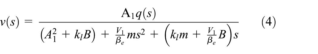
During the plugging process, the hydraulic cylinder piston and its load are considered to be a load on the piston rod for the pressure oil of the rod cylinder of the hydraulic cylinder. Assuming that the pressure in the rod chamber during the sealing process is very low, that is,

The flow equation of hydraulic cylinder is equation (3)

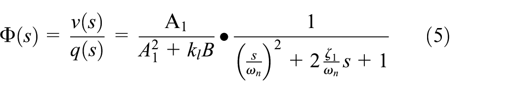
Equations (2) and (3) are transformed to Laplace form to get equations (4) and (5)


Mathematical model of accumulator
In the PIT control system with the energy-saving unit, it is necessary to adjust the parameters of the pressure accumulator exactly, so that the PIT works well. The gas state equation of the accumulator is


Equations (8) and (9) Laplace transform to equation (10)

Mathematical model of relief valve
Relief valve, the most important component in hydraulic system, is widely used in the industrial machinery. Pressure relief valve mathematical model is given as follows

The continuity equation of oil is

Equation (13) is obtained after Laplace transform

Mathematical model of PIT control system
Without considering external interference, the displacement control system block diagram is shown in Figure 5.

The block diagram of pipe isolation tool control system.
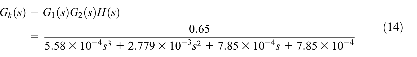
The open-loop transfer function of the system is equation (14)

Control strategy design
The control objectives are velocity-tracking and energy-saving. Three pressure sensors are installed on the pipe to detect the flow field pressure. The control strategy is shown in Figure 6.

The control strategy of pipe isolation tool.
When the PIT has not reached the plugging position around, the pressure of the upstream and downstream is judged. If the pressure of the downstream is higher than upstream, the PIT is decelerated to recover the energy. On the contrary, the PIT accelerates and the accumulator releases energy. When it reaches the plugging position, energy releases. At this point, the pump is the main power source, and the accumulator is an auxiliary power source.
Velocity-tracking control
The aim of the velocity-tracking control is to achieve the PIT execute the target speed accurately. In oil and gas pipeline, with the opening and closing of the PIT, the fluid generates violent fluctuation under the action of inertia, which causes water hammer. Water hammer causes the impact of the flow in the pipeline. The impact can cause some destructive vibration of the pipeline and the PIT. At the same time, the pressure in the pipeline will be several times higher than the normal working pressure and there are serious security threats.26–28 Therefore, on optimizing the plugging speed, the water hammer pressure can be reduced as much as possible within the limited plugging time. And it is controlled within the range of indirect water hammer to ensure the safety of plugging operation.
To ensure the plugging process avoid direct water hammer phenomenon, the plugging time should be greater than the water phase.
29
After optimization, the target plugging speed is obtained as shown in equation (16). The fitting condition is shown in Figure 7. The variance of the two is


Comparison of simulation data and fitted values.
To verify the velocity-tracking control, the energy-saving part of the controller was omitted by setting the proportional relief valve input to a constant value. In this system, due to some parameters are changed during the plugging process, an adaptive fuzzy control method based on fuzzy PID is adopted. The fuzzy controller in this system uses two inputs and three outputs of the structure. Inputs are error E and error rate of change Ec. The output is the three parameters of the PID controller, Kp, Ki, Kd, respectively. By fuzzy reasoning, adjust the PID parameters. The control principle is shown in Figure 8(a).


Fuzzy parameters self-tuning PID control design scheme: (a) Principle of fuzzy PID control, (b) Membership functions curve, and (c) Control surface of PID correction parameters.
Before performing the fuzzy logic calculation, we first confirmed the membership function to be applied to the input and output variables and set the range. The PIT speed error E and speed error rate of change Ec added to the fuzzy controller input. It is converted to fuzzy input linguistic variables by fuzzification. The fuzzy output is deduced according to fuzzy inference rules. The final solution of the fuzzy process is the precise output control Kp, Ki, and Kd. Their values are normalized to values between 0 and 1.
E and Ec are divided into seven fuzzy states, which are NB, NM, NS, ZE, PS, PM, and PB. They represent negative big, negative middle, negative small, zero, positive small, positive middle, and positive big, respectively. The fuzzy domain is [-3 3], and the membership function is a triangle,30,31 as shown in Figure 8(b).
The programming of the rule based in the fuzzy system is complicated and paying attention to each value and order in the regular array is critical. When the range of inputs and outputs has been defined and each set has been named, we could quickly develop or modify the fuzzy controller and reduce the possibility of errors. Based on the name of each variable set, the rules are set up. Among them, Kp adjustment parameters are shown in Figure 8(c). These rules will influence the fuzzy controller to decide by inference engine. When the PID controller was added, the velocity error was 10.28%, and the velocity fluctuated greatly in 64 s. When the fuzzy PID controller is added, the velocity error is 6.65%. Therefore, the fuzzy PID controller could better realize the velocity tracking of the PIT in the process of energy-saving.
Energy-saving control
In order to reduce the energy consumption, the pump pressure would be equal to the pressure required in the actuator. When the PIT is in the unplugging phase, the pressure is compared in the accumulator to determine whether to perform energy recovery. If Pa < Pamax, energy recovery is performed. The flywheel rotates under the influence of the flow field and converts mechanical energy into hydraulic energy, which is stored in the accumulator. If Pa = Pamax, the energy recovery is stopped.
When the PIT is in the plugging phase, the pressure is compared in the accumulator to determine whether to perform energy release. If Pa < Pamin, energy release is performed, the relief valve is open and the extra flow passes through. If Pa = Pamin, energy release is stopped. The relief valve is closed.
In order to verify the influence of the charge pressure of the accumulator on the energy recovery efficiency, the two-way directional valve is closed. The system only provides pressure by the accumulator. By changing the inflation pressure of the accumulator, the effect of different initial pressures on the energy recovery efficiency of the system is obtained.
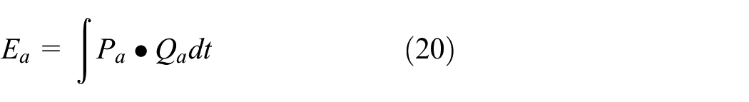
The energy recovery of accumulator is

The energy recovery efficiency is

Experimental results and discussion
In order to evaluate the performance of the proposed control strategy, a series of simulations and experimental tests were performed in Figure 4(c).
The experiment on the plugging velocity is carried out to prove the exactitude of the proposed solution. The optimized plugging velocity curves are simulated dynamically, and the curves of rate of pressure difference change under different plugging velocities are compared, as shown in Figure 9. Where v1 = 0.52 mm/s, v2 = 0.26 mm/s and the optimal velocity is obtained by equation (16). It can be clearly seen that the plugging is carried out under the condition that the plugging velocity is uniform all the time, the rate of change of pressure drop will increase exponentially and far exceed the safety reference value at the end of plugging.

Rate of change of pressure difference at different plugging velocities.
By using the optimal velocity obtained in the experiment to simulate the energy recovery process, the control effect is achieved, as shown in Figures10 –18.

Sinusoidal tracking results without energy-saving unit.

Square wave tracking results without energy-saving unit.

Tracking errors in sinusoidal and square wave test without energy-saving unit.

Tracking results with and without fuzzy proportional integral derivative controller.

Tracking errors with and without fuzzy proportional integral derivative controller.

Pressure signals with and without accumulator.

Flow signals with and without accumulator.
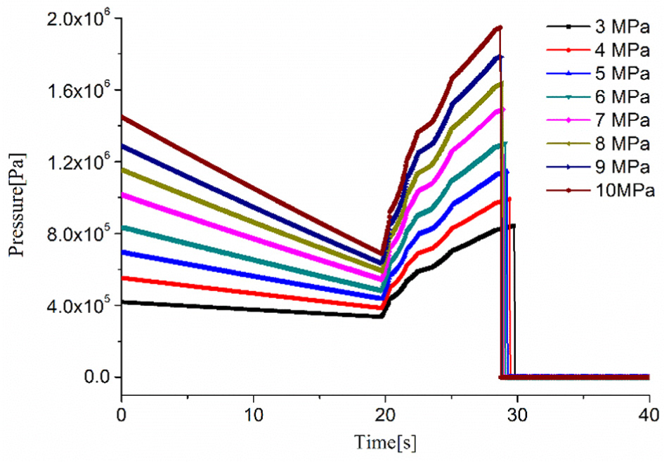
Effect of accumulator pressure on system pressure.

Energy recovery efficiency in different inflation pressure.
Figures 10 and 11 depict the result of the simulations with sinusoidal reference and square wave reference without energy-saving unit. Figure 12 shows the tracking error in sinusoidal and square wave test for the system without energy-saving unit. It is shown in these figures that control algorithm, which is independent of the input signal, has succeeded in realizing velocity tracking.
Then the energy-saving unit is used in the electrohydraulic control system. Figure 13 depicts the result of the simulation with target plugging speed with and without fuzzy PID controller. Figure 14 shows the error in target speed simulation without energy-saving unit. It is visible that, similar to the previous simulations, the energy-saving case has also succeeded in realizing velocity tracking. Figures 14 and 15 depict the pressure and flow signals with and without accumulator for the system. The system can achieve energy recovery by adding accumulator. Figure 17 depicts the effect of accumulator pressure on system pressure. As the accumulator inflation pressure increases, the system pressure becomes larger, but the time becomes shorter. It is shown in these figures that this electrohydraulic control system can achieve energy recovery.
Comparing Figures 10 –12, it can be concluded that the dynamic response of the system has not been charged when the energy-saving unit is active. The tracking error is acceptable in both classic and energy-saving system, which is shown in Figures 12 and 14. Larger errors occur when the speed changes rapidly.
Changing the inflation pressure of the accumulator, the energy recovery efficiency under different pressures was obtained, as shown in Figure 18. In the range of the initial pressure of the accumulator, the efficiency of energy recovery increases as the inflation pressure increases. For example, calculated according to equations (20)–(22), when the accumulator’s inflation pressure is 3 MPa, the kinetic energy consumed by the PIT is 6312.20 J, and the accumulator energy recovery is 368.06 J. So, the energy recovery efficiency is 5.83%. The amount of energy recovery is considerable.
Conclusion
In order to identify the velocity control of plugging process, the PIT structure was simplified. According to the PIT simplified model, a velocity control system with energy-saving is proposed in this article. The optimized velocity was obtained, based on the similarity of Reynolds, which greatly reduced the pressure drop and ensured the safety of the plugging process. Adding a self-tuning fuzzy PID controller to the velocity-control strategy not only improved control accuracy, but also enabled real-time control. Moreover, different input signals had little effect on the results of velocity tracking, so the velocity control strategy could be used for control of target speed. The energy recovery was achieved by an accumulator and a flywheel. Flywheel was used for energy conversion, and the accumulator was used for energy storage. The proposed method was validated through simulation and experiment analysis, and results show that the recovered energy is considerable.
The method was applied to the PIT control system can operate in order and save energy of 5.83%. A new idea was provided for the study of PIT, which could not be operated for a long time due to lack of energy. However, compared to energy recovery studies in other fields, the energy recovery efficiency of PIT is still low. Future work will focus on reducing leakage and temperature changes to improve energy recovery efficiency. In addition, the recycling rate of recovery energy is increased by reducing the mismatch between installed and demanded power.
Footnotes
Appendix
Notation

| P1 | – | (Pa) | Rod cavity pressure of hydraulic cylinder |
| A1 | 7.85 × 10⁻⁴ | (m2) | Rod cavity area of hydraulic cylinder |
| P2 | – | (Pa) | Rodless cavity pressure of hydraulic cylinder |
| A2 | 15.7 × 10⁻⁴ | (m2) | Rodless cavity area of hydraulic cylinder |
| m | 400 | (kg) | Hydraulic cylinder equivalent mass |
| vs | – | (m/s) | Hydraulic cylinder velocity |
| B | 0.8 | (N s/m) | Piston viscous damping coefficient |
| Qc | – | (m3/s) | Flow of cylinder |
| kl | 3 × 10⁻¹⁵ | (m3/(Pa s)) | Hydraulic cylinder leakage coefficient |
| V1 | 3.4 × 10⁻⁵ | (m3) | Rod cavity volume of hydraulic cylinder |
| 7 × 10⁸ | (Pa) | Hydraulic fluid bulk modulus | |
| Pa0 | – | (MPa) | Pressure of accumulator at certain working point |
| Va0 | – | (m3) | Volume of accumulator at certain working point |
| Pa | – | (MPa) | Pressure of accumulator at any working point |
| Va | – | (m3) | Volume of accumulator at any working point |
| k | 1.4 | (–) | Polytropic index |
| Aa | – | (m2) | Cross-sectional area of accumulator chamber |
| Qrv | – | (m3/s) | Flow of relief valve |
| KQ | – | (m2/s) | Flow gain of relief valve |
| xv | – | (m) | Opening degree of relief valve |
| KC | – | (m3/Pa s) | Flow pressure coefficient of relief valve |
| Prv | 8 | (MPa) | Setting pressure of relief valve |
| vi | – | (m/s) | Plugging velocity input |
| v0 | – | (m/s) | Plugging velocity output |
| Ka | – | (–) | Amplifier gain |
| Kv | – | (-) | Valve flow gain |
| Tv | 0.2 | (–) | Time constant |
| Kf | – | (–) | Sensor coefficient |
| FL | 0 | (N) | External interference force |
| PU | – | (Pa) | Upstream pressure |
| PD | – | (Pa) | Downstream pressure |
| t | – | (s) | Plugging time |
| v | – | (mm/s) | Velocity of plugging |
| Pamax | – | (MPa) | Maximum pressure of accumulator |
| Pamin | – | (MPa) | Minimum pressure of accumulator |
| Ea | – | (J) | Energy of accumulator |
| Qa | – | (m3/s) | Flow of accumulator |
| Esg | – | (J) | Energy of speed governor |
| msg | – | (kg) | Quality of speed governor |
| vsg | – | (m/s) | Velocity of speed governor |
| v1 | 0.52 | (mm/s) | One of the plugging velocities |
| v2 | 0.26 | (mm/s) | One of the plugging velocities |
Handling Editor: Hongfang Lu
Declaration of conflicting interests
The author(s) declared no potential conflicts of interest with respect to the research, authorship, and/or publication of this article.
Funding
The author(s) disclosed receipt of the following financial support for the research, authorship, and/or publication of this article: This work was financially supported by the National Natural Science Foundation of China (Grant 51575528).