
Abstract
The lack of sensory feedback provided by prosthetic hands dramatically limits the utility of the device. Peripheral nerve interfaces are now able to produce stable somatosensory percepts for upper limb amputees. Sensors must be able to detect forces across the fingers of the prosthesis in a repeatable and reliable fashion. We solved this concern with a novel multi-modal tactile sensor which consists of an infrared proximity sensor and a barometric pressure sensor embedded in an elastomer layer with potential use in prosthetic devices. Signals from both sensors measure proximity (0–10 mm), contact (0 N), and force (0–50 N) and are combined to localize impact at five spatial locations and three angles of incidence. Here, we describe the sensor design, its characterization, and data analysis. We use Gaussian process regression to fuse the signals from both sensors to obtain calibrated force in Newton with an R2 value of 0.99. We use supervised learning to localize probe position and direction with classification accuracies of 96% and 89%, respectively. The complementary nature of both sensors leads to several sensing modalities that no one sensor can provide on its own and the repeatable, reliable, and compact form of the sensor enables use in multi-functional prosthetic hands.
Keywords
Introduction
The field of upper limb prosthetic design has made great progress toward recreating what was lost after amputation. Multi-functional prosthetic hands include up to six independent actuators, can produce closing speeds of less than 1 s, and forces as high as 100 N that enable everyday use 1 (Figure 1). Now, advanced feedforward control algorithms which enable more intuitive use of the prosthesis are becoming clinically relevant through many commercial partners.2–4 These myoelectric control algorithms provide improved control of the multi-functional prosthesis over the standard direct control techniques used previously. 3 Now, the largest deficiency in our field is the lack of feedback systems to provide sensory restoration for the user.5,6 A sensory restoration system must include both sensors which monitor the position and forces on the prostheses as well as a biological interface to the intact neural system.
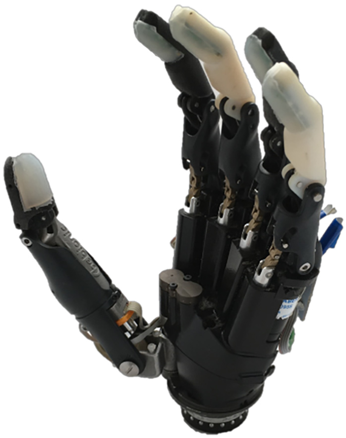
Modified Bebionic hand (RSL Steeper, Inc.) with multi-modal PCF tactile sensors at each finger.
Current prosthetic hands are essentially numb; the user is not directly aware of the tactile interactions between the hand and the environment. However, it is well known that somatosensory information is essential for effective grasping and manipulation. 7 The most critical element in order to provide sensory restoration for upper limb amputees is a stable and precise neural interface which provides physiologically appropriate sensory feedback. The most promising sensory restoration techniques today use the peripheral nervous system as the portal to the afferent pathways. In the peripheral nervous system, nerve fibers are organized in a somatotopic manner such that the nerve fascicles which innervate specific areas of the hand form distinct clusters in the nerve. 8 This organization allows empirical mapping of electrode sites in a peripheral nerve implant to specific skin areas in the hand. Several technologies in this area have progressed dramatically in recent years to the point that human trials took place.9–13
Raspopovic et al. 9 demonstrated a transversal multichannel intrafascicular electrode as a method to distinguish three distinct force levels in a single upper limb amputee. However, long-term use was not demonstrated in this study but is certainly a critical element of any neural interface. The Utah Slant Electrode Array is a well-established device for recording and stimulating from the peripheral nervous system. 12 Recently, the Utah Slant Electrode Arrays were first implanted in two upper limb amputees for a 30-day time period. These implants were able to elicit over 80 sensory percepts (as well as feedforward control of a virtual robotic hand). 13
The most mature peripheral neural interface is the flat interface nerve electrode (FINE).10,14 This system allowed subjects to discriminate and match intensity of sensation and recognize changes in magnitude of the stimulation. 11 Also, subjects were shown to experience improved object discrimination, object manipulation, and embodiment when provided sensory restoration. 15 However, these remarkable results were produced with simple fingertip sensors: force-sensitive resistors (Tekscan FlexiForce A201) which only measured loads normal to the surface of the sensor between the loads of 0 and 4 N. A sensor with richer information and the ability to detect loads away from the center of the sensor could benefit the field of upper limb prosthetic design.
Most research and commercially available prosthetic hands lack sensors which can provide feedback required for effective grasping and manipulation. The measurement of the position of the digits in the hand (proprioception) and the forces applied to the digits (tactile) is a necessary component of any closed-loop prosthetic limb system.
Numerous tactile sensors have been designed in both the robotics16–18 and the prosthetics literature.19,20 Balek and Kelley 21 provide one of the earliest applications of proximity sensors for control of a robot arm. More recent studies demonstrate the use of proximity information for pre-grasp alignment and reactive grasping,22,23 for point-cloud construction of objects 24 and slip detection, 25 and for learning a sequential manipulation task. 26 However, many barriers remain for these sensors to be integrated into self-contained prosthetic hands including the digital communication systems, the multiplexing of multiple sensors, and the wiring of the sensors throughout the device. In particular, none of these proximity sensors can classify spatial position and angular orientation of forces, which ensures that sensory restoration can take place reliably and repeatedly even when the external forces are not centered and/or to the fingertip surface.10,11 During grasping tasks, the digits conform around objects using a variety of grasp postures. 27 The forces applied to the fingertips during those grasps can vary in both spatial location and angular orientation with respect to the fingertip surface. A reliable tactile sensor must be able to detect these off-centered and non-normal loads in order to provide relevant sensory information back to the user.
This article presents a new prosthetic fingertip sensor which integrates an infrared (IR) emitter-detector and barometer to form a proximity, contact, and force (PCF) sensor (Figures 1 and 3). The technology presented here is a combination of work previously presented by Patel and Correll 18 and Tenzer et al. 28 Here, similar integrated chip sensors were integrated into a prosthetic finger and overmolded with an elastomer to create a robust contact surface for the prostheses. Standard I2C communication between sensors and prosthetic hand controller ensures stable and reliable communication. This multi-modal sensory information provides rich data to perform sensory fusion to derive additional information not available from each sensor independently. The resulting multi-modal fingertip sensors provide proximity sensing, zero-force contact sensing, linear force readings from 0 to 50 N, and the ability to classify five spatial locations and three angles of incidence in a repeatable, reliable, and compact fingertip sensor.
Methods
PCF sensor design
The PCF sensor presented here is a combination of two IC sensors: a microelectromechanical system (MEMS)-based barometric pressure sensor (MS5637-02BA03) and an IR proximity sensor (VCNL4010). Thanks to the recent availability of electromechanically dense sensors which include auxiliary circuitry like instrumentation amplifiers, analog-to-digital converters, and standard bus interfaces into small packages, we were able to integrate these sensors into a durable, self-contained system. The assembly of the PCF sensor consists of several steps. We arranged the sensors (IR proximity and barometer sensor) on a custom printed circuit board (PCB) along the mid-line of the fingertip. We modeled the original fingers of the Bebionic v2 hand (RSL Steeper) and added a cavity for the PCF sensor (Figure 1). We also created a mold for the elastomer as described below. The fingertip bodies were prototyped using standard three-dimensional (3D) printing techniques. A liquid silicon polymer (Dragon skin 10) was poured into the mold with the fingertip sensor. This elastomer was chosen due to its low viscosity when pouring into molds and mechanical robustness post curing. A vacuum was applied 28 before pouring the liquid silicon into the mold to completely remove air from the polymer.
We designed an additional PCB to multiplex the sensor’s I2C signals for access by a host computer (two signals per finger, 10 signals in total) via an Arduino microcontroller. The Arduino firmware performs the proximity calculation for the IR sensor as well as the calibration and temperature compensation for the barometer (using algorithms provided by the sensor manufacturer). The firmware then sends the calibrated proximity and pressure data to the laptop computer through a serial USB interface. A custom LabVIEW (National Instruments Inc.) program is used to visualize the real-time signals and store the data for off-line processing and analysis.
Multi-modal signals
The multiple sensing modalities of the sensor are depicted in Figure 2. In order to highlight the various modalities of the sensor, a small piece of cotton is dropped from a fixed height onto the sensor. We choose cotton because of its light weight and to show that the IR sensor can detect contact forces close to 0 N that the barometer sensor is unable to measure. The contact detection is clearly visible as a small peak in the green curve. The cotton is then gently pressed against the sensor. This change in the force is picked up by the barometer in a (nearly) linear manner. Notice that the barometer signal shows no noticeable change when the contact event is detected by the IR sensor. The proximity signal includes some non-linear elements which are visible in the curve at the time force is applied on the cotton. The contact signal is derived by passing the raw IR signal through a first-order Butterworth high-pass filter. The barometer provides a proportional measurement of the pressure within the fingertip sensor which is stable across all loads (tested up to 50 N).

Multi-modal sensor response when a small piece of cotton is dropped onto the sensor and pressed.
Experimental characterization
To experimentally characterize the performance of the sensors, multiple fingertip sensors were fabricated and tested. An Instron material testing machine (MTS Insight II—low capacity: 2 kN maximum) applied calibrated loads at various spatial positions and angles of incidence on the fingertip as detailed below. The loads were applied using a probe with a flat circular tip (15 mm diameter) and monitored using a 250 N load cell (model: M569326-06). The MTS machine applied prescribed loads ranging from 1 to 50 N at a rate of 1 mm/s with a sampling rate of 16 Hz. Additional fingertip “pillows” were prototyped in order to locate the fingertip sensor in the prescribed spatial and angular orientations with respect to the probe. The spatial dataset measured contact events at the center, 2.5 mm distally, 2.5 mm proximally, 2.5 mm medially, and 2.5 mm laterally and the angular orientation dataset measured contact events at the angles of 0, 20, and −20 degrees (Figure 3). These spatial and angular conditions were chosen in order to span the entire range of the detectable volume of the fingertip sensor. The center location was defined as directly above the midpoint of the PCB. The angular orientations were defined with respect to the normal vector of the PCB. In each condition, a sequence of 10 contact events at each maximum load took place. Each contact event was separated by a 1-s delay. The maximum loads tested were 1, 5, 30, and 50 N. These loads were chosen to span a typical range of loads seen by prosthetic fingers in everyday use.

Tested locations of spatial positions (left) and angular orientations (right) on the PCF sensor. These positions and angles span the range of the fingertip sensors.
The sensor fusion study followed the following procedure: We fixed the direction of probing angle to 0 degrees to obtain the mapping from the analog proximity and pressure readings to true force in Newton. We perform 10 dynamic loading and unloading cycles on the finger using the same Instron machine described above. Hoping to generalize these loading and unloading cycles to everyday forces that the sensor would experience, we perform this test with multiple maximum load forces (1, 5, and 50 N). Note that the finger and the probing location are kept constant for this calibration. In total, we have 10 curves for each maximum load force from the barometer sensor, IR sensor, and the load cell for a total of 90 curves (10 × 3 × 3).
To collect data for classifying the direction of probing, we perform 10 dynamic loading and unloading cycles with the Instron machine for the maximum peak forces of 1, 5, 30, and 50 N at 0, 20, and −20 degrees of probing direction. We use custom-made 3D-printed pillows for the finger that align it at various angles with respect to the probe. In total, we have 120 combined loading and unloading curves.
To determine the spatial location of impact on the finger, the data were collected by probing the finger at different locations with respect to the center of the finger (Figure 3). We again make use of custom-made 3D-printed pillows to align/offset the finger with respect to the center of the probe. Our data collection procedure consists of 10 dynamic trials of loading and unloading for each of the maximum forces of 1, 5, 30, and 50 N for five spatial locations with respect to the barometer. The data are segmented into a single combination of loading and unloading curves summing to a total of 200 curves (10 × 4 × 5).
Data analysis
The calibration of multi-modal analog data to actual force is non-trivial. The combined signals from the fingertip vary based on the position and orientation of contact. Therefore, it is challenging to estimate a single function with a fixed number of parameters that will map the raw barometer and IR readings to true force. In result, we relied on Gaussian process (GP) regression.
The GP approach is a non-parametric approach in that it finds a distribution over the possible functionsf (x) that are consistent with the observed data. In a regression setting, we aim at finding the functiony=f (x)+E with y being the observations, x a set of independent variables, and E being an error term. A GP is defined by a mean function m(x) and covariance function k(x, xt), otherwise known as the kernel function. GP defines a prior over the possible functions, which can be converted to posterior once data are available. In other words, we have some known parameters x for which we have some observed outcome f (x). Suppose that there are some points x* for which we would like to estimate f(x*).
We estimate the conditional probability p(f*|x, x*, f) on the assumption that the functions f and f* are drawn from a joint distribution defined by the GP. A specific advantage of GPs in our case is that they are computationally affordable on small datasets and have a well-tuned smoothing property.
We frame the problem of localizing external loads on the finger into two separate supervised learning problems: (1) classification of the spatial location of load and (2) classification of the angle of incidence of the force at the angles of 0, 20, and −20 degrees (Figure 3). The organization of the machine learning methods here was used as a proof of concept for a more sophisticated algorithm that could classify both spatial and angular orientation in real time.
Support vector machine (SVM), k-nearest neighbor (kNN), dynamic time warping (DTW), naive Bayes, and so on are very popular due to their high computational efficiency and high resistance to noise.29–31 However, it is inherently difficult to design good features that can capture intrinsic properties embedded in various time series data. Several deep learning frameworks are better in such cases as they do not need any handcrafted features by people, instead they can learn a hierarchical feature representation from raw data automatically.32–34 To compare these two supervised learning frameworks, we train an SVM classifier and a convolutional neural network (CNN) for each of the supervised learning problems.
Results
The PCF sensors were characterized and shown to be able to detect five spatial locations and three angles of incidence. The PCF sensor utilized both the IR and barometer signals in order to produce a more repeatable, reliable, and compact sensor design. IR proximity sensor signals are heavily dependent on the object surface reflectivity. This makes it challenging to calibrate the sensor. Using the barometric sensor signal, we are able to fuse the IR proximity with the barometric sensor signal to measure calibrated forces independent of the position/angle of contact. The responses of the barometer and IR proximity sensor to the applied force at any spatial location on the finger are also distinctively different. Figure 4 shows the response of both sensors at 30 N load and 0 degree probing angle for all spatial conditions (images placed in the form of a “+” sign). Figure 4 also shows the response of both sensors at 30 N load across all angles of incidence (bottom right/left images). The barometer shows a linear behavior to applied force after its minimum range has been crossed, whereas the IR sensor shows a non-linear behavior while being sensitive in a range below that of the barometer. Their behavior is repeatable over a fixed location (each curve is an average of 10 contact events) on the finger over multiple days, but varies in an irregular manner across those positions on the finger. These variations are more dramatic for the IR sensor compared to the barometer sensor. These repeatable, yet irregular signals across spatial position and angular orientation allow us to localize force on the sensor’s surface.

PCF sensor readings as a result of multiple contact and lift events at five spatial locations and three angles of incidence. Each curve is an average of 10 contact events (with shaded bar as the standard deviation).
Sensor fusion
The raw signal data are preprocessed through a low-pass filter to remove unwanted noise. To segment out an individual curve consisting of loading and unloading cycles at a particular maximum peak load force, we first locate the peaks from each contact. After locating the peaks, we take a window of 180 samples (90 samples on each side of the peak) and segment out the individual loading and unloading curves. We then concatenate individual peaks from each sensor at the peak load forces of 1, 5, and 50 N into a single array. This gives us a 3 × 10 set of data: 3 sensors (two on the finger and the external force sensor) and 10 measured contact events.
We trained the kernel of the GP by providing it a set of inputs xTrain and targets yTrain. Inputs correspond to concatenated raw IR and barometer values, and targets correspond to forces in Newton from the external load cell. We then normalize all the values. The Gaussian kernel that we are using is a radial basis function (RBF) kernel (also known as squared exponential kernel) implemented in the scikit-learn library. After the kernel has learned the relationships within the data (xTrain and yTrain), we present it with the testing dataset to predict the labels yPred given the xTest. The accuracy of the fit is determined using the root mean square error (RMSE) and R2 score. Figure 5 shows the individual curve fit for the barometer and IR readings (before concatenating them) and the fit in 3D after concatenating them and learning the kernel. Note that the kernel parameters are the same for all three fits and are experimentally calculated to have minimal error in the 3D plot. The RMSEs and R2 scores of the three fits are shown in Table 1.

Gaussian process regression fit for (a) barometer sensor values, (b) infrared sensor values, and (c) combined, to force in Newton (the barometer and infrared sensor values are normalized). Measures of the fits are listed in Table 1.
Root mean square and R2 error measure for curve fitting (Figure 5).

IR: infrared; RMSE: root mean square.
Force localization
The interaction between the elastomer mold and the sensors itself is difficult to model due to the non-linear nature of the geometry and loading conditions. This interaction leads to proximity and pressure signals of varying nature from the sensor when it is impacted from different directions and at different locations. To localize impact on such a dynamic sensor, we break down the problem into two smaller subproblems. First, we identify the angular direction of probing and second the spatial location of impact with respect to the center of the fingertip. We frame this as a classification problem in supervised learning framework and train an SVM and a CNN for each of the subproblems.
Probing direction
The raw data are arranged for post-processing and then we locate the peaks from a single loading and unloading curve of every data collection trial. After locating the peaks, we take a window size of 150 samples (75 samples on each side of the peak) and segment out the individual loading and unloading curves. We then standardize the individual loading and unloading curves to have zero mean and one variance.
We use SVM as a baseline classifier since the amount of data collected for classification is small. An advantage of such a model is that fewer parameters are needed to be learned and the user has greater control over the model itself. We extracted several parameters from the barometer and IR sensor signals to create features for the SVM. The most promising feature was the ratio of the IR and barometer values which gave us a significant rise in testing accuracy.
We also included the data points of maximum force and minimum force from the sensor into our feature vector. We used a polynomial kernel with a penalty factor of C = 1. In order to avoid overfitting of our models to the data, we perform cross validation on all of the models described below. The accuracy obtained after sixfold cross validation is shown in Table 2. In addition, we trained a small neural network to classify the probing direction. Since convolution inherently captures the relation between the signals it is convolving across, we did not have to hand engineer the features ourselves. We feed the raw data directly into the network. The network consists of two 2D convolution layers followed by a flattened layer and finally a dense output layer of 3 neurons with softmax activation. The accuracy obtained after sixfold cross validation on the training and testing datasets is shown in Table 2.
Accuracies for probing angle classification.

SVM: support vector machine; CNN: convolutional neural network.
Spatial location
The features extracted for training the SVM were similar to those described previously. An RBF kernel with a penalty factor of C = 8 was experimentally found to give a mean classification accuracy of 0.959 (±0.0354) after sixfold cross validation (Table 3).
Accuracies for spatial location classification.

SVM: support vector machine; CNN: convolutional neural network.
The neural network architecture is also the same as described previously, except for an increase in the number of output neurons on the dense layer from 3 to 5, as we now have five labels to classify. The number of filters, their size, and kernel parameters were kept constant to compare the results. The accuracy obtained after sixfold cross validation on the training and testing datasets is shown in Table 3.
Discussion
We believe that the sensor presented here has a large variety of potential applications in prosthetic and robotic grasping due to its ability to estimate proximity, contact, force, location, and direction of impact.
This work was motivated by the need in the field of prosthetic limb design for better fingertip sensors in prosthetic hands. The advancements in the field of robotics can provide great value if designed properly for prosthetic hand use. These multi-modal fingertips provide supplemental information compared to standard tactile sensors which only provide force measurements. The proximity sensing can be useful in grasp planning and other shared control methods of prosthetic hands. 35 In these semi-autonomous feedforward control methods, the user commands a specific desired grasp and then the prosthesis can adapt that command based on the feedback from peripheral sensors. The proximity sensory presented here would enable this type of control in a myoelectric prosthetic hand. The utility of the proximity data for sensory restoration is not yet known. Of course, the physiology of human fingers cannot detect proximity to nearby objects so this measurement does not have a physiologically appropriate mapping. However, novel mappings between the proximity signal and other tactile percepts are now possible using the technology presented here.
The GP method enabled us to fuse the barometer and IR sensor values to form a calibrated force signal. For the classification task, SVM outperforms the CNN approach, which we believe to be due to overfitting.
Although the numerical values are a good fit, the proposed methods might not necessarily generalize over different probing shapes and material since the shape of indentation on the elastomer drives the signals in an unpredictable manner. Even though GP regression is the most accurate regression method, it has an exceptionally high computational complexity which prevents its usage for large numbers of samples or learning online. The IR proximity sensor has a strong dependence on the surface properties (i.e. color and reflectivity) of an object which can throw off the calibration for objects. However, we believe that the sensor’s multiple sensing modalities will help mitigate some of the challenges discussed above. The linear behavior of the barometer could help calibrate the sensor against objects with a variety of surface properties. The non-linear response of the IR sensor could be used to identify those surface properties.
At the very least, our sensor’s extended spatial capabilities will provide relevant force feedback to amputees even when an object is not centered against each digit. This fact will provide a better sensor for the advanced neural interfaces since we can ensure a reliable source of force feedback during the complex activities of daily life. This is possible due to the effectiveness of these two distinct signals: (1) the reflectance of IR light off a reflecting surface and (2) the change in pressure due to the compression of an elastomer. Here we show that in combination these signals can be utilized to create an even richer picture of the interactions between the outside world and the fingertips of a prosthetic hand.
Conclusion
In this work, we describe the utility of a multi-modal prosthetic fingertip sensor which consists of an IR proximity sensor and a barometer embedded in an elastic polymer. The compact sensors include all of the instrumentation, analog-to-digital conversion, and control circuitry which ensure reliable signal quality using the standard I2C communication protocol. The molded elastomer fingertip surface provides a durable interface to manipulate objects while allowing reliable measurements of those interactions. We characterized the fingertip sensor over loads varying between 1 and 50 N, and measured the system’s response to loads applied spatially about the center and angled with respect to the normal surface of the fingertip. This characterization encompassed 28 distinct loading scenarios. We designed a GP model to fuse the raw barometer and IR sensor readings to determine the applied force with an R2 value of 0.99. Then, we identified the location of loading using supervised learning methods and obtained the classification accuracies of 96% and 92% using SVM and CNN, respectively. We similarly classified the probing angle and obtained the classification accuracies of 89% and 83%, respectively.
In the future, our development will focus on the integration of these sensors with neural interfaces in order to provide rich sensory information to upper limb amputees. The calibrated force signal will provide a reliable tactile signal, while the proximity and contact signals allow for investigations of new sensory paradigms. The proximity signal can be mapped to non-physiological percepts, while the contact signal can be utilized in a DESC-based manner. Furthermore, we plan to implement real-time sensor fusion classification. Once accomplished, the spatial and angular information may be relevant to certain neural interfaces and/or may be used in shared control paradigms of the prosthetic limb. The multi-modal fingertip sensors assist the field of upper limb prosthetic design to provide rich sensory information back to upper limb amputees.
Footnotes
Handling Editor: Long Cheng
Declaration of conflicting interests
The author(s) declared no potential conflicts of interest with respect to the research, authorship, and/or publication of this article.
Funding
The author(s) disclosed receipt of the following financial support for the research, authorship, and/or publication of this article: This work was supported by the Career Development Award Number IK1RX00201 from the United States (U.S.) Department of Veterans Affairs Rehabilitation Research and Development Service, the Airforce Office of Scientific Research, and the Colorado Advanced Industry Accelerator Grant.