
Abstract
The drum driving system is the weakest part of a drum shearer, and most of the previous dynamic analyses neglect the housing flexibility. Therefore, some efforts are needed to refine the dynamic model and sufficiently understand the dynamic behavior of the drum driving system. Establishing a system-level model of the drum driving system is challenging because the drum driving system consists of many components such as the cantilever loaded housing, multistage gear transmission, electric motor, and drum. In this study, an improved three-dimensional gear model with the time-varying pressure angle and contact ratio due to center distance variation is proposed. Then, a standard coupling method is proposed to construct the hybrid dynamic model of the drum driving system automatically. Finally, a comparative analysis of the dynamic responses of the drum driving system under two loading scenarios (i.e. applying only the cutting moment and applying both the cutting moment and cutting force) revealed that the three-directional cutting force was the primary external factor that leads to the housing deformation. And some principles for designing the drum driving system under such a large deformation condition are also identified.
Introduction
The drum shearer is a key equipment in the long-wall mining system, which has been the dominant coal mining method for decades in the world. The stable and reliable operation of the drum shearer is highly critical to safe and efficient production on a completely mechanized coal mining face. 1 The drum driving system is the pivotal component for realizing coal cutting and consumes 80%–90% of the total power used by the shearer. 2 Figure 2 shows a typical schematic of the drum driving system of a shearer, which consists of an asynchronous motor, a gearing system, a drum, and a ranging arm housing. According to the recent statistics, 3 the drum driving system is the most vulnerable component of the shearer. As illustrated in Figure 1, the ranging arm housing is cantilevered and prone to result in a large deformation by the fluctuant drum load. Housing’s large deformation will make the dynamic characteristics of the transmission system different from the ideal state. Therefore, the impacts of a large housing deformation on the dynamic characteristics of the transmission system should be taken into consideration at an early design stage, and some principles for designing the drum driving system with a large housing deformation should be proposed.

Drum shearer and its working principle: (a) photograph of the actual drum shearer and (b) schematic illustrating the working principle.
As an electromechanical system with multistage gears, the systematic dynamic response of the shearer’s drum driving system has received considerable attention from researchers and engineers. Dolipski et al.4–6 described a lumped-parameter dynamic model of a shearer’s cutting system and verified it through experimental tests, and the interactions of coal hardness and hauling speed on gear meshing force were also analyzed. Jiang et al. 7 established a nonlinear gear dynamic model of the drum driving system with multi-frequency excitation load and developed a useful indicator based on maximal Lyapunov exponent to identify the gear crack degrees. Liu et al. 8 proposed an electromechanical dynamic model including the electric motor and the electromechanical dynamic characteristics of the drum driving system were simulated during the speed change process. Ge et al. 9 established a torsional electromechanical coupling model of a drum driving system and investigated the control strategy for suppressing the dynamic load of the gear transmission system under impact load. However, the coupling effects of the ranging arm housing deformation and the transmission system were neglected in the above-mentioned studies. Previous studies show that the nucleus of the gear system dynamic model is the modeling of gear tooth contact actions. 10 , 11 Since housing deformation will indeed change the instant screw axes of a pair of gears and then change the tooth contact action,12–14 the housing flexibility should be included in the prediction process of dynamic responses. Through the virtual prototyping of a drum driving system using the ADAMS software, Zhao and Ma 15 calibrated the stress of the ranging arm housing and deformation of the planet carrier. However, because of the simplified gear dynamic model, this study did not consider the effects of the deformation of ranging arm housing on the engaging state of the gears. Zhao and Lan 16 modeled one pair of gears through finite element method in their virtual prototype of a ranging arm to solve contact problems and obtained the contact stress on the tooth flanks under a steady cutting load. However, this model focused only on one pair of gears among a large number of gears and failed to investigate the overall dynamic characteristics of the complete drum driving system under the ranging arm housing deformation conditions. Qin and Jia 17 established a dynamic model of the complete drum driving system using the hybrid dynamic substructure method that combined the finite element model of housing and the lumped-parameter model of the transmission system. Their model was validated qualitatively through experiments, and then the dynamic meshing force and dynamic equivalent mesh misalignment under housing deformation were calculated through computer simulation. However, the gear dynamic model that Qin and Jia 17 used to compose the drum driving system was not close enough to reality, since it neglected the fluctuation of pressure angle and contact ratio due to the gear center distance variation under housing deformation conditions. Recent research18–20 indicated that the variation of gear center distance will change the pressure angle and contact ratio, which observably influence the gear dynamic responses. So the pressure angle and contact ratio should be regarded as the time-varying variables in the hybrid dynamic model of the drum driving system. Since these studies18–20 restricted the motion of the gears within a two-dimensional (2D) plane, a new three-dimensional (3D) parallel-axis gear model should be proposed considering the time-varying pressure angle and contact ratio.
In this study, considering the gear center distance variation, a 3D parallel-axis gear model with time-varying pressure angle and contact ratio is proposed for the first time, which can be viewed as a generalization of the previous studies.18–20 Then, the gear dynamic model in the authors’ previous work 17 is replaced by the newly proposed more realistic one, and other subcomponent models are inherited directly, that is, housing model, planetary gear model, gear shaft model, asynchronous motor model, and random drum load model. So a better theoretical accuracy of the hybrid dynamic model can be expected. In addition, a standard and automatic coupling method using matrix calculation is proposed to replace the previous manual matrix transformations. 17 That means the proposed coupling method can improve the speed of modeling and reduce the possibility of error at the same time. A comparative analysis of the dynamic characteristics of the drum driving system under two loading scenarios, that is, M (applying only the cutting moment) and M + F (applying both cutting moment and cutting force), showed that the three-directional cutting force was the primary external factor leading to the large deformation of the ranging arm housing. Then, the impacts of this large deformation on the dynamic characteristics of the key components of the transmission system (such as gears, bearings, and flexible shaft) were examined. The analysis results could provide guidance in the design and simulation of a drum driving system under a large housing deformation condition.
Shearer and drum driving system
Figure 1(a) illustrates an actual drum shearer. The guide rail supports and guides the shearer body. The hydraulic cylinder regulates the angle of the ranging arm, which allows the drum to follow the height of the coal seam. The cutting picks around the periphery of a drum produce the coal cutting action when the drum rotates. During operation, the shearer advances at a certain hauling speed on the guide rail, while the front (upper) and rear (lower) drums operate in a coordinated manner, which makes it possible to cut the entire height of the mine face in one run. Figure 2 shows a schematic of the drum driving system of a 1.2 MW shearer, which consists of an asynchronous motor, a gearing system, a drum, and a ranging arm housing. The gearing system includes two-stage parallel-axis gears (Z11–Z13 and Z21–Z26) and two-stage planetary gears. The ranging arm housing is manufactured using ZG25Mn2 through integral casting, with a Young modulus of 202 GPa and a Poisson ratio of 0.3.
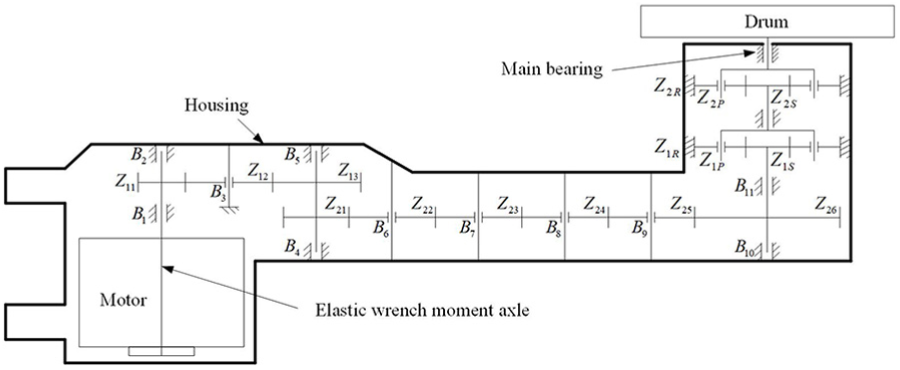
Schematic of the drum driving system of a 1.2 MW shearer.
Dynamic modeling of the drum driving system
An improved 3D gear dynamic model
In this study, the classical gear dynamic model, the pseudo-3D thin-slice approach
21
is improved by regarding pressure angle and contact ratio as the time-varying variables. The pinion and gear are assimilated to two rigid cylinders with 6 degrees of freedom (DOFs) each, and the generalized displacements of gear

where

Parallel-axis gear model.
As illustrated in Figure 3, the gear center is denoted as


where
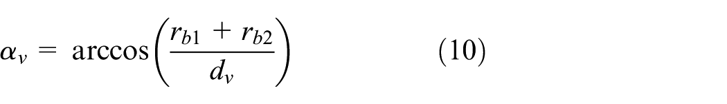
The core of equations (2) and (3) is calculating
The generalized displacements of infinitesimal gear center


where
Following del Rincon et al., 20 the normal deviation and its derivative of the infinitesimal mesh element are expressed as follows
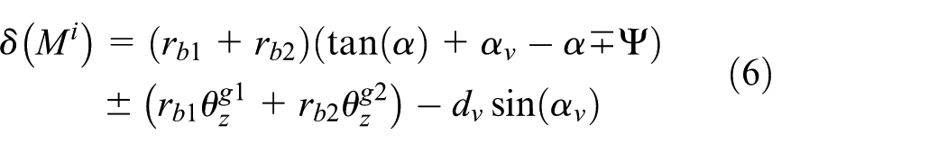
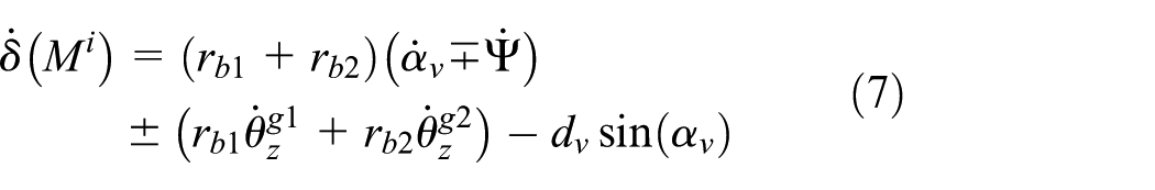
where


where

The model of infinitesimal mesh element (a) at ideal position and (b) with nonstandard center distance.
Subcomponent dynamic model in the matrix form
The dynamic models of ranging arm housing, gear shafts, planetary gears, asynchronous motor, and drum load have been established by the authors in their previous work, 17 which will be used directly in this work. These subcomponent models and the parallel-axis gear model proposed in the above section will be expressed in the unified matrix terms. The benefit is that researchers and engineers can couple different subcomponent models together automatically through matrix calculations, especially when the transmission system consists of many subcomponents

where the superscripts denote different subcomponents: ranging arm housing
A standard coupling method
As illustrated in Figure 5, the drum driving system consists of the ranging arm housing, parallel-axis gears, planetary gears, gear shafts, asynchronous motor, and the drum. These subcomponents are connected through three kinds of connections: linear flexible connection, nonlinear flexible connection, and rigid connection. Since the dynamic models of subcomponents are established under the unified coordinate, no coordinate transformation is needed when coupling them together. Therefore, only two steps are needed to construct the coupling dynamic model of the drum driving system:
Step 1. Stack the subcomponent models up directly in the form of block diagonal matrix

where
As shown in Figure 5, the node numbers of boundary points on the housing range from 1 to 17, the node numbers of parallel-axis gears are from 18 to 26, the node numbers of planetary gears are from 27 to 37, the node numbers of gear shafts are from 38 to 77, the node number of motor is 78, and the node number of drum is 79. At this step, there are 79 nodes in total.
Step 2. Obtain the coupling dynamic model through matrix calculation
Equation (13) has not considered the three kinds of connections illustrated in Figure 5. This step demonstrates how to make the independent subcomponent models coupled through matrix calculation. Since two rigid-connected nodes have identical displacement, speed, and acceleration, they can be viewed as a single node. As shown in Figure 5, 14 nodes can be eliminated by 14 rigid connections. Therefore, the coupling drum driving system has 65 nodes in total finally. The matrix calculations for the three kinds of connections are demonstrated as follows:
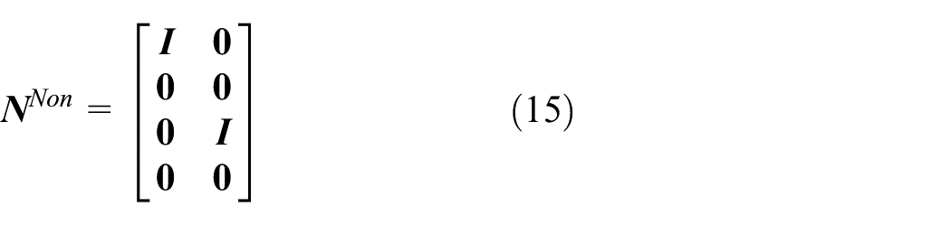
Matrix calculation for nonlinear flexible connection
After adding nonlinear flexible connections to these subcomponent models, equation (13) can be rewritten as follows

Without loss of generality, take such a system as an example: four nodes in total, node 1 and node 3 are coupled through nonlinear flexible connection. The calculation of
Define
Therefore

where
If the number of nonlinear flexible connections is greater than one, add these connections one by one

When the nonlinear function and node numbers of the two connected nodes are known, the vector
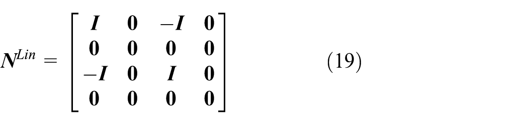
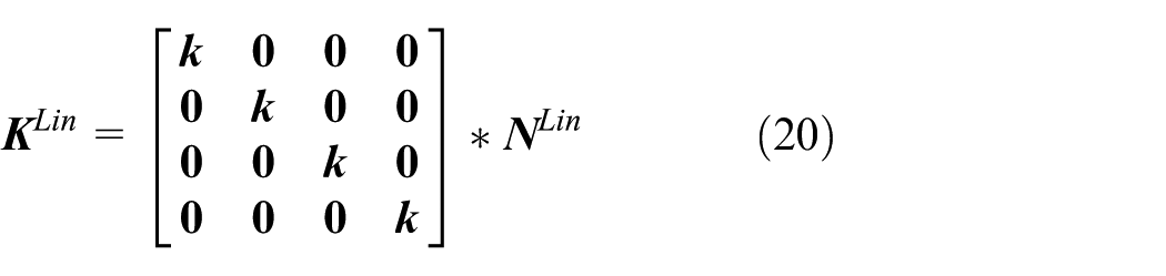
2. Matrix calculation for linear flexible connection
After adding linear flexible connections to these subcomponent models, equation (14) can be rewritten as follows

Without loss of generality, take such a system as an example: four nodes in total, node 1 and node 3 are coupled through linear flexible connection. The calculation of
Define
Therefore
where
If the number of linear flexible connections is greater than one, add the connections one by one

When the stiffness matrix
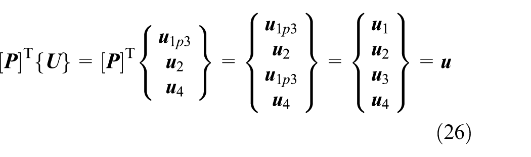
3. Matrix calculation for rigid connection
After adding rigid connections to these subcomponent models, equation (18) can be rewritten as follows

Since the number of effective nodes in the coupling system will be reduced by rigid connections, the generalized displacement in equation (22) is marked by
Define

Therefore


where
If the number of rigid connections is greater than one, add all the connections at a time. Take such a system as an example: five nodes in total, node 1 and node 3 as well as node 2 and node 5 are coupled through rigid connections. The matrix

When the node numbers of all the rigid-connected nodes are known, the matrix

Coupling model of the drum driving system.
Simulation and analyses
Drum load
As illustrated in Figure 6, the dynamic coupling model of the drum driving system is constructed after fixing the

where

Coordinate system of drum load: (a) side view and (b) top view.
Because of the cyclic variation of the number of teeth actually involved in cutting and the nonuniform coal/rock strength, the actual cutting load fluctuates about its mean value. The load fluctuation coefficient, which is defined as the ratio of the peak load to mean load, is set to 1.2 based on the experimental data. 22 The time series of the drum load components are presented in Figure 7.

Time series of drum load: (a) cutting moment component and (b) cutting force component.
Verification of the proposed gear model
In this article, an improved 3D parallel-axis gear model, which has time-varying pressure angle and contact ratio, was proposed to replace Velex’s gear model 21 used in the authors’ previous work. 17 First of all, we should determine (1) whether the outcomes from the proposed model are reasonable and (2) how much is the difference between outcomes from the proposed model and Velex’s gear model, and also whether these differences are explicable.
Figure 8(a) illustrates the dynamic meshing force of the gear pair Z21–Z22 from the proposed model and Velex’s model. It is obvious that the two curves coincide highly with each other. Figure 8(b) illustrates the dynamic factors of various gear pairs from the two models. The biggest difference appears at the gear pair Z12–Z13, an increase of only 0.87%. This is because the variation of gear center distance is insignificant in our case, and the reasons will be further discussed later.
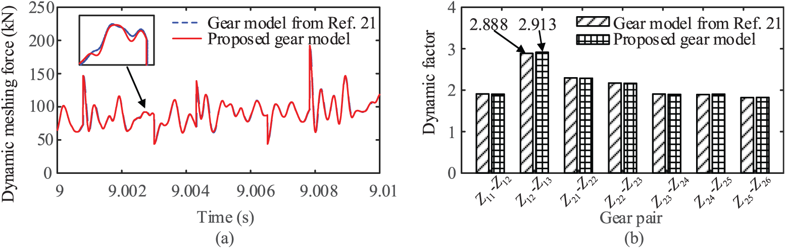
Comparison of dynamic meshing force from the proposed model and Velex’s gear model: (a) dynamic meshing force of the gear pair Z21–Z22 and (b) dynamic factor of various gear pairs.
Figure 9(a) illustrates the equivalent mesh misalignment of the gear pair Z21–Z22 from the proposed model and Velex’s model. The two curves are similar in shape, but different in amplitude. This is because the equivalent mesh misalignment can be enhanced due to the differences of contact ratio and meshing phase between different mesh elements along the tooth width. The proposed model takes this effect into consideration, while Velex’s gear model does not. Figure 9(b) illustrates the peak mesh misalignment of various gear pairs from the two models. It is obvious that the increase of peak mesh misalignment for the second-stage gears is larger than that in the first stage (gear pair Z11–Z12 and gear pair Z12–Z13). Particularly, the peak mesh misalignment of the gear pair Z23–Z24 increases from 17.7 to 26.6 μm (an increase by 50.3%). This is because the tooth width of the first stage is 90 mm, while it is 140 mm for the second stage.

Comparison of equivalent mesh misalignment from the proposed model and Velex’s gear model: (a) equivalent mesh misalignment of the gear pair Z21–Z22 and (b) peak equivalent mesh misalignment of various gear pairs.
The above results illustrate that the proposed 3D parallel-axis gear model is credible, and it is should be used when equivalent mesh misalignment is concerned, especially for wide-faced gear.
Deformation of ranging arm housing
As illustrated in Figure 10, a comparative analysis was conducted between two loading scenarios, that is, M, where only the cutting moment was applied, and M + F, where both the cutting moment and the cutting force were applied. Figure 11(a) illustrates the y-direction deformation of node 1 on the ranging arm housing (the node numbers are presented in Figure 5) under the two loading scenarios. It can be observed that the dynamic displacement of node 1 significantly increases after the three-directional cutting force is applied on the drum. Figure 11(b) presents the root mean square (RMS) values of the deformations of various bearing bores of the ranging arm housing from the motor end to the drum end. In particular, this value increases 386.5 times after the cutting force is applied, implying that the three-directional cutting force is the primary external factor leading to the large deformation of the ranging arm housing. It is also observed that the ranging arm housing deformation displays an increasing trend from the motor end to the drum end, which is indicative of the features of a cantilever.

Two loading scenarios: (a) M loading scenario and (b) M + F loading scenario.

Comparison of ranging arm housing deformation under two loading scenarios: (a) Y-direction deformation of bearing bore BP1 on ranging arm housing and (b) RMS deformation of various bearing bores on ranging arm housing.
Effects of housing deformation on the transmission system
The gears, bearings, and elastic shafts are the components of the drum driving system that are likely to malfunction. This section describes a systematic analysis of the effects of a large housing deformation on the dynamic characteristics of these components.
Effects of large deformation of ranging arm housing on gears
As mentioned previously, the parallel-axis gear model in this study considers the influences of the gear center distance variations on the pressure angle and contact ratio. Figure 12 illustrates the center trajectories of the gear pair Z21–Z22 under two loading scenarios, that is, M indicates that only the cutting moment is applied, while M + F represents both the cutting moment and the cutting force are applied. After applying the 3D cutting force, the gear centers moved to the negative direction of the x-axis, the positive direction of the y-axis (Figure 12(a)), and the negative direction of the z-axis (Figure 12(b)), among which the displacement in the x-direction is the smallest. It can also be noticed that gear
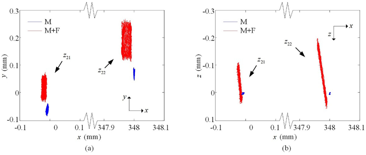
Trajectories of the gear pair Z21–Z22 under two loading scenarios: (a) trajectories in the x–y plane and (b) trajectories in the z–x plane.
Figure 13(a) illustrates the dynamic center distance of the gear pair Z21–Z22 under the two loading scenarios. The amplitudes of the curves
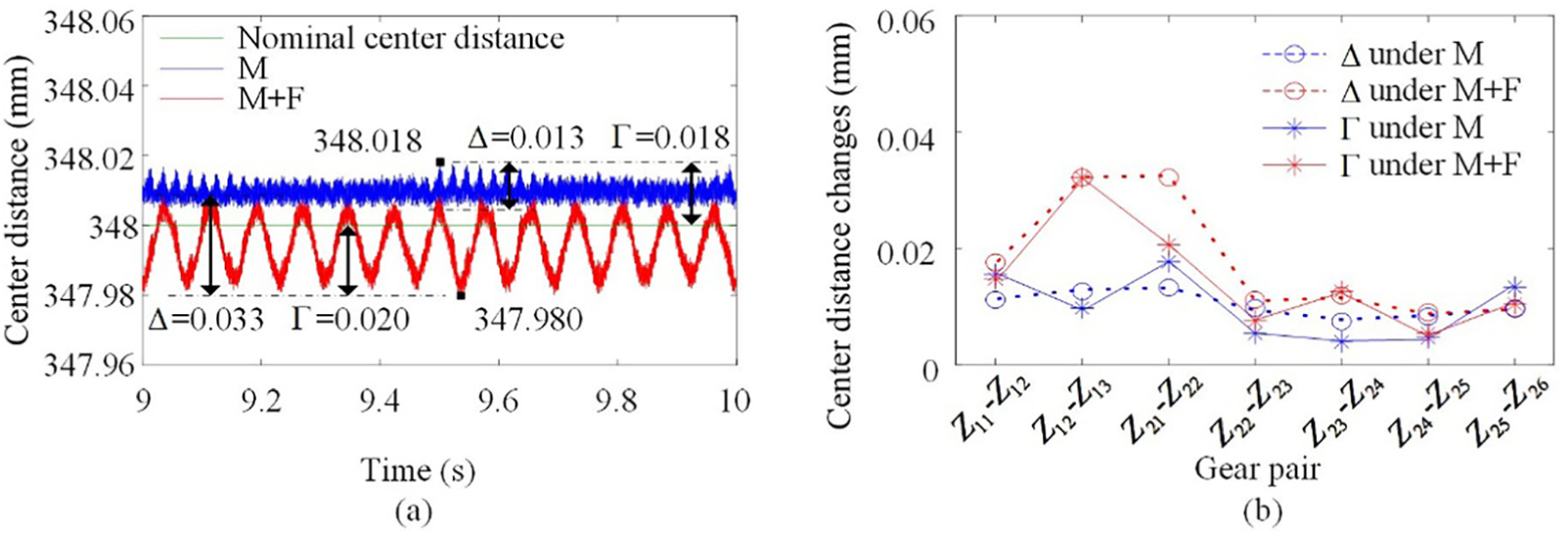
Dynamic center distance of gear pairs under two loading scenarios: (a) dynamic center distance of the gear pair Z21–Z22 and (b) comparison of center distance between various gear pairs.
Figure 14(a) illustrates the dynamic contact ratio of the gear pair Z21–Z22 (in the middle of tooth width) under two loading scenarios, the maximum deviation of which is

(a) Dynamic contact ratio and (b) dynamic meshing force of the gear pair Z21–Z22 under two loading scenarios.
It is valuable to investigate load distribution over the gear face width. Mesh misalignment is closely related to the load distribution along the face width of gears. Figure 15(a) illustrates the mesh misalignment of the gear pair Z21–Z22 under the M and M + F loading scenarios. The peak mesh misalignment, which is 18.7 μm under the M loading scenario, increases to 26.6 μm under the M + F loading scenario (an increase of 42%). Figure 15(b) illustrates the peak mesh misalignments of various gear pairs under the two loading scenarios. It is observed that the large deformation of the ranging arm housing results in a substantial increase in the mesh misalignment of the transmission system. Figure 16 illustrates the spectra of mesh misalignment of the gear pair Z21–Z22 under the two loading scenarios, wherein a significant discrepancy occurs only at 17 Hz. From Figure 11(a), it can be observed that 17 Hz corresponds to the large deformation of the ranging arm housing. This implies that the increase in the mesh misalignment of the gear pairs is caused by the large deformation of the ranging arm housing. Figure 17 illustrates the load distributions of the gear pair Z21–Z22 along the face width under the M and M + F loading scenarios, respectively, over a duration of two meshing periods. It is obvious that the large deformation of the ranging arm housing leads to more serious uneven load, and a larger maximum load density is found. Therefore, it is necessary to adopt a larger face load factor or conduct a lead modification when designing the gears of the transmission system.

Mesh misalignment of gear pairs under two loading scenarios: (a) mesh misalignment of the gear pair Z21–Z22 and (b) comparison of peak mesh misalignment between various gear pairs.

Mesh misalignment spectra of the gear pair Z21–Z22 under two loading scenarios: (a) M loading scenario and (b) M + F loading scenario.
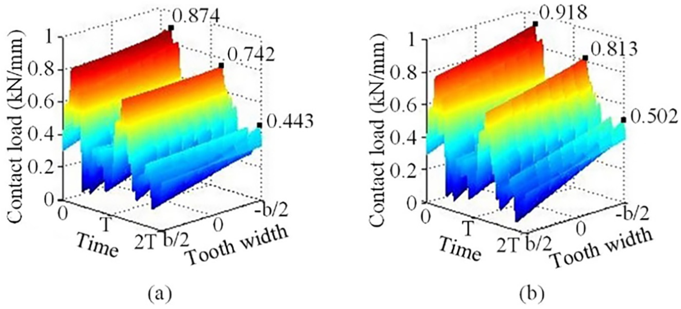
Load distribution of the gear pair Z21–Z22 under two loading scenarios: (a) M loading scenario and (b) M + F loading scenario.
Effects of large deformation of ranging arm housing on bearings
Bearing is a key component of the transmission system of the cutter. The failure of a bearing can result in the failure of the entire transmission system. Figure 18 illustrates the dynamic load of bearing
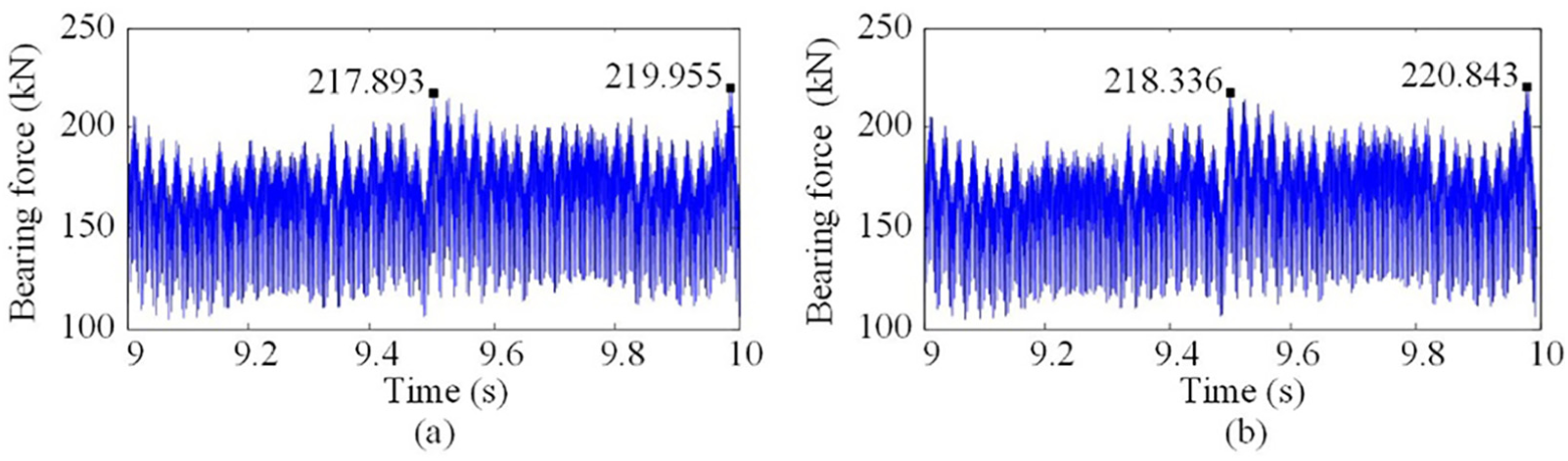
Dynamic loads of bearing B6 under two loading scenarios: (a) M loading scenario and (b) M + F loading scenario.
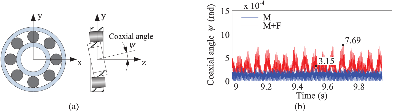
Coaxial degree values of inner and outer races of bearing B6 under two loading scenarios: (a) bearing coordinate and (b) comparison of coaxial angle.
Effects of large deformation of ranging arm housing on elastic shaft
In order to reduce the impact on the transmission system and ensure overload protection, a thin and long elastic shaft is set inside the hollow shaft of the cutting motor, as illustrated in Figure 2. Designing a significantly large safety margin for this elastic shaft will prevent it from breaking when the drum experiences an excessive impact, rendering it incapable of protecting the transmission system. On the other hand, a significantly low design strength for this elastic shaft will result in frequent breaks, affecting the production efficiency. In addition, in order to meet the important trend of unmanned operation in the future mining systems, the torsional vibration of the elastic shaft is used as the feedback signal to reflect the drum load. 9 However, since the housing deformation is neglected, the accuracy of this approach still needs to be validated. The comparative analysis results illustrated in Figure 20 indicate that a large deformation of the ranging arm housing has no significant impact on the torsional deformation of the elastic shaft. This is because the elastic shaft mainly transfers the torque load. As the dynamic meshing forces are almost the same under the two loading scenarios (see Figure 14(b)), the torque load on the elastic shaft has no obvious change. Therefore, it is not necessary to take the housing deformation into consideration in the design of the elastic shaft.

Elastic torsional deformation under two loading scenarios: (a) M loading scenario and (b) M + F loading scenario.
Conclusion
In order to accurately calculate the dynamic meshing force of gears suffering housing’s large deformation, a new 3D parallel-axis gear model was constructed considering the time-varying pressure angle and contact ratio. Then, a standard coupling method was adopted to construct the coupling dynamic model for the complete drum driving system, which simultaneously considers the flexibility of the ranging arm housing, bending and torsional deflection of the gear shaft, nonlinear meshing force of the gear pairs, bearing stiffness, load characteristics of the drum, and mechanical properties of the motor. Simulations under two loading scenarios, that is, M (applying only the cutting moment) and M + F (applying both cutting moment and cutting force), allowed the following conclusions to be reached:
Compared with Velex’s gear model, 21 the equivalent mesh misalignment is larger for the proposed 3D parallel-axis gear model with time-varying pressure angle and contact ratio. The dynamic meshing forces from the two gear models are almost the same, since gear center distance variations are insignificant in our case. Thus, the proposed model is better to be applied when equivalent mesh misalignment is concerned, especially for wide-faced gear.
The three-directional cutting force is the major external factor contributing to a large deformation of the ranging arm housing, which displays an increasing trend from the motor end to the drum end, demonstrating the features of a cantilever. This deformation of the ranging arm housing results in unbalanced loading on both the gears and bearings, which accelerates their damage process; however, it has a negligible impact on the dynamic meshing forces of gears, dynamic loads of bearings, and torsional deformation of the elastic shaft.
Considering the effects of a large deformation of the ranging arm housing on the key components of the transmission system obtained in this study, three guidelines can be recommended for the design of a drum driving system. First, it is necessary to adopt a larger face load factor or conduct a lead modification of gears. Second, it is necessary to select bearings such that the allowed coaxial degree of their inner and outer races satisfies the design requirement. Third, it is not necessary to take housing deformation into consideration in the design of an elastic shaft.
Footnotes
Acknowledgements
The authors would like to acknowledge the support and contribution from the State Key Laboratory of Mechanical Transmissions, Chongqing University, China.
Handling Editor: James Baldwin
Declaration of conflicting interests
The author(s) declared no potential conflicts of interest with respect to the research, authorship, and/or publication of this article.
Funding
The author(s) disclosed receipt of the following financial support for the research, authorship, and/or publication of this article: This research was funded by the National Major Basic Research Program of China (973 Program, Grant No. 2014CB046304).