
Abstract
The meshing process includes high-speed impact between the teeth. The vibration and noise in the gear transmission become prominent owing to the backlash between gears. Currently, the concentrated mass model is primarily used to analyse the vibration and noise mechanism of gear transmission, and it is difficult to effectively explain high-speed gear collision. In this study, an improved impact vibration model was applied to the meshing state of a high-speed gear. The gear transmission was simplified as a collision vibration system with absolute and traversable boundaries, and the piecewise-smooth dynamics model of the gear system is established. A mapping dynamic analysis method was then used to describe the impact and meshing boundary of gears. The impact-meshing situation of the gear system was observed, and the vibration response of the system under different speeds and loads was analysed using numerical simulation. The results revealed that the main source of the gear vibration was the meshing frequency of a gear pair. The resonance generated by the modulation of the rotation and meshing is the main reason for the long-term impact-meshing phenomenon of the gear transmission system. The results of this study are of great significance as they reveal the vibration characteristics of a high-speed gear transmission system.
Keywords
Introduction
Gears are important basic mechanical components widely used in aviation, aerospace, ships, automobiles, wind power and other fields. They are indispensable components in the equipment manufacturing industry, which directly determine the service performance and reliability of the major equipment.1,2 Historically, the gear meshing vibration problem has been considered in a fixed domain and studied using conventional continuous dynamic systems. The obtained results have often been suitable for approximating the dynamic behaviour of the low-speed gearboxes. When high-speed rotation occurs, the vibration and noise in the gear transmission are considerable. Typically, a gear with a pitch linear speed ≥35 m/s or speed >4500 r/min is called a high-speed gear. 3 Unfortunately, the mechanism of the vibration and noise in the high-speed gear transmission cannot be explained using conventional methods. The impact-meshing phenomenon occurring during the meshing process of the gear system has considerable implications for the system. For instance, it may rupture the formed lubricating oil film and simultaneously affect the gear teeth, thus aggravating the friction and wear of the teeth. To represent the mechanism of the vibration and noise in a gear meshing process, Luo and Connor4–7 analysed this problem for the first time by applying the discontinuous dynamical system theory in a dynamic domain. Extensive research on gear transmission has been conducted, but the research on gear meshing and collision in the dynamic domain has been limited.
Hartog and Mikina 8 used undamped piecewise linear systems in fixed domains to analyse the gear mesh dynamics. Ozguven and Houser 9 employed a piecewise linear model and an impact model to describe and analyse the meshing mechanics. Azar and Crossley 10 established a digital simulation model of a light-load gear torsion system comprising a transmission unit, a spur gear pair and flexible shaft connection loads. Further, the changes in the parameters such as the shaft speed, backlash and load were analysed. The results show that the simulation model considerably reflects the torsional characteristics of the output shaft. Xu et al. 11 established an accurate piecewise non-linear dynamic model for the gear transmission by considering the rotary inertia, backlash and friction in the control applications under difficult working conditions. Experiments were conducted for the gear transmission system of a heavy-duty manipulator in start-stop and continuous-rotation conditions. Xiangfeng et al. 12 constructed different Poincaré sections based on the non-linear dynamic model of a single-degree-of-freedom spur gear system with backlash. The dynamic characteristics of the system under different excitation frequencies and torques were simulated using a continuation algorithm and fourth-order Runge–Kutta method with a variable step size. Zhang et al. 13 established the Poincaré map of the single-impact-period nth motions of a linear impact vibration system with a fixed phase plane as the Poincaré section. By analysing the map, the conditions and bifurcation equations for the system to generate the edge-rubbing bifurcation were obtained.
Gear transmission system is a typical non-smooth power system. Research has been conducted on several complex phenomena and problems that uniquely impact non-smooth systems, and on developing their various periodic motions, stabilities and boundary impact bifurcation phenomena (such as edge friction, jumping, sticking, switching and corners). Wang et al.14,15 employed a perturbation method and differential inclusion theory to analyse the sliding dynamics of the separation boundaries. Additionally, the periodic response of a gear pair system was illustrated, and Floquet’s theory was presented to confirm the stability and bifurcation of the periodic response. Cao 16 analysed a class of two-degrees-of-freedom piecewise linear systems and used the zero-time discontinuous mapping method to deduce the local paradigm mapping and jump matrix of the system. He analysed the periodic solution of the system using the flout theory and numerical simulation stability and discovered the cycle-doubling path to chaos. Huang et al. 17 established a non-linear dynamic model for a multi-clearance and high-contact-ratio gear transmission system using a lumped mass method while simultaneously considering the time-varying mesh stiffness, static transmission error, gear backlash and bearing radial clearance. Using bifurcation diagrams, the largest Lyapunov exponent charts, time-domain waveforms, fast Fourier transform (FFT) spectra, Poincaré maps, phase diagrams, the influence of the excitation frequency, gear backlash, mesh damping ratio, error fluctuation and bearing radial clearance on the non-linear dynamic characteristics of the system were investigated. The results revealed that with changes in the analysis parameters, the system exhibited different types of non-linear behaviours and dynamic evolution mechanisms, including period-one, multi-periodic, quasi-periodic, chaotic motions and jump-discontinuity phenomena. In all these cases,18–23 a loss in the continuity or smoothness results in special bifurcations, thereby giving rise to interesting dynamics with more complex features than those of smooth systems.
Hence, in this study, the implicit mapping dynamics method was used to simplify the high-speed gear power system into a collision vibration system with absolute and traversable boundaries, thereby resulting in the establishment of the piecewise-smooth system dynamics model of the gear system with backlash. The process of the impact-meshing cycle was observed using numerical simulation, and the main causes of the long-term disengagement of the gear system were studied using the frequency domain analysis method. The influences of the constant load and load fluctuation components on the impact-meshing vibration characteristics of the gear system were further analysed. Analysing the vibration characteristics of the gear model is crucial for the fatigue failure design and verification of the gear transmission systems with a frequent start and stop. It can also provide a reference for gear wear monitoring and prediction theory based on vibration.
Dynamics model of gear system with backlash
To establish a mathematical model for the entire gear torsion system, including the drive gear, and load, it is necessary to establish an accurate representation, including the inertia effect of the gear and tooth contact, stiffness and tooth profile errors. The piecewise linear solutions were developed using the coefficient of restitution to account for energy loss owing to repetitive impacts. A gear backlash results in a strong non-linearity of the gear drive system. Owing to the occurrence of a gear backlash, we can convert the gear system into a piecewise-smooth system with three motion domains. For simplicity, we assume that the flow of the gear transmission system is sufficiently smooth over the entire state space, except over a hypersurface defined by a scalar function. To clearly highlight the impact of the collision process on the system response, assuming that the collision stiffness of the gear is sufficiently large.
Establishment of mathematical model
A typical four-inertia unit comprises a drive, gear pair and load connected by flexible shafts. When the gear teeth are in contact, the bodies oscillate as a four-inertia system with a mean rotation, as shown in Figure 1. In either case, owing to the relative velocity between the gears, the impact occurs on the forward sides of the gear teeth when contact occurs.

Gear torsional system.
A mathematical model of the geared torsional system is shown in Figure 2, wherein the gear pair is represented by an impact pair. To simplify the model, the torques were represented by horizontal forces, and the angular rotations relative to the mean rotation were represented as horizontal displacements. The mesh sliding friction was ignored, and only the torsional vibration of the gear transmission system was considered.

Model of a geared torsional system using an impact pair.
In this model, xi (i = 1, 2, 3, 4) represents the torsional angular displacement of the gear teeth, input shaft and output shaft. The moments of inertia of the gear teeth, input shaft and output shaft are denoted as mi (i = 1, 2, 3, 4). The backlash of the gear is 2b. The constants k3 and k4 represent the torsional stiffnesses of the input and output shafts, respectively. The equivalent viscous damping coefficients of the input shaft, output shaft and gear teeth are c3, c4 and c, respectively. F1 and F2 represent the load constant, while F3 and F4 represent the load fluctuation components. The function k (t) is the time-varying meshing stiffnesses of the gears. The law of the fluctuation of the speed of the active shaft is expanded into a Fourier series, and the magnitude of the excitation amplitude is an important factor affecting the flapping performance of the system.
Owing to the existence of a backlash, many interesting phenomena can be observed in the gear transmission system. Three motion domains were considered to explain the gear teeth movement based on the backlash. The vibrator can vibrate when both vibrators (m1 and m2) are not in contact. This state is defined as j = 2. To identify the regions of the right- and left-side impact motions, j = 1 and 3, respectively. According to the geometric conditions, the motion between both gears can be classified into three cases as expressed as follows.

Based on the gear meshing state, the equation of motion for this rotating system can be obtained using Newton’s laws as expressed below.

Here, ‘•’ and ‘··’ are the first and the second derivatives, respectively, with respect to time t. The relative penetration depth

The relative penetration velocity

This represents the torque transmitted by the gear teeth, which has a non-zero value only when the gear teeth are in contact. The time-varying meshing stiffness k(t) is expressed as

Here, k0 is the mean mesh stiffness and kw the variation amplitude of mesh stiffness. For the convenience of analysis, the differential equation (equation (2)) must be dimensionless. Introducing the nominal dimension
The dimensionless gear backlash is

The relative penetration velocities

The dimensionless non-linear displacement functions for the backlash are expressed as

The dimensionless time-varying meshing stiffnesses are expressed as

Further,

where
Boundary and analytic conditions
Because the discontinuous boundary in the absolute coordinate system changes with time, the analytical conditions for the motion transformation in a multi-constrained four-degrees-of-freedom impact vibration system cannot easily be obtained. For simplicity, a relative coordinate system was introduced. The relative displacement, velocity and acceleration of block 1 as regards block 2 are defined as
In a relative coordinate system, the relative motion regions of the object blocks m1 and m2 are expressed as

When both gear teeth enter the meshing domain from the free-motion domain, an energy transition occurs, that is, the impact loses energy. When the gear teeth are separated, the energy does not change, but the meshing force disappears. For an intuitive analysis, we further classified the boundary into impact and meshing boundaries. The relative impact boundary is expressed as follows.

The corresponding relative boundary is expressed as

where the subscript ‘21’ denotes the boundary between Domains 2 and 1 and subscript ‘23’ the boundary between Domains 2 and 3. Based on the properties of the sets, the global set

where

Motion boundary and motion domain.
The possible motion and boundary of the gear is shown in Figure 4.

Possible motions and boundaries of the oscillators.
In the relative coordinate system, the following vectors are introduced for the relative motions of m1 and m2:
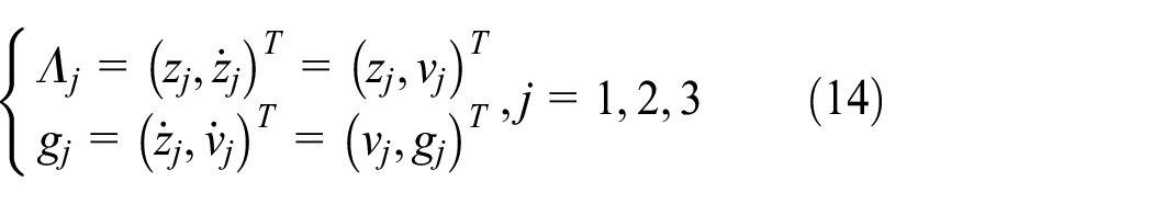
where
For the motion in meshing domains 1 and 3, the relative forces per unit mass of m1 and m2 are expressed as follows:

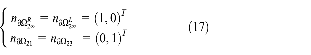
The normal vector of the relative boundary is expressed as

where
From equations (10), (11) and (15), the normal vector of the discontinuous boundary of the system is obtained as follows:
Combined with the theory of flow switchability in discontinuous dynamical systems in Luo and O’connor, 6 a G-function is used to analyse the singularity of the discontinuous dynamical system boundaries. In a relative coordinate system, the zero- and first-order G-functions on the discontinuous boundaries can be simplified as follows:

where
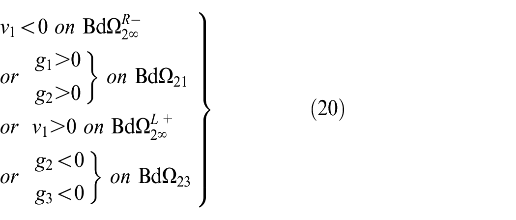
The onset conditions for the impacting chatter in Domain 2 are
Conditions under which tooth meshing in domain 2 are

The condition of tooth meshing vanishing is
Mapping structure
Because the discontinuous boundary in an absolute coordinate system changes with time, the analytical conditions for the motion transformation cannot easily be obtained. Because the impact time is extremely short (usually a few thousandths or tens of thousands of seconds), the restitution coefficient e of an impact is adopted to account for the energy loss owing to the impact.
By defining impact planes according to boundaries,

The meshing switching planes for sticks are defined as

To characterise the complex dynamics in the meshing process of the gear teeth, we introduced impact mapping. When the gear teeth collide, it increases the speed, and the impact transmission law is used to describe the motion continuity of the gear transmission system. In this study, the motion process of the gear was classified into impact and meshing phases, and the restitution coefficient, e, was used to describe the energy loss during the gear impact.
The velocity of any object block after impact can be expressed as
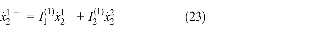
Where ‘−’ represents before the impact, ‘+’ after the impact and i = 1, 2 denote Vibrators 1 and 2, respectively.

According to the gear motion state, the gear tooth meshing process can be sectioned into multistage chattering and meshing. The mapping structure was sectioned into free and meshing mappings. The free mapping represents the motion state when the main and driven gear teeth are not in contact.
In the relative frame, the mappings are also expressed as

P1 and P4 refer to the meshing map of the movement in the meshing domain (

Schematic of the decomposition of the mapping structure.
To simplify the equation, impact maps are implicit in the mapping structure.

The subscript

Results and discussion
The numerical simulation results of the impact and meshing motion of the gear system are presented below to elucidate the motion mechanism of the gear system.
To portray the deep mechanism of the disengagement phenomenon during the gear rotation and meshing process, the dynamic behaviour of the active oscillator was considered the primary observation object, and the impact recovery coefficient e = 0.56 was used to solve the dynamic equation of the inertial system mapping.25 The primary parameters of a typical gear transmission system are presented in Table 1.
List of specific parameters of the gear inertial system.

In the following, the effects of the gear transmission system speed, load fluctuation and meshing frequency on the system response will be solved and analysed, focusing on the mechanism of the gear system collision and meshing.
Numerical simulation of impact and meshing
For the first time, we refined the gear meshing process into impact and meshing. The impact and meshing phenomena of the gears during the starting process were the most typical, capable of elucidating the kinematic mechanisms of the gear impact and meshing. The system analysis diagrams are presented when both the input and output torques are F1 = F3 = 400 N·m. As shown in Figure 6(a), when the rotational speed of the input shaft is 1000 r/min, the gear teeth enter a long-term stable meshing state after multiple impact-meshing cycles under the action of the driving force and load during the start-up process. As shown in Figure 6(b), the gear teeth have three disengagement phenomena, and each disengagement produces multiple impacts. During the process of gear teeth from impact to meshing, the driving gear teeth experienced seven impacts with a very short period before entering the first meshing. The system enters a stable meshing state after a period of time. This corresponds with the working state of the actual gear system.

Operation analysis diagram when the input shaft rotates at 1000 r/min: (a) initial impact and meshing displacement diagrams and (b) drawing of the partial enlargement.
When the active wheel gives the driven wheel a speed, the driven wheel accelerates instantaneously and it is separated from the active wheel at this time, and it is difficult to continue to maintain the fit, thus forming an impact-meshing cycle process.
Figure 7 indicates that the active gear teeth may enter a stable meshing state after multiple collision impacts during the initial meshing process, or they may be in the collision-mesh-re-collision-re-meshing cycle process for a long time.

Vibration response of oscillator 1 at different input speeds: (a) Initial shock and meshing displacement plot at 17,550 r/min and (b) Initial shock and meshing displacement plot at 19,000 r/min.
Dynamic response of the system at different speeds
To investigate the response of the gear system under a stable operation, we define the gear system as a steady state after 10,000 iterations, and obtain the phase diagram and spectrogram of the system.
As shown in Figure 8, when n = 1000 r/min, the gear system moves in one cycle after stable operation. When n = 17,550 r/min, the number of disengagement increases, and the gear teeth move in multiple cycles under stable operation. When n = 19,000 r/min, the gear teeth cannot enter the stable meshing state, and the system enters the chaotic motion state.

Phase and Poincar
To portray the cause of the long-term disengagement, the FFT plot of the gear system at different speeds is solved, as shown in Figure 9. The FFT diagram of the system is obtained by considering the position of the gear teeth at the centre of the backlash as the initial position and the gear system as a stable state after 10,000 iterations.

Spectrogram of the gear system at different speeds: (a) n = 1000 r/min, (b) n = 17,550 r/min and (c) n = 19,000 r/min.
As shown in Figure 9, when n = 1000 r/min, the p–1 periodic solution is dominated by the fundamental vibration with a similar frequency to the meshing frequency of the gear teeth, accompanied by higher harmonics. When n = 17,550 r/min, which does not include shock, the second harmonics and their integral multiorder harmonics appear in the p–n periodic solution of the system, while the fundamental frequency vibration amplitude is still the maximum. When n = 19,000 r/min, there is also a peak in the fundamental frequency component of the chaotic solution with shock; however, the low-frequency component is remarkably abundant. The impact of the gear teeth caused generating complex instability factors in the system and rendered the dynamic behaviour of the flow on the transition boundary relatively more complex and diverse. The disengagement behaviour produced a rough and uneven peak signal in the frequency domain, as shown in Figure 9(c). The rotation and meshing frequencies of the shaft are the main frequency components of the vibration signal of a gear pair in the gear transmission system.
To study the influence of the shaft speed in the high-speed gear transmission system on the gear impact-meshing phenomenon, we drew a waterfall diagram of the gear system.
The waterfall diagram presented in Figure 10 shows that a large number of modulation frequencies occur when the rotational speed lies between 25,000 r/min and 35,000 r/min. The modulation frequency disappears when the speed rises above 35,000 r/min. We observed a noticeable impact-meshing cycle phenomenon of the gear teeth in the resonant frequency band of the gear system. A large number of modulation frequencies are observed because the gear system cannot enter a stable meshing state in this speed range, resulting in a long-term collision-meshing cycle. The resonance caused by the joint action of the rotational frequency and meshing frequency is the primary cause of the long-term impact meshing of the gear transmission system. Concurrently, a distinct frequency band containing the gear meshing frequency is observed, and it can be concluded that the meshing frequency of the gear system is the primary cause of the vibration.
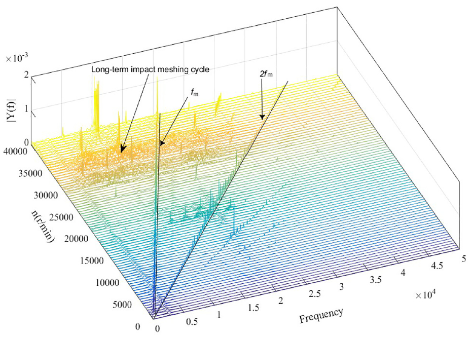
Waterfall diagram of a gear system controlled by the input speed.
Influence of driving load variation on impact-meshing characteristics of gear system
The external excitation of the gear system is an important factor affecting the stability of the gear system. In this study, numerical simulation is used to analyse the shock response of the gear system under different load parameters. Here, the input shaft speed is n = 7200 r/min, load fluctuation amplitude F3 = F4 = 4 N·m and the constant component of load F2 = 400 N·m. The relative displacements of the gear teeth in the starting process under a stable load and different initial driving torques are shown in Figure 11.

Impact and meshing of the gear teeth under different driving torques.
As shown in Figure 11, the relative penetration depth of the teeth can be observed to be the largest in the initial meshing state, which gradually decreased until stable meshing. With the increase in the initial drive torque, the time required for the gear to enter the stable meshing state is shorter. With the increase in the constant component F1 of the driving load, the relative meshing depth between the gear teeth increased, but the meshing impact time of the gear system is reduced correspondingly. However, the number of shock-meshing is not necessarily related to the increase in the constant load. When starting, the driving force was slightly larger than the load, which is beneficial in terms facilitating the rapid entry of the gears into stable meshing.
Select the input shaft speed n = 7200 r/min, F4 = 4 N·m and F1 = F2 = 400 N·m. The relative displacements of the gear teeth in the starting process under stable load and different amplitudes of driving torque fluctuation are shown in Figure 12.

Impact and meshing of the gear teeth under different driving torque fluctuation amplitudes.
The driving load fluctuation component F3 has a minor influence on the impact-meshing characteristics of the system, while the driving load fluctuation component F3 mainly affects the periodic response characteristics of the gear system under the stable running state.
Conclusion
The conventional solution method in the fixed domain cannot portray the operating mechanism of the high-speed impact and meshing of the gear systems. This study presents the novel subdivision of the meshing behaviour of gears into the impact and meshing states based on the corresponding behaviour. The collision vibration model of the multi-DOF gear system is established based on the gear inertia system, considering the torsion stiffness of the shaft and the clearance of the tooth side, and the digital simulation of a certain gear system is performed. The results demonstrate that the method can effectively describe the collision and meshing phenomenon of the gear system, and can quickly estimate the speed interval when the gear system is out of meshing over an extended period. The findings of this study are as follows.
The piecewise-smoothing dynamics model of a gear system was established based on the discontinuous dynamics, and the collision and meshing processes of the gear were simulated using a numerical method. In the initial meshing process, the gear teeth entered the meshing state after several impacts within a considerably short period. Here, the gear teeth may enter a stable meshing state after multiple impacts, or they may be in the collision-meshing cycle for a long time.
The long-term impact meshing of gears can be identified based on the modulation frequency generated by the rotation of the shaft and meshing of the gears. This provides a theoretical reference for the health state management of gear systems. The change in the driving load considerably affects the depth of the gear meshing collision, while the fluctuation component of the load does not significantly affect the impact meshing characteristics of the system.
This model represents a novel approach for describing the collision and meshing behaviour of gear systems. There are various new problems to be solved in this gear system model, which must be accumulated and improved during the practical application. For example, more accurate time-varying meshing stiffness can be adopted, and the dynamic characteristics of the gear system can be analysed with different backlash and damping coefficients. This study provides theoretical guidance for the design and analysis of the high-speed gear transmission system.
Footnotes
Handling Editor: Chenhui Liang
Declaration of conflicting interests
The author(s) declared no potential conflicts of interest with respect to the research, authorship, and/or publication of this article.
Funding
The author(s) disclosed receipt of the following financial support for the research, authorship, and/or publication of this article: This work was supported partially by the Heilongjiang Province Major Scientific and Technological Achievements Transformation Project [Grant No. CG21B010], Heilongjiang key research and development plan [Grant No. GA21D004] and the Fundamental Research Funds for the Central Unicersities [Grant No. FRFCU5710052921].