
Abstract
Dual-driving systems have been widely adopted in advanced manufacturing machine. Synchronization of the dual-servo systems is crucial for tracking reference trajectories. This article proposes a novel cross-coupled fuzzy logic sliding mode control for the synchronous control of dual-driving feed system. The dynamic model of dual-driving system has been established and the individual proportional–proportional–integral controller is built based on the dynamic model. To increase the synchronous performance, a cross-coupled sliding mode controller is provided based on dual-driving system model. In addition, a continuous saturation function is adopted to reduce chattering. Lyapunov stability criterion is used to analyze the stability of the cross-coupled sliding mode control. Moreover, a fuzzy logic saturation gain control approach is proposed to overcome the low robustness and poor dynamic synchronous performance in the normal cross-coupled control scheme. The adaptive saturation function is designed to eliminate synchronous deviation caused by the process of two axes following each other. Finally, an industrial application of dual-driving system is utilized to prove the effectiveness of the proposed scheme. The proposed cross-coupled fuzzy logic sliding mode control scheme has been effectively demonstrated to improve synchronous performance and tracking accuracy.
Introduction
With the increasing demand for higher precision and greater productivity, modern machine tools have been required to have multiaxis synchronous or coordinated motion, such as gantry machine, computer numerical control (CNC) press brake, turret punching, and robotic arms. 1 The dual-driving feed system with high-precision synchronous performance has been widely adopted to facilitate the automated process. A typical application of dual-driving system can be seen in precise gantry machine. As shown in Figure 1, two permanent magnet synchronous motors (PMSMs) and screws are utilized instead of the traditional single motor and screw structure in the same direction. The dual-driving structure can improve stiffness and reduce the inertia of feed system. Moreover, the drive by center of gravity (DCG) technology based on dual-driving system can significantly decrease the vibration and extend bandwidth of control system.

Configuration of dual-driving gantry machine.
Another application of dual-driving system is double-load press brake, shown in Figure 2. Once the workpiece has been clamped and detected, the double-load motors are simultaneously moved to press the parts. Compared with single-load bending, double-load bending generates a smoother shape of workpiece and increases the capability and productivity.

Diagram of double-load press brake: (a) photograph of double-load press brake and (b) schematic of double-load press brake.
As the dual-driving system tracks complex trajectories, the motion accuracy depends not only on the system capability and tracking accuracy in each independent axis but also on the synchronous control. 2 However, the synchronous performance inevitably suffers from the different servo characteristics, unbalanced forces, and mechanical coupling. Especially in high-speed and high-precision machining, when the dynamic characters such as the sudden change in velocity and mismatched disturbance are imposed to the system, the synchronous accuracy is hard to be guaranteed.
The most previous control approach of dual-driving system is mechanical rigid coupling. Both axes are joint feed based on the mechanical line-shaft or connection rods. 3 However, the mechanical rigid synchronization heavily depends on the manufacturing and assembling accuracy of structure. The synchronous performance will be decreased by mechanical transmission error and wear.
The electrical control approach offers various merits in high accuracy and low cost for maintenance. A coupled control approach of dual-driving system is called master–slave control. For its simple structure, master–slave control has been widely adopted in practical industry. The position or velocity signal of the master motor is used as reference input command to the slave, which generates an unavoidable delay between the dual-driving systems. And the load disturbance imposed on the slave axis cannot be fed back to the master, which leads to a poor synchronous performance in the load disturbance situation. The electronic virtual main shaft control has developed to eliminate the unbalance problem based on the master–slave theory. 4
Another synchronous control approach called cross-coupled control was first proposed by Koren, and it was designed to eliminate contour error in two-freedom feed system. After years of improvement, applications of this strategy become more widely. 5 Some researchers proposed the cross-coupled synchronous control algorithm to control biaxial gantry structure of surface mount machine, and the optimized cross-coupled control is studied in the high-speed and high-precision dual-driving system.6–9 Compared with the parallel uncoupled control and master–slave control, cross-coupled control strategy has a better synchronization and tracking performance. It is shown that the cross-coupled controller, when properly designed, can be used to compensate the synchronous error of dual axes. However, cross-coupled control is achieved by a synchronous controller. The controller will calculate the position error of dual axes in closed loop, which fundamentally makes the dual axes follow and move against each other in high frequency which is defined by the controller and sampling rate. The following process of dual-driving axes inevitably generates an oscillation of the dual-driving system. 2
In order to improve the dynamic performance of cross-coupled control in dual-driving system, some researchers apply the advanced algorithm, that is, adaptive or robust control in synchronous control.10,11 Since in dual-driving system, the synchronous error is caused by nonlinear factors such as servo characteristics diversity and mechanical coupling which cannot be modeled, sliding mode control (SMC) is particularly suited for dual-driving nonlinear system for its good performance in nonlinear system. A sliding mode controller with vibration compensation is proposed and verified to have better robustness than traditional proportional–integral–derivative (PID) position control.12,13 However, chattering involving high-frequency control switching may lead to excitation of unmodeled high-frequency system dynamics. Especially in dual-driving system under cross-coupled control, the chattering phenomenon in conjunction with mechanical coupling will exacerbate the synchronous error in the condition of reversing and sudden changing of acceleration. To overcome this drawback, the integral SMC which adopts tan h function to replace signum function is proposed to decrease the switching process. Various SMC studies incorporated with adaptive or intelligent control are presented to achieve both tracking and synchronous accuracy. In some studies, the adaptive fuzzy SMC is proposed to achieve a better performance. 14 Fuzzy logic control (FLC) has been known to be an effective tool for parameter-varying plant. 15 The adaptive and robust control algorithm with disturbance observer using digital signal processor (DSP) or control board has been applied in tracking control of motors.16,17 The control law with disturbance estimation guarantees a good performance in tracking for induction motor in terms of load disturbances and speed changing. For the apparent advantages of both SMC and FLC in nonlinear system having been noticed, considerable researches have been motivated in combining these two control approaches.18,19 The adaptive logic SMC has been presented to improve the tracking accuracy in many researches. 20 The control strategy which combines FLC and SMC serves to reduce the limitations of the sliding mode, while still maintaining the guarantees of global uniform stability.
However, widening the bandwidth and improving disturbance rejection of single axis are not enough to achieve precise synchronization in a dual-driving feed control system. There are two main problems that restrict the development of dual-driving feed system. First, since the synchronization precision is affected by the system characteristics of dual axes, the diversities of servo parameters, transmission features, and disturbances can lead to the synchronous errors. This implies that precise synchronization control is required, which aims not only to achieve high tracking accuracy but also to eliminate the synchronous error between the dual axes. Second, the mechanical coupling can give rise to the desynchronization in conjunction with the cross-coupled control which existed in the industry application. Especially in the sudden change of acceleration, the mismatch between unbalance driving force and dynamic characteristics of dual axes will cause a fluctuation of synchronous error. In dual-driving system, the fluctuation of unbalance torque caused by mechanical structure would reduce the synchronization performance. Hence, the strategy of the synchronization controller should introduce robust coupling between two drives and penalize synchronous errors that generated due to disturbances, as well as parameter diversities. Moreover, a smooth switching process should be suggested to reduce the fluctuation of synchronous error in the process of dual-driving axes following each other.
In this article, a novel cross-coupled fuzzy logic sliding mode control (CCFLSMC) is proposed for synchronous control with consideration of practical application in the dual-driving system. The feed positions of dual axes can be measured by double linear encoders. The contributions of this work can be listed as follows:
This work focuses on the practical application of dual-driving feed system. The dynamics model composed of double feed systems is derived, and the theoretical analysis of dual-driving synchronous control is described in detail. The single axis is controlled in the drive level with proportional–proportional–integral (P-PI) controller which is tuned by linear quadratic regulator (LQR) method.
In order to reduce the synchronous errors, a novel cross-coupled SMC controller is introduced based on drive model. In this controller, a cross-coupled SMC with disturbance observer is applied to eliminate the synchronous errors caused by mechanical-coupled disturbances between dual axes. The disturbance observer can effectively estimate the uncertainty disturbances to enhance system robustness. However, the original SMC requires high-frequency switching around the sliding surface resulting in a chattering phenomenon, and the dual axes working against each other will inevitably generate an oscillation. Hence, the switching function is replaced by a continuous smooth saturation function which aims to eliminate the chattering phenomenon. Moreover, the saturation gain is determined by FLC which generates a soft signal to eliminate synchronous deviation caused by dual axes following each other in cross-coupled control. Then, the Lyapunov stability analysis of proposed synchronous control scheme is provided to guarantee closed-loop tracking stability.
Finally, an industrial application of dual-driving system is utilized, and electromechanical co-simulation and dual-driving experiment were conducted to compare the performance of the proposed CCFLSMC with other two synchronous control schemes. The co-simulation and experiment results show the effectiveness of the proposed CCFLSMC scheme.
The rest of this article is organized as follows: section “Dual-driving servo drive model” presents the dual-driving dynamics model; section “Proposed CCFLSMC controller” introduced the proposed controller; the simulation and experimental results are presented in section “Dual-driving co-simulation and experiment”; and, finally, conclusions are drawn in section “Conclusion.”
Dual-driving servo drive model
The dual-driving feed system is composed of two AC200-v PMSMs in this article, namely, on the same feed direction, there are two motors, incorporating with dual guidance rails and detecting instruments.
The dual-driving system considered here is controlled in the drive level. In order to test the presented synchronous control scheme, considering the driving system as rigid body dynamics, the ratio of transmission system is also designed to be as 1, and the influence of the armature transfer function is simplified as 1.
The open-loop transfer function of the dual-driving servo system between the displacement y and equivalent torque command

The state vector parameters are given as follows

where

The drive model of dual-driving servo system is shown in Figure 3. Considering dual-driving system, the synchronous control can be separated into two components at the same time: the first one is to eliminate the tracking error according to a given position signal, and the second one is to preserve the synchronous position with the other motor. 18 The simplified architecture of dual-driving control system is depicted in Figure 4.

Drive model of dual-driving servo system.

Configuration of dual-driving control system.
As to the single axis, the position tracking error can be described as follows

where
The synchronous error between dual axes is

Proposed CCFLSMC controller
Sliding mode synchronous controller design
Considering the dual-driving feed system, the feed accuracy and stability depend not only on the tracking accuracy in individual axes but also on the synchronous performance of dual axes. Cross-coupled control is used for eliminating the synchronous error in this section; however, the cross-coupled controller make the dual axes follow and track each other in high frequency, which inevitably generate an oscillation of the dual-driving system. In order to eliminate the following process, a synchronous cross-coupled SMC control scheme is proposed based on the drive dynamics in this section.
The sliding surface is designed as follows

where c is the sliding mode gain coefficient,
The Lyapunov function which is used to obtain a stable control law is designed for the SMC

If equations (2) and (10) are substituted into equation (11), the derivative of Lyapunov function can be obtained

The SMC contains two fundamental processes, the reaching motion and sliding motion. The Lyapunov stability criterion could only guarantee that system can reach switching surface in finite time. However, in order to improve the dynamic quality of reaching motion, the exponential reaching law is designed as follows

where

The external uncertainty disturbances

The derivative of the Lyapunov function should be negative definite, and the control law can be derived as follows
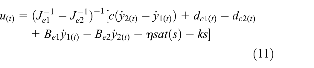
where
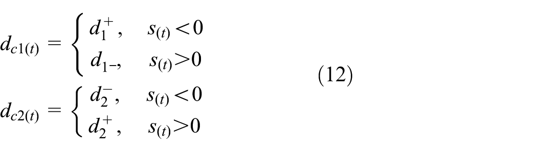
Then, the disturbances can be designed as follows

where
The Lyapunov equation can be derived as follows

The overall diagram of proposed dual-driving CCFLSMC is shown in Figure 5.

Proposed cross-coupled SMC synchronization control architecture.
Saturation gain FLC
In order to achieve high-quality sliding mode motion, most approaches of SMC are designed to increase the saturation gain
Figure 6 shows the diagram of fuzzy logic sliding mode control (FLSMC) controller. As can be seen, the inputs of the proposed controller are synchronous error and its derivative which can also be applied to the sliding surface. Table 1 shows the membership functions (MFs) of these inputs. The output of this fuzzy logic block is saturation gain

Fuzzy logic control structure.
Rule base of FLC.

FLC: fuzzy logic control; NL: negative large; NS: negative small; ZE: zero; PS: positive small; PL: positive large; B: big; M: middle; S: small.
Fuzzy inference mechanism and fuzzy rule are depicted in Table 1. The objective of
If
When the SMC system state run away from sliding surface
If
When the SMC system state reaches the sliding surface
The curved shape of MFs will affect the resolution of the fuzzy subset and the sensitivity of the control. In this study, for the FLSMC controller, triangle-type MF is used for the determination of saturation gain for its high sensitivity and simple structure. The input and output MFs are assumed to be triangle type, and the input MFs are designed as follows (Figures 7 and 8)

where

Input membership functions.

Output membership functions.
The output of defuzzification can be defined as follows 24

where
The objective of FLSMC is to control the saturation gain
The intervals of input and output MFs are designed based on practical dual-driving feeding test. The normal cross-coupled SMC is adopted to estimate a relatively large bound of the synchronous error. The velocities and accelerations of dual axes are given at various constant velocities from 5 to 500 mm/s and 50 to 5000 mm/s
2
, according to the working space and demands. At the stage of sudden change of acceleration, the synchronous error is about
The MFs of the input variable are decentralized, and the interval coverage area becomes narrower with the language value level getting lower. In this case, the sensitivity of MFs can be improved when the input variables are small. The controlled parameter will be decreased to eliminate chattering phenomenon once
By substituting equation (16) in equation (11), a new FLSMC law can be obtained

It should be noticed that the parameters contained in the control law will directly affect the control performance. The inertia and damping parameters
The Lyapunov function (14) can be reformatted as follows
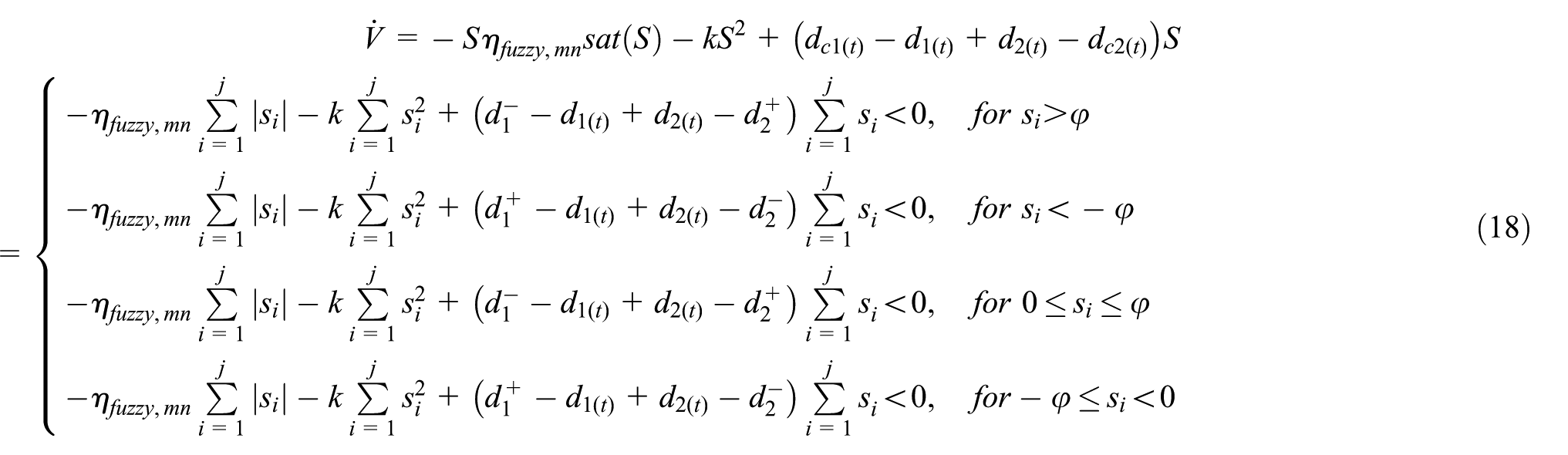
In the above equation, the parameters
Individual P-PI controller design
PID feedback control is widely accepted in servo system control. The individual controller consists of position-control loop and velocity-control loop which should be designed. The current-control loop is inherent in the servo amplifier which just need to be tuned to achieve high accuracy.
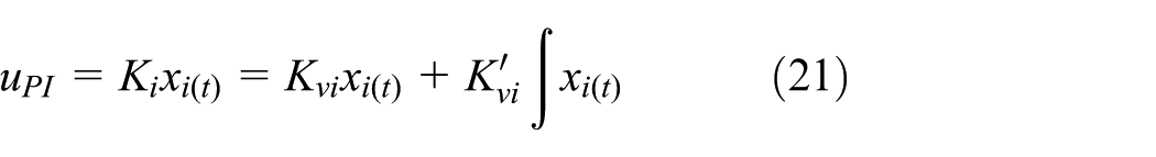
In the position loop, the input command
First, assuming the gain of P controller is 1. The transfer function of velocity PI controller can be expressed as follows

where
The drive model without uncertainty disturbance can be rewritten as follows

where

where P is the symmetric positive definite coefficient matrix which can be obtained by

where
Once the velocity loop is tuned properly, the P controller needs to be added as position loop.
Dual-driving co-simulation and experiment
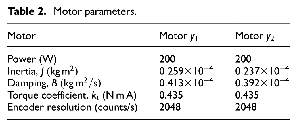
Several control schemes have been developed to achieve synchronization motion in dual-driving system, as mentioned in section “Introduction.” In this section, the proposed FLSMC scheme will be analyzed comparing with other control schemes by simulation. The simulation parameters are listed in Table 2. All parameters are designed in accordance with the practical dual-driving system.
Motor parameters.
In order to elaborate the advantages and disadvantages of cross-coupled control, an electromechanical co-simulation is presented as shown in Figure 9. First, the cross-coupled control has been analyzed with master–slave control, which is widely applied in practical industry. The control diagrams of these two synchronous approaches are shown in Figure 10(a) and (b). Motors

Diagram of dual-driving co-simulation.

Control strategy of dual-driving system: (a) cross-coupled control and (b) master–slave control.
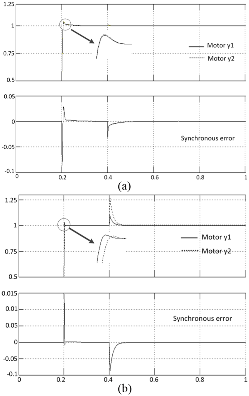
Step response of different control strategies: (a) cross-coupled control and (b) master–slave control.
Then, a comparison simulation of the proposed CCFLSMC, cross-coupled normal sliding mode control (CCNSMC), and cross-coupled proportional–integral–derivative (CCPID) is presented. Figure 12 shows the simulation results on reference trajectory, single-axis tracking errors, and synchronous errors with different control schemes. Motors

Simulation results of CCPID: (a) reference trajectory of feed experiment, (b) tracking error of dual motors, and (c) synchronous errors of dual motors.
The tracking errors of each axis are shown in Figures 12(b), 13(b), and 14(b). The synchronization error of dual-driving system is shown in Figures 12(c), 13(c), and 14(c). Due to the CCFLSMC synchronous controller, the proposed synchronous control scheme has a much less synchronization error than the other two control schemes, especially when sudden change of velocity and reversing occur; the fuzzy logic adjust gain can significantly eliminate the synchronous error. Moreover, the synchronization performance is much better in the steady process from the synchronization error curves. And it is worth noting that the CCPID control has the relatively maximum synchronous error.

Simulation results of CCNSMC: (a) reference trajectory of feed experiment, (b) tracking error of dual motors, and (c) synchronous errors of dual motors.

Simulation results of the proposed CCFLSMC: (a) reference trajectory of feed experiment, (b) tracking error of dual motors, and (c) synchronous errors of dual motors.
Finally, the proposed CCFLSMC synchronous controller is experimentally tested on a dual-driving system. The setup of the overall dual-driving system is shown in Figure 15(a) and (b), which are the mechanical structure and the control system, respectively. Two PMSMs which consist in the dual-driving system are driven separately by identical motor amplifiers. The desired input signal is given by control cards integrated in personal computer (PC), and the entire system is connected by EtherCAT Bus. The hardware architecture is shown in Figure 16.

Dual-driving test system: (a) description of mechanical structure and (b) description of control system.

Overall structure of dual-driving system.
The synchronous control schemes are applied to the dual-driving system using “C” and MATLAB/Simulink languages. The control card is integrated in PC, so that the control algorithm, motion control, and other NC tasks can be executed at different levels of central processing unit (CPU), which provide a much better real-time communication property. The codes of the proposed control scheme generated in MATLAB can be called as modules in controller. After the input command is set, the feedback loop is realized by the encoder sampling and linear encoder feedback and then the actual positions are calculated by the proposed synchronous control algorithm to compensate the tracking and synchronous errors.
In this way, the synchronous controller can be used in the control cards as a function block with inputs and outputs. The parameters and test conditions are designed to be the same as in the simulation. After the input command is set, the feedback loop is realized by the encoder sampling at 10 kHz and then the synchronous errors are calculated by the algorithm. Finally, the dual motors are driven by the current commands disposed in the inherent current loop.
Each amplifier runs in the current-control mode, and the current loop is inherent in the servo amplifier. The current loop facilitates better servo characteristics by producing current proportional to input voltage and then generates the reference input of motor.
The designed individual P-PI controller is tuned to achieve a high tracking accuracy for individual motor as shown in Figures 17 and 18. These figures display the velocity response curves by adjusting the weight in LQR. The weight matrices Q and R determine the state variables with different inputs. The feedback gain matrix K is calculated by MATLAB. Q and R are initialized as

Tuning of P-PI controller in motor

Tuning of P-PI controller in motor

Frequency response of the proposed dual-driving scheme.
To investigate the effectiveness of the proposed CCFLSMC in different test conditions, two cases with different input signals are presented in the experiment:
Case 1: trapezoidal signal whose stroke is
The experimental results of CCPID, CCNSMC, and proposed CCFLSMC at case 1 are shown in Figures 20–23. Figure 20 illustrates the reference trajectory of dual motors due to trapezoidal signal. The tracking errors of y1-axis and y2-axis are shown in Figures 21(a), 22(a), and 23(a). The synchronous error of dual-driving system is shown in Figures 21(b), 22(b), and 23(b).

Reference trajectory of dual axes at case 1.

Experiment results of CCPID at case 1: (a) tracking errors of y1-axis and y2-axis and (b) synchronous error of dual-driving system.

Experiment results of CCNSMC at case 1: (a) tracking errors of y1-axis and y2-axis and (b) synchronous error of dual-driving system.

Experiment results of the proposed CCFLSMC at case 1: (a) tracking errors of y1-axis and y2-axis and (b) synchronous error of dual-driving system.
Case 2: trapezoidal signal whose stroke is
The experimental results of CCPID, CCNSMC, and proposed CCFLSMC at case 2 are shown in Figures 24–27. Figure 24 illustrates the tracking responses of dual motors. The tracking errors of y1-axis and y2-axis are shown in Figures 25(a), 26(a), and 27(a). The synchronization error of dual-driving system is shown in Figures 25(b), 26(b), and 27(b).

Reference trajectory of dual axes at case 2.

Experiment results of CCPID at case 2: (a) tracking errors of y1-axis and y2-axis and (b) synchronous error of dual-driving system.

Experiment results of CCNSMC at case 2: (a) tracking errors of y1-axis and y1-axis and (b) synchronous error of dual-driving system.

Experiment results of the proposed CCFLSMC at case 2: (a) tracking errors of y1-axis and y2-axis and (b) synchronous error of dual-driving system.
As can be seen in Figures 21–23, a quite smaller tracking error and better synchronous performance of the dual-driving system can be obtained at case 1 than at case 2, as seen in Figures 25–27. Once rapidly changing of velocity occurs, the difference between dual axes inevitably induces the synchronous error and heavily decreases the control accuracy.
However, CCNSMC and proposed CCFLSMC have a much less synchronous error than normal CCPID for the advantage of SMC. The proposed CCFLSMC has a favorable tracking response and synchronous performance benefits from FLSMC in handling uncertainty disturbances, as seen in Figures 21(b), 22(b), and 23(b). Although the tracking and synchronous errors increase with a higher frequency in case 2, acceptable tracking and synchronous errors are obtained from the proposed CCFLSMC, as seen in Figures 25(b), 26(b), and 27(b). In fact, CCFLSMC modifies desired trajectories sent to the dual drives and improves the synchronization between the dual axes significantly.
In addition, the peak and average values of the CCPID, CCNSMC, and proposed CCFLSMC for the tracking and synchronous performances of dual-driving test at cases 1 and 2 are shown in Table 3. Compared with CCPID and CCNSMC, the synchronous errors of the proposed CCFLSMC are reduced dramatically, and the undesired dynamics synchronous errors in sudden changing of velocity are also degraded according to the maximum errors. Furthermore, the proposed CCFLSMC generates much less tracking errors than CCPID and CCNSMC. To sum up, the proposed CCFLSMC has good performance with respect to the precise synchronization and tracking as well as offering an acceptable performance to the sudden changing of velocity.
Experimental results of dual-driving test.

CCPID: cross-coupled proportional–integral–derivative; CCNSMC: cross-coupled normal sliding mode control; CCFLSMC: cross-coupled fuzzy logic sliding mode control.
Conclusion
A novel synchronous control scheme of a dual-driving system has been investigated in this article. First, the mathematical model of the dual-driving system has been established based on the simplified dynamics of servo drives. Then, the proposed scheme was designed by combining the P-PI controller in individual axis and cross-coupled SMC in synchronous controller. To eliminate the undesired dynamics caused by switching gain in SMC, a fuzzy logic saturation gain control is presented. Furthermore, the stability of the proposed CCFLSMC is analyzed using Lyapunov stability criterion. Finally, the proposed CCFLSMC is validated in the co-simulation and experiments. When compared to CCPID and CCNSMC, the proposed control scheme has the best synchronous and tracking performance in a dual-driving system. As a result, the proposed CCFLSMC scheme can be effectively used in gantry and dual-driving machines, and it is also possible to be applied in coordinated motion. Although the proposed scheme is based on a dual-driving machine, it involves substantial simplifications of mechanical characteristics. To confirm the results of the proposed synchronous control scheme, a more complete analysis of the vibration modal and dynamic testing is suggested to improve model accuracy and optimize parameters for further studies.
Footnotes
Appendix 1
Handling Editor: Mario L Ferrari
Declaration of conflicting interests
The author(s) declared no potential conflicts of interest with respect to the research, authorship, and/or publication of this article.
Funding
The author(s) disclosed receipt of the following financial support for the research, authorship, and/or publication of this article: The work was supported by The National Natural Science Foundation of China (no. 51675393) and Innovation Fund of Wuhan University of Science and Technology (no. 165204002).