
Abstract
This article presents a numerical study of the stability of a hydraulic excavator during performing lifting operations. A planar dynamic model is developed with six degrees of freedom, which considers the base body elastic connection with the terrain, the front digging manipulator links, and the presence of the freely suspended payload. Differential equations describing the excavator dynamic behavior are obtained by using the Lagrange formalism. Numerical experiments are carried out to study the excavator dynamic stability under different operating conditions during the motion along a vertical straight-line trajectory. It is shown that the arising inertial loads during the movement of the links along the vertical trajectory, combined with the payload swinging and the motion of the base body, decreases the excavator stability. It was found that the excavator stability during following vertical straight-line trajectory decreases considerably in the lower part of the vertical trajectory. If the stability coefficient is close to 1, the payload swinging can cause the separation of a support from the terrain; nevertheless, the excavator stability can be restored. A method for tire stiffness and damping coefficients estimation is presented. The validation of the dynamical model is performed by the use of a small-scale elastically mounted manipulator.
Introduction
Due to the considerable efforts in the industry in the past decades, the hydraulic excavators have transformed from specialized heavy-duty earth-moving machines, whose primary function is the digging, into multifunctional devices. By the use of specialized attachments and working tools, they can perform a wide variety of technical tasks that are specific for other types of machines. This has allowed many operations at the construction and mining sites to be performed by a smaller number of machines and, thus, to increase the economic efficiency.
One of the widespread activities is the use of the hydraulic excavators as cranes. 1 The typically performed operations are lifting, moving, and positioning of freely suspended payloads, such as concrete pipes and beams, industrial equipment, and construction elements. The payload is attached by slings to the lifting points, hooks, lifting eyes, lashing points, or other special attachment that has been provided and approved by the excavator manufacturer.
Despite the undeniable convenience when using an excavator as a crane, the lifting operations performed have some peculiarities, leading to the reduction of the excavator exploitation reliability. Basically, excavators are not designed for lifting operations and the operator is trained to perform earth-moving operations but not to manipulate freely suspended payloads. Even in the case of a very skilled operator, this leads to an undesirable payload swinging and, as a consequence, to the increase of dynamical loads, which negatively influences the excavator exploitation reliability. The reduced ability of the excavators to perform lifting operations increases the risk of accidents with the staff near the excavator, and especially in the vicinity of the freely suspended payload. The statistical reports show a considerable risk of injuries caused by the strike by the bucket or swinging boom. 2 Edwards and Holt 3 have studied the hazards associated with using construction excavators as cranes and have investigated the catastrophic failure of a link. The same authors have studied excavator overturn accidents. 4 According to Lim et al., 5 38% of the excavator accidents in Korea are due to performing lifting operations. Some requirements for the safety of the excavators are presented in the standards.6,7
The literature survey reveals different aspects of the excavator exploitation as a crane. Some documents emphasize on the practical aspects of the problem, 8 while other papers aim at the design and development of a research methodology and simulation models. Lim et al. 5 presented the application of the Zero Moment Point theory to the computation of the excavator stability during performing lifting operations. Yu et al. 9 introduced the Static Compensation Zero Moment Point algorithm that has a more accurate output compared to the general algorithm. Heep et al. 10 proposed a method for payload estimation by the use of a multibody simulation.
Reduced overturning stability is the most critical indication of reduced exploitation reliability as it may even lead to accidental situations. The problem of using excavators as cranes and investigations of their overturning stability during performing lifting operations in the vertical plane of the front manipulator motion has not received enough attention over the years, mainly because such type of work operations are not typical for this type of machines, but are performed in practice. In this aspect, more attention has been given to some other machines that are similar to the excavators. Although ensuring the stability of the mobile machinery is an up-to-date subject and intensive research is carried out to improve it, much of the recent research does not take into account the dynamic nature of the loading due to the payload swinging, elastic supports, and moving links.11,12 Rauch et al. 13 developed a dynamic model of a mobile boom crane and studied the tip-over stability by a simplified semi-dynamic approach to account for the payload swing and inertia forces. Since the dynamic stability is influenced by the foundation–soil interaction, Messioud et al. 14 used complex mathematical models, but Towarek 15 obtained adequate results for the dynamic stability of a boom crane by the use of a two-parameter rheological model for the representation of the soil. Abo-Shanab and Sepehri 16 presented the development of a model that can adequately simulate the dynamic stability of manipulators mounted on moveable platforms. Janosevic et al. 17 investigated the influence of the hydraulic transmission oil temperature on the excavator dynamic stability. The presented mathematical model takes into account the hydraulic cylinders compliance due to the hydraulic fluid compressibility. Another research by Mitrev et al. 18 resulted in a complex multibody model of a classical hydraulic excavator, based on the use of Lagrange multipliers, which allows the study of dynamic behavior during digging operations. The approaches for dynamic modeling and control of different types of cranes were presented in the very detailed and extensive study by Abdel-Rahman et al. 19 Fodor et al. 20 presented a very interesting approach based on an input shaping control technique for oscillation reduction in the vertical plane of a forestry crane in order to improve the overturning stability of the machine.
Along with the widely used free or commercial computer codes for simulation of multibody systems, the dynamic models of a wide range of physical systems are formulated and studied by use of analytical21–23 or numerical techniques. 24 Setting the mathematical model represents the very core of dynamic modeling of such type of systems composed of hydraulic and mechanical subsystems. 25 Recent investigations26,27 show the feasibility of such an approach to study dynamic behavior of excavators, despite the fact that in certain cases, the resulting dynamic equations are quite demanding to resolve. However, the literature review also shows that the available dynamical models of excavators and similar mobile machines cannot be used reliably for all types of performed operations because the models do not include the peculiarities of the hydraulic excavator kinematic structure in performing lifting operations and especially the presence of a freely suspended payload attached to the bucket and elastic support. For this reason, the main aim of this article is to numerically investigate the dynamic behavior and overturning stability of the hydraulic excavator during performing lifting operations. For this purpose, kinematic and dynamic models of the excavator are developed, and numerical experiments are carried out to study dynamic behavior of the system in different operating conditions.
This article is organized as follows: “Introduction” section lists some peculiarities during the performance of lifting operations by hydraulic excavators. Some studies concerning different aspects of the dynamic modeling of the excavators and similar machines are reported. “Kinematic model and trajectory planning” section presents the solution to the inverse kinematics task and describes the trajectory planning. “Dynamic model” section is focused on dynamic modeling of the excavator and the derivation of the system of differential equations. “Overturning stability of the excavator” section points out some peculiarities concerning the excavator overturning stability. The results of the numerical experiments are shown in “Numerical experiments and discussions” section. In “Parameter estimation and validation of the mathematical model” section, a method for determination of the tire characteristics and experimental model validation are presented. The article concludes with a summary in “Conclusion” section.
Kinematic model and trajectory planning
Figure 1 shows a hydraulic excavator performing typical lifting operation—lifting/lowering of the payload R along the vertical straight-line trajectory. The cutting edge, denoted by H, serves as a reference point for the start

Schematic view of an excavator performing lifting operations.
In the first case, the cutting edge H moves along a straight line and the angle of the bucket tilt is kept constant relative to the stick. In this case, the manipulator is considered as a system with two controllable degrees of freedom—the boom and the stick together with the bucket—and one uncontrollable degree of freedom—the free payload swinging.
The motion of the cutting edge along the trajectory leads to the change of the bucket orientation φ with respect to the horizontal line (see Figure 1), resulting in a change of direction of the payload weight force according to the lifting point causing its unfavorable loading. The other drawback due to the bucket rotation is the occurrence of the horizontal movement of the lifting point P which induces a payload swinging and, as a consequence, poor positioning of the payload and increased risk of accidents, especially in confined spaces.
In the second case, during the motion along the vertical trajectory, the bucket hydraulic cylinder is additionally controlled to maintain a constant bucket angle φ. The system has four degrees of freedom, three of which are controlled and one is uncontrolled. The above described motion along a predefined trajectory can be considerably facilitated by the use of the widely used 28 and well-studied excavator automatic digging system.29–31
The current article investigates the second case. The values of the angles
The goal of the trajectory planning is to transport the payload from the initial point

where tf denotes the duration of the motion along the trajectory.
Dynamic model
Figure 2 shows a geometrical layout of the excavator with the consideration of the payload swinging. The excavator mechanical system is modeled as an open kinematic chain undergoing planar motion and consisting of a base body (composed of traveling and swing bodies, represented as a single body), boom, stick, bucket, and payload. The links are interconnected by rotational joints and are subjected to forces generated by the hydraulic actuators and gravity. Each link is characterized by its geometrical and inertia parameters. The base body is connected to the ground by spring-damper elements which represent the elastic and damping properties of the excavator compliant tires, outriggers, or undercarriage. The presented system has six degrees of freedom, and thus, six generalized coordinates are used to define the system geometrical configuration. The base body can move in the vertical direction—generalized coordinate s (heave)—and rotate according to its mass center C1—generalized coordinate θ1 (pitch). The boom, stick, bucket, and payload can rotate according to the connecting joints (points E, F, G, and P)—the corresponding generalized coordinates are θ2, θ3, θ4, and θ5. All angles are measured counterclockwise.

Dynamic model of the hydraulic excavator.
An up-to-date analysis of methods suitable for derivation of the mathematical models of cranes is presented in Abdel-Rahman et al. 19 In order to derive a dynamic model suitable for the study of the lifting operations, in this article, we make the following assumptions: (1) the payload is considered as a point mass; (2) the stiffness of the excavator elements is neglected, and they are considered as rigid bodies; (3) the inertia properties of the hydraulic cylinders and linkages are included into the inertial parameters of the boom, stick, and bucket; (4) the backlashes and the friction forces in the joints are neglected; and (5) the compliance of the hydraulic cylinders is neglected.
The dynamic equations of motion of the excavator during the lifting operations are derived in a systematic way using the Lagrange formalism 33
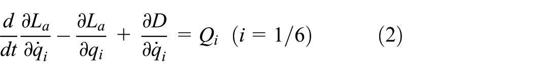
where the Lagrangian La represents the difference between the kinetic T and potential P energies of the system studied, D denotes the dissipation energy of the system, and Qi are the generalized forces associated with the generalized coordinates.
The kinetic and potential energies of the system are positive definite quadratic forms of the, respectively, generalized velocities
Kinetic energy of the system
The total kinetic energy of the system comprises the kinetic energies of the base body T1, boom T2, stick T3, bucket T4, and swinging payload T5. Using the notations in Figure 2 and according to König’s theorem, the total kinetic energy of the mechanical system is obtained as follows
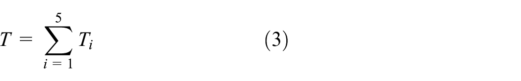
where
As is shown in Figure 2, a local CS {xiyi} is connected to every link of the kinematic chain. The CS {x1y1} is connected to the gravity center C1 of the base body, the CS {x2y2}, {x3y3}, {x4y4}, and {x6y6} are connected to the joints E, F, G, and P, respectively. The transition between the local CS is performed by the use of transformation matrices in the following form

where i and j denote the numbers of the adjacent CSs, α is the angle between the CSs,
Potential and dissipative energies of the system
The potential energy of the system is computed as a sum of the potential energies of the links PG and the deformations of the springs Pk

The potential energy of the spring deformation is easily determined by use of Figure 3, where the dashed line depicts the position of the base body when the springs are undeformed. In this position, the gravity center C1 of the base body coincides with the beginning O of the global CS. The normal line shows the position of the base body when the springs are deformed due to the vertical translation s and rotation θ1.

Scheme for determining spring deformation.
If ΔyB denotes the vertical spring deformation in point B, then

where
Denoting the local coordinates of point B in the base body local CS by

and

then for the spring deformation, one can write

In a similar manner, for the deformation of the spring in point A, we have

Then, the total potential energy of the spring deformation is

The potential energy of a single excavator link is computed as the work required to raise its gravity center according to the x axis of the global CS, that is, it is a function of the system geometrical configuration. The potential energy of the links is the sum of the potential energies of the base body

where
The dissipative energy of the system has the same structure as the potential energy (equation (11)) of the spring deformation, thus
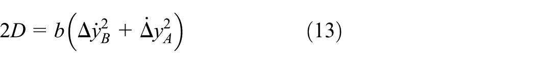
Using the already determined deformations of the spring-damper elements and their first derivatives, it is possible to determine the dynamic forces in the spring-damper elements, attached to the points A and B

One can take into account that during the normal operating conditions, the computed forces must have only negative or zero values, which corresponds to the negative or zero values of the spring-damper element deformations. In case of positive values of the spring-damper element deformations, a separation of the tires from the terrain is observed and the spring-damper elements are not active anymore.
Differential equations of the system
Using the derived equations for the kinetic, potential, and dissipative energies and performing the mathematical operations in equation (2), the nonlinear dynamic equations of motion of the excavator are obtained in the form of

The notations used are as follows: inertia matrix
Due to the already available inverse kinematics solution for the generalized coordinates θ2, θ3, and θ4 and their corresponding velocities and accelerations (see “Kinematic model and trajectory planning” section), the system of differential equations (15) are divided into two sets.
The first set of equations consists of the three equations which describe the motion of the system for coordinates θ1, θ5, and s:

where
The second set consists of the rest of the equations used to compute the necessary driving torques τ2, τ3, and τ4

where
Overturning stability of the excavator
As Alexandrov 34 states, the overturning stability of the mobile machine is defined as its ability to resist the overturn. The excavator performing lifting operations will overturn around the tipping axis (point B, see Figure 2) if the overturning moment is greater than the restoring moment for a sufficient period of time. The excavator overturning stability is estimated by the overturning stability coefficient
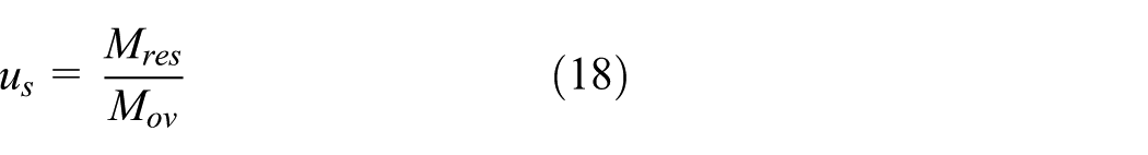
whose value must be equal or greater than 1.15. In equation (18), Mres and Mov denote the sums of the restoring and the overturning moments around the excavator tipping axis, respectively. When us = 1, the balanced condition is reached and the reaction in the left support (point A) becomes equal to 0.
The arising inertial loads during the movement of the links, combined with the payload swinging and motion of the base body due to the elastic mounting and soft ground, can contribute to the decreasing of the excavator overturning stability. That is why during the performance of lifting operations, the dynamic character of Mres and Mov must be considered and the dynamic stability coefficient
Numerical experiments and discussions
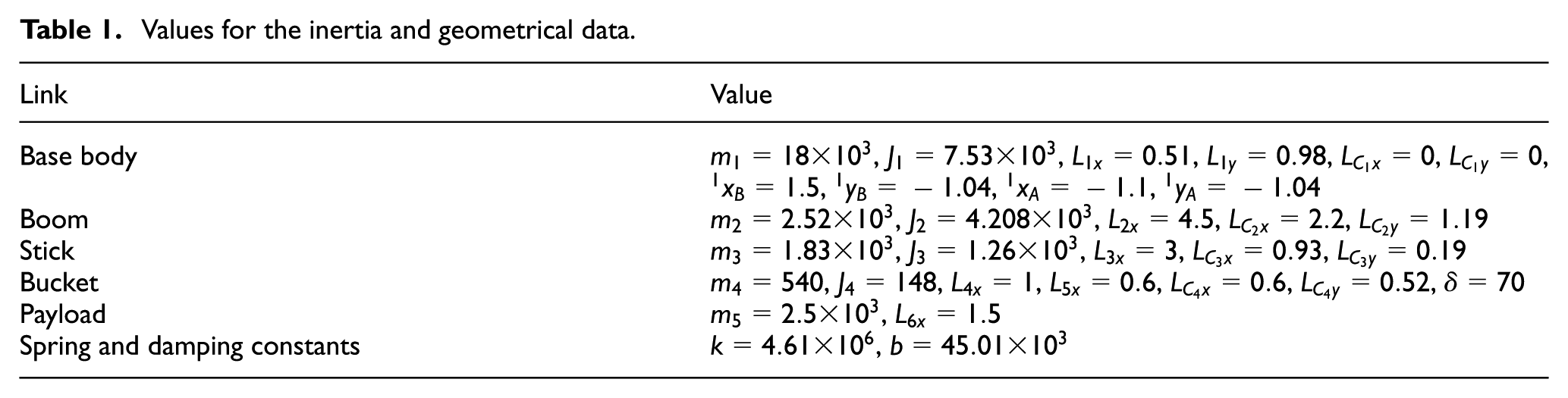
The developed system of differential equations (15) is used in order to perform numerical experiments for different operating conditions and study the excavator static and dynamic stability. The inertia and geometrical data are obtained by CAD modeling of a real-life excavator design. The numerical values used for the inertia, geometrical, stiffness, and damping data of the excavator elements are shown in Table 1, where the measurement units are as follows: for mass (kg), for mass moment of inertia (kg m2), for length (m), for angles (degrees), for spring constant (N/m), and for damping coefficient (Ns/m).
Values for the inertia and geometrical data.
To study the dynamic behavior of the system during the different operating conditions, a few simulations are carried out for the following parameters of the trajectory:
In the first simulation, the initial angle of the payload is set to θ5(0) = 20° (0° from the vertical position), which corresponds to the motion along the vertical trajectory without a payload swinging. In the second simulation, the initial angle of the payload is set to θ5(0) = 10° (10° from the vertical position), which corresponds to the presence of a payload swinging.
To clarify the dynamical behavior of the excavator, frames from the motion animation of the two considered cases are shown in Figure 4. The following notations are used: 1—mechanical structure; 2—trajectory of the gravity center CG of the whole structure; 3, 4, 5, and 6—the trajectories of the gravity centers C2, C3, C4, and R of the boom, stick, bucket, and payload, respectively. It is remarkable that despite the constant distance between the payload R and the right support B during the vertical motion along the trajectory 7, the gravity center CG of the whole system moves toward the right support, but still remains between the two supports. The reasons for that are the variable boom and stick x-positions (curves 3 and 4), also the payload swinging and base body motion, thus reducing the stability reserve. This fact must be taken into account during the excavator exploitation and used to create the mobile machine load charts for the considered case.
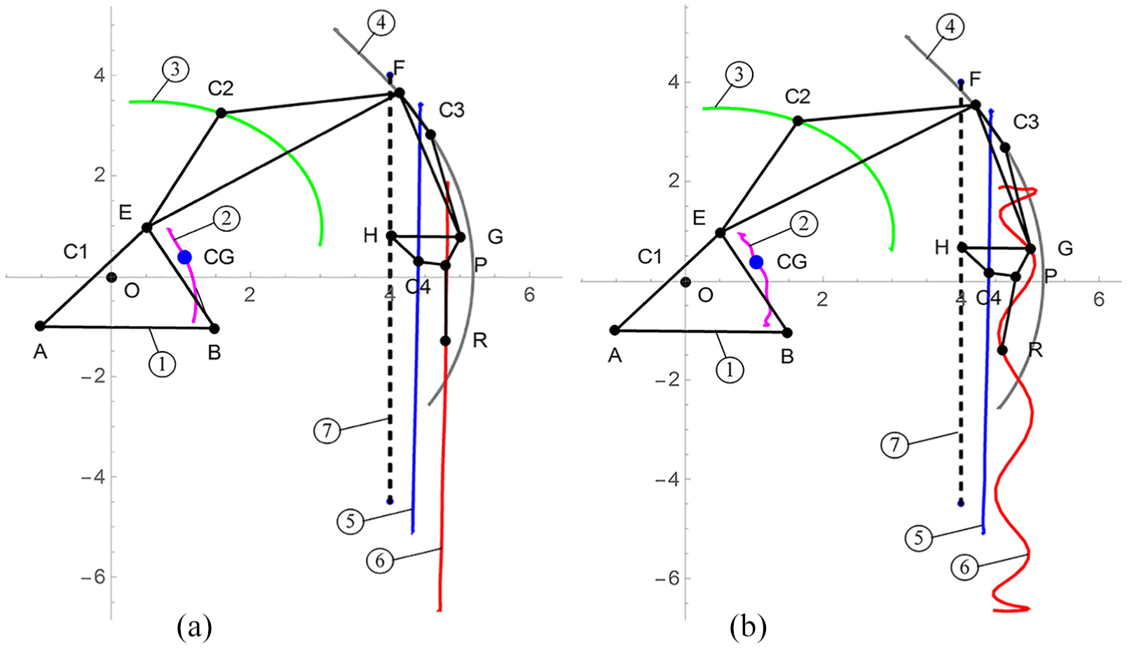
Frames of the motion animation and trajectories of the specific points: (a) in the absence of payload swinging and (b) in the presence of payload swinging.
For the case without a payload swinging, in Figure 5(a), the static coefficient of stability

Static
To study the system dynamic behavior when the stability coefficient is close to 1, additional numerical experiments are conducted. For this purpose, the mass of the payload is chosen to be m5 = 4300 kg and the simulation model is modified to allow the separation of the left support (see Figure 2, point A) from the ground. The total length of the simulation is set to 17 s. The first numerical experiment is performed without a payload swinging. Figure 6(a) shows the time evolution of the deformation of the spring in the left support ΔyA, computed according to equation (10). The shape of the deformation graph is influenced by the vertical motion of the payload combined with the vibrations due to the elastic mounting. The values of the deformation are negative during the simulation interval. Around 7.5 s, the deformation is very close to 0 which means that balance point is reached, but the left support is still in contact with the ground. The time evolution of the dynamic stability coefficient for the considered case is shown in Figure 6(b).

Time evolution of the system characteristics (in the absence of payload swinging): (a) spring deformation and (b) dynamic stability coefficient.
The second experiment is performed in the presence of payload swinging, achieved by setting the initial value of the payload angle equal to 7°, measured from the vertical position. Figure 7(a) clearly shows the separation of the left support from the ground—the maximum value of ΔyA is 0.08 m. After the first separation, one can see three consecutive impacts between the base body and the terrain. Although the left support is separated for a certain period of time, the excavator initial position has been restored. Figure 7(b) shows the graph of the dynamic overturning stability coefficient corresponding to the case studied. Compared to Figure 6(b), the overturning stability coefficient is smaller and at t = 8.5 s, its value is less than 1.

Time evolution of the system characteristics (in the presence of payload swinging): (a) spring deformation and (b) dynamic stability coefficient.
A typical real-world case is the lifting of the payload laying on the ground with loose slings, that is, the load is lifted with a non-zero initial bucket speed. The simulation results for motion with loose slings for 2 s accompanied by the payload swinging are shown in Figure 8. In this case, during the sling tightening due to the vertical motion, a sudden displacement of the system gravity center to the right support (see Figure 2, point B) is occurred, accompanied by the left support separation (see Figure 8(a)) and a sudden overturning stability decrease which is restored later (Figure 8(b)).

Time evolution of the system characteristics (in the presence of payload swinging): (a) spring deformation and (b) dynamic stability coefficient.
Another operating condition causing the change in the excavator dynamic behavior is the sudden change of the payload weight due to the payload spillage or slings and hanging elements failure. In Figure 9, the results of the simulation during the payload raising and sudden change of the payload weight are shown, and in Figure 10, the same during the payload lowering is shown. As one can observe, both cases lead to oscillatory motions of the mechanical system, but without extremal values and support separation.

Time evolution of the system characteristics (in the presence of payload swinging): (a) spring deformation and (b) dynamic stability coefficient.

Time evolution of the system characteristics (in the presence of payload swinging): (a) spring deformation and (b) dynamic stability coefficient.
Parameter estimation and validation of the mathematical model
Tire stiffness and damping characteristics estimation
The accuracy of the simulation results strongly depends on the accuracy of the dynamic model parameter values. While the inertia and geometrical parameters are determined relatively easy by proper measurements, calculations, and CAD modeling, the stiffness and damping properties have to be determined by an experimental research. Although the excavator tires are complex structures with nonlinear characteristics that depend on a number of factors, 35 under certain load conditions, their stiffness and damping properties in the vertical direction can be adequately modeled as a linear spring connected in parallel combined with a viscous damper. A number of methods are used to estimate the numerical values of the stiffness and damping coefficients, among which is the well-known Free-Vibration Logarithm Decay Method. Typical usage of this method includes the application of an impulse loading to a single tire and the use of the measured free vibrations signal for estimation of the stiffness and damping coefficients values. The main advantage of this method is that it allows estimating the stiffness and damping coefficients of the tire together with the contacting surface. Due to difficulties to test the single tire in this study, a new method is presented here to carry out the study of the tire elastic and damping characteristics.
The excavator base body jointly with the fixed in a certain configuration digging manipulator without payload (see Figure 2) is represented as a single rigid body with two degrees of freedom, mounted on linear springs and viscous dampers in parallel. Two generalized coordinates represent the oscillatory motion of the excavator—vertical motion s of the gravity center C and in-plane rotation θ according to the same point (see Figure 11(a)).

(a) Dynamic model of the excavator, represented as a single rigid body, and (b) experimental and fitted curves of the gravity center vertical motion acceleration.
An impulse loading is applied to the oscillatory structure by the excavator boom lowering at maximal velocity followed by a sudden stopping caused by the corresponding hydraulic valve closing. The appeared free decaying oscillations of the structure are measured by a two-axis accelerometer mounted on the chassis in the point M, shown in Figure 11(a). Under the assumption of small oscillations, the following equation is used to determine the generalized acceleration

whereby ax and ay are denoted the xM and yM accelerations, captured by the accelerometer.
Based on the theory of the free decaying oscillations, the motion of the body along the vertical translation coordinate is presented in the following form

where ωdk is the kth damped natural angular frequency,

and to calculate the characteristic polynomial fe(λ) coefficients

The system of differential equations, describing the free decaying oscillations of the presented two degrees of freedom system, is

where
Comparing the experimentally determined coefficients
Inserting notations


For m = 22,890 kg, J = 154,320 kg m2, LA = 2.5 m, and LB=0.5 m, the calculated values are k=4610 kN/m and b = 45,098 Ns/m.
Validation of the mathematical model
The mathematical model is validated by the comparison between the simulation and the experimentally obtained data. 36 For this purpose, a small-scale elastically mounted manipulator, depicted in Figure 12, with known geometrical and inertial parameters and having the same kinematic structure as the considered excavator is used. The manipulator consists of an arm and forearm and allows free suspension of the load to the forearm distal end. It consists of the following main elements: a rotating column 1, an arm 2, a forearm 3, and a hydraulic power unit 4. The structure is equipped with sensors for measuring six different quantities as follows: (1) the pressures at the cap end and the rod end of the arm 5 and forearm 6 driving cylinders 5 and (2) the displacement of the arm and the forearm driving cylinders 7 and 8. For the displacement measurement, two Linear Variable Inductance Transducers are used, attached to the hydraulic cylinders, while for the pressure measurement, four pressure sensors to measure absolute pressure are utilized. Analog outputs from the sensors are measured, converted, and transmitted to the computer measurement system 9 by an analog-to-digital converter.

View of the small-scale manipulator and sensor placement.
The lifting process starts with a fixed in a certain forearm, payload laying on the ground and loose slings. The process corresponds to the following sequence of motions: (1) arm raising—from initial angle θ1 = –12° to angle θ1 = 20.5°; (2) dwell phase in the upper position; and (3) arm lowering to the initial position.
The experimental data for the measured quantities are shown in Figure 13(a): (1) the pressure at the cap end of the arm, (2) the pressure at the rod end of the arm, (3) the pressure at the cap end of the forearm, (4) the pressure at the rod end of the forearm, (5) linear displacement of the arm cylinder, and (6) the linear displacement of the forearm cylinder. As can be expected, the payload swinging inserts an additional low-frequency variation in the pressures—see Figure 13(a), curves 1–4. The following phases with time length ti can clearly be distinguished in the displacement of the arm cylinder (see Figure 13(a), line 5): 1—arm raising without payload (loose slings), 2—arm raising with payload (tight slings), 3—fixed arm (dwell phase), and 4—arm lowering.

(a) The experimental and (b) the comparison between the experimental and the simulation data.
The measured and filtered linear displacement signal of the arm hydraulic cylinder (Figure 13(a), line 5) is used to perform a simulation by the use of the theoretical mathematical model (equation (15)) with the corresponding known numerical values of the small-scale manipulator parameters. In Figure 13(b), the obtained by the simulation torques of the arm and forearm are used to determine the driving hydraulic cylinders forces (arm—line 1, forearm—line 3) shown together with the experimental forces (arm—line 2, forearm—line 4), determined by the use of the measured hydraulic cylinders pressures, presented in Figure 13(a), lines 1–4. Although some differences are observed during the duty cycle, the good correlation between the experimental data and simulation results allows us to conclude that the adopted mathematical model may confidently be used to simulate the dynamic problems presented.
Conclusion
In this article, we have studied the dynamic stability of a hydraulic excavator during performing lifting operations. The developed dynamic model with six degrees of freedom considers the base body elastic connection with the terrain, the front digging manipulator links, and the presence of the freely suspended payload swinging. A system of non-linear differential equations describing the dynamic behavior is obtained by using the Lagrange formalism. Numerical experiments are carried out to study the excavator dynamic overturning stability during the motion along a vertical straight-line vertical trajectory under various operating conditions. Finally, the mechanical system model has been validated by a small-scale experimental model.
The revealed basic insights allow a deeper understanding of the dynamic behavior of the excavator during performing lifting operations along the vertical trajectory. It is shown that the arising inertial loads due to the movement of the links, combined with the payload swinging, motion of the system gravity center, and the motion of the base body, decrease the excavator overturning stability. It was found that the excavator overturning stability while following a vertical straight-line trajectory decreases during the motion from the higher to the lower part of the trajectory. If the stability coefficient is close to 1, the payload swinging can cause the separation of a support from the terrain; nevertheless, it was found that the excavator overturning stability can be restored. The low-frequency vibration, induced in the hydraulic cylinders by the payload swinging and the base body elastic mounting, should be taken into account during the hydraulic system design and its improvement. The proposed calculation method for estimation of the elastic and damping characteristics of the supports is based on the experimental data fitting and can be used reliably.
The decrease of the overturning stability coefficient due to the payload swinging and moving gravity center of the system is very important from the exploitation point of view and this knowledge should be used for the following:
Correction of the existing and creation of new mobile machine load diagrams in order to keep the overturning stability reserve demanded by the standards;
Education of the excavator operators to account for the specific aspects of the excavator dynamical behavior during performing lifting operations.
Footnotes
Handling Editor: James Baldwin
Declaration of conflicting interests
The author(s) declared no potential conflicts of interest with respect to the research, authorship, and/or publication of this article.
Funding
The author(s) disclosed receipt of the following financial support for the research, authorship, and/or publication of this article: We acknowledge support by the German Research Foundation and the Open Access Publication Fund of TU Berlin.